EP0497111B1 - Armature - Google Patents
Armature Download PDFInfo
- Publication number
- EP0497111B1 EP0497111B1 EP92100331A EP92100331A EP0497111B1 EP 0497111 B1 EP0497111 B1 EP 0497111B1 EP 92100331 A EP92100331 A EP 92100331A EP 92100331 A EP92100331 A EP 92100331A EP 0497111 B1 EP0497111 B1 EP 0497111B1
- Authority
- EP
- European Patent Office
- Prior art keywords
- fitting according
- fitting
- bearing bush
- plastic
- fastening means
- Prior art date
- Legal status (The legal status is an assumption and is not a legal conclusion. Google has not performed a legal analysis and makes no representation as to the accuracy of the status listed.)
- Expired - Lifetime
Links
- 239000000463 material Substances 0.000 claims abstract description 17
- 239000002131 composite material Substances 0.000 claims abstract description 4
- 239000004033 plastic Substances 0.000 claims description 8
- 229920003023 plastic Polymers 0.000 claims description 8
- 239000004952 Polyamide Substances 0.000 claims description 5
- 229920002647 polyamide Polymers 0.000 claims description 5
- 238000002347 injection Methods 0.000 claims description 3
- 239000007924 injection Substances 0.000 claims description 3
- 238000001746 injection moulding Methods 0.000 claims description 3
- 230000001681 protective effect Effects 0.000 claims 3
- 229920002430 Fibre-reinforced plastic Polymers 0.000 claims 2
- 239000011151 fibre-reinforced plastic Substances 0.000 claims 2
- 239000000919 ceramic Substances 0.000 claims 1
- 239000011521 glass Substances 0.000 claims 1
- 239000003365 glass fiber Substances 0.000 description 4
- 238000010276 construction Methods 0.000 description 3
- 239000002184 metal Substances 0.000 description 3
- 238000003860 storage Methods 0.000 description 3
- 238000004519 manufacturing process Methods 0.000 description 2
- 238000000034 method Methods 0.000 description 2
- 241000207836 Olea <angiosperm> Species 0.000 description 1
- 239000004743 Polypropylene Substances 0.000 description 1
- 239000004793 Polystyrene Substances 0.000 description 1
- 238000004140 cleaning Methods 0.000 description 1
- 238000001816 cooling Methods 0.000 description 1
- 238000005336 cracking Methods 0.000 description 1
- 230000003670 easy-to-clean Effects 0.000 description 1
- 238000001125 extrusion Methods 0.000 description 1
- 239000002241 glass-ceramic Substances 0.000 description 1
- 230000003287 optical effect Effects 0.000 description 1
- 230000000149 penetrating effect Effects 0.000 description 1
- 230000035515 penetration Effects 0.000 description 1
- -1 polypropylene Polymers 0.000 description 1
- 229920001155 polypropylene Polymers 0.000 description 1
- 229920002223 polystyrene Polymers 0.000 description 1
- 239000002990 reinforced plastic Substances 0.000 description 1
- 238000010079 rubber tapping Methods 0.000 description 1
- 230000007704 transition Effects 0.000 description 1
Images

Classifications
-
- E—FIXED CONSTRUCTIONS
- E05—LOCKS; KEYS; WINDOW OR DOOR FITTINGS; SAFES
- E05B—LOCKS; ACCESSORIES THEREFOR; HANDCUFFS
- E05B15/00—Other details of locks; Parts for engagement by bolts of fastening devices
- E05B15/02—Striking-plates; Keepers; Bolt staples; Escutcheons
Definitions
- the invention relates to a fitting part for doors or windows for receiving an operating element with an upper and a lower part made of different materials.
- fitting parts are attached as door shields, lock plates, window olives or the like, directly to a door or a window (for example document DE-U-7 028 712). They are used to hold an operating element, such as a door handle, a latch, a rocker arm, and possibly a locking cylinder. With regard to suitability for use in particular, it is important that such fitting parts are designed to be stable. At the same time, the surfaces should be smooth, possibly also glossy, in order to ensure easy cleaning and to enable visually appealing designs.
- the invention has for its object to provide a fitting part of the type mentioned above, which enables a compact design with high stability and ensures a secure fit of the upper part.
- the object is achieved by a fitting part according to claim 1.
- the training as a composite component enables a very compact, stable construction, inevitably ensuring a tight fit of the upper part on the lower part.
- the lower part consists of a glass fiber and / or ceramic reinforced plastic.
- the lower part consists of glass fiber reinforced polyamide, which has good storage properties with little wear.
- a glass fiber content of 30% is preferably provided.
- the lower part is designed as a rib construction.
- This design also has the advantage that when using a plastic for the production of the lower part there is a very uniform shrinking process when cooling and the lower part remains true to size and dimension.
- a permanent connection of the upper part and the lower part results from the fact that the lower part is extrusion-coated by the upper part.
- the upper part forms the visible sides of the fitting part.
- the lower part has a bearing bush for the operating element. Since the lower part is made of a material of good stability, for example reinforced polyamide, it can be assumed that this design of the bearing bush enables very wear-free storage. In particular, it is provided that the bearing bush of the lower part engages in the upper part, possibly also reaching through it. Because the control panel generally comes into contact with the fitting part with an annular flange on the visible side, this results in a very wear-resistant design.
- the lower part has a keyhole-shaped recess which is essentially lined with the material of the upper part.
- the upper part has at least one latchable cover cap for a fastening means lying underneath.
- Conventional fasteners such as screws, nails, bolts or the like can be used here.
- the upper part has a snap-on cover cap for each fastening means at each end in order to fasten the fitting part at each end.
- a bore for a fastener is provided at the ends of the fitting part, each of which is covered by a cover cap in order to enable a stable and universal fastening.
- the bore is formed by a sleeve formed on the upper part and penetrating the lower part, since this then consists of the generally less strong material of the upper part.
- the sleeve projects beyond the rear of the lower part, since then two fitting parts arranged on opposite sides of a door or a window can be connected by means of plug-in screws and the sleeves by engaging holes in the door or the window for perfect positioning of the hardware components.
- a preferred embodiment provides that its width is less than 29 mm.
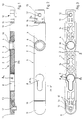
- FIG. 1 shows a door plate designed as a composite component 1 with an upper part 2 and a lower part 3.
- the lower part consists of a glass fiber reinforced polyamide and the upper part of a very smooth plastic, such as polystyrene, polypropylene, polyamide or the like.
- a very smooth plastic such as polystyrene, polypropylene, polyamide or the like.
- the fitting part 1 has a bearing bush 4 for receiving an operating element, such as a door handle or doorknob.
- the bearing bush 4 is formed on the lower part 3, so that a permanent and stable mounting of an operating member is ensured.
- the bearing bush 4 projects through the upper part 2, so that an end face 6 of the bearing bush can serve as an axial stop for the operating element, which is also formed from the stable material of the lower part 3.
- the upper part 2 forms a coaxial circular ring 7 around the bearing bush 4, which ends flush with the end face 6. This ensures an optical veneer in the area of the transition from control element to bearing bush 4.
- FIG. 2 shows the top view of the coaxial arrangement of the end face 6 of the bearing bush 4, formed from the material of the lower part 3, and the circular ring 7 of the upper part 2.
- An opposing axial stop is formed by an annular flange 18 of the bearing bush 4.
- an operating element such as a handle, provided with an expanding core with lugs engaging behind the flange, can be fixed in the axial direction.
- the expanding core can be designed so that it closes with the rear screw-on surface of the fitting part 1.
- a snap-on cover cap 11 made of the material of the upper part 2.
- the cover cap 11 covers a bore 12, the wall of which is formed by a sleeve 13 molded onto the upper part 2.
- the upper end of the fitting part 1 - on the right in FIG. 1 - is shown without a cap 11.
- the lower part 3 is also covered from the upper part 2 to the rear 3a in the end region of the covering caps 11. This results in a very simple injection molding, since the upper part 2 directly onto the lower part 3 Can be sprayed on using a mask. In addition, there is a stable bond between the upper and lower part.
- edges 3c of the lower part 3 can be encompassed by the material of the upper part 2.
- grooves 3d can also be formed in the edge regions of the undersides 3a, into which the material of the upper part 2 engages, so that it practically clasps the lower part 3.
- the cover cap 11 is designed such that it forms a flush closure to the upper part 2, as can be seen in FIG. 2, a groove 19 being provided on the edge of the upper part 2 for the cover cap 11 only for aesthetic reasons.
- recesses 16 are provided in the end region of the cover caps, into which corresponding webs of the cover caps 11 engage.
- Lugs 17 are arranged on the cover cap 11 (see FIG. 3), which partially enclose the end regions of the fitting part 1 in the engaged state and engage in corresponding recesses in the lower part 3. This ensures that the cover caps 11 engage securely on the fitting part 1.
- the fitting part 1 has a recess 8 for receiving a locking cylinder, such as a profile cylinder.
- a locking cylinder such as a profile cylinder.
- Figure 3 the lining of the wall 9 of the recess 8 through the upper part 2 can be seen. This ensures a rounded edge profile to the recess 8 at the front. Since the lower part is preferably held from the front when the upper part 2 is sprayed on, it is provided that a bolt with an annular flange covering the end face 6 of the bearing bush 4 is used for holding.
- a bolt with an annular flange covering the end face 6 of the bearing bush 4 is used for holding.
- the lower part in the upper part shape first serves a locating pin in the bearing bush 4, the contour of the locating pin corresponding to that of the bearing bush.
- a corresponding bearing pin can be arranged in the recess 8, in which case it only engages lugs 8a of the lower part 3, while the remaining space between this profiled pin and the lower part 4 is filled by the material when the upper part is sprayed. Furthermore, two retaining pins can engage in the areas of the cover caps (such as 11) on the lower part (in FIG. 3a). Finally, a retaining ring, such as a band on the above-mentioned receiving pin, can press onto the end face 6 of the bearing bush 4. By both measures, the lower part 3b is pressed flat onto the underside of the upper part shape.
- FIG. 3 shows ribs 14 which give the lower part 2 the necessary stability with the greatest possible material savings.
- the fitting part 1 shown is characterized by an extraordinarily high stability with a minimum width of 24.5 mm.
- a very appealing design of the fitting part is possible, which results in very smooth, easy-to-clean surfaces.
Landscapes
- Injection Moulding Of Plastics Or The Like (AREA)
- Finger-Pressure Massage (AREA)
- Adornments (AREA)
- Piezo-Electric Or Mechanical Vibrators, Or Delay Or Filter Circuits (AREA)
- Wing Frames And Configurations (AREA)
- Securing Of Glass Panes Or The Like (AREA)
Claims (16)
- Armature de portes ou fenêtres pour la réception d'un organe de commande, comportant une partie supérieure et une partie inférieure en matières différentes, caractérisée en ce que la partie inférieure (3) est formée d'une matière synthétique renforcée par des fibres et en ce que la partie supérieure (2) et la partie inférieure (3) constituent une pièce composite (1) monobloc, dans laquelle la partie inférieure (3) est recouverte par la matière de la partie supérieure (2).
- Armature selon la revendication 1, caractérisée en ce que la partie inférieure (3) est fabriquée à partir d'une matière synthétique par un procédé de moulage par injection.
- Armature selon la revendication 1 ou 2, caractérisée en ce que la partie inférieure (3) est formée d'une matière synthétique renforcée par des fibres de verre et/ou de céramique.
- Armature selon la revendication 3, caractérisée en ce que la partie inférieure (3) est formée d'un polyamide renforcé par des fibres.
- Armature selon l'une des revendications précédentes, caractérisée en ce que la partie inférieure (3) est réalisée sous la forme d'une construction nervurée.
- Armature selon l'une des revendications précédentes, caractérisée en ce que la partie supérieure (2) en matière synthétique est appliquée sur la partie inférieure (3) par un procédé de moulage par injection.
- Armature selon l'une des revendications précédentes, caractérisée en ce que la partie supérieure (2) forme les faces visibles de l'armature (1).
- Armature selon l'une des revendications précédentes, caractérisée en ce que la partie inférieure (3) présente un coussinet (4) pour l'organe de commande.
- Armature selon la revendication 8, caractérisée en ce que le coussinet (4) de la partie inférieure (3) pénètre dans la partie supérieure (2).
- Armature selon l'une des revendications précédentes, caractérisée en ce que la partie inférieure (3) présente un évidement (8) en forme de trou de serrure, qui est revêtu essentiellement de la matière de la partie supérieure (2).
- Armature selon l'une des revendications précédentes, caractérisée en ce que la partie supérieure (2) présente au moins un cache de recouvrement encliquetable (11) pour un moyen de fixation situé en dessous.
- Armature selon l'une des revendications précédentes, caractérisée en ce que la partie supérieure (2) présente, à chaque extrémité, un cache de recouvrement ajustable (11) pour un moyen de fixation.
- Armature selon l'une des revendications précédentes, caractérisée en ce qu'aux extrémités de l'armature (1) est prévu à chaque fois un alésage (12) pour un organe de fixation, lequel est recouvert par un cache de recouvrement (11).
- Armature selon l'une des revendications précédentes, caractérisée en ce que l'alésage (12) est constitué d'un manchon (13) formé dans la partie supérieure (2) et traversant la partie inférieure (3).
- Armature selon l'une des revendications précédentes, caractérisée en ce que le manchon (13) dépasse de la partie inférieure (3) à sa face arrière.
- Armature selon l'une des revendications précédentes, caractérisée en ce que sa largeur est inférieure à 29 mm.
Applications Claiming Priority (2)
| Application Number | Priority Date | Filing Date | Title |
|---|---|---|---|
| DE4101218A DE4101218A1 (de) | 1991-01-17 | 1991-01-17 | Beschlagteil |
| DE4101218 | 1991-01-17 |
Publications (2)
| Publication Number | Publication Date |
|---|---|
| EP0497111A1 EP0497111A1 (fr) | 1992-08-05 |
| EP0497111B1 true EP0497111B1 (fr) | 1994-10-19 |
Family
ID=6423174
Family Applications (1)
| Application Number | Title | Priority Date | Filing Date |
|---|---|---|---|
| EP92100331A Expired - Lifetime EP0497111B1 (fr) | 1991-01-17 | 1992-01-10 | Armature |
Country Status (3)
| Country | Link |
|---|---|
| EP (1) | EP0497111B1 (fr) |
| AT (1) | ATE113107T1 (fr) |
| DE (2) | DE4101218A1 (fr) |
Families Citing this family (3)
| Publication number | Priority date | Publication date | Assignee | Title |
|---|---|---|---|---|
| DE20019100U1 (de) * | 2000-11-10 | 2002-03-21 | Krecké, Edmond Dominique, Beaufort | Fenster und Tür sowie Schließeinrichtung mit erheblich verbesserter Wärmeisolation |
| IT1393485B1 (it) * | 2009-03-31 | 2012-04-27 | Gsg Int Spa | Maniglia a cremonese per infissi. |
| GB2505861A (en) * | 2012-06-22 | 2014-03-19 | John Sharples | Attachment reinforcing a window frame around the handle connection |
Family Cites Families (7)
| Publication number | Priority date | Publication date | Assignee | Title |
|---|---|---|---|---|
| DE7124601U (de) * | 1971-10-28 | Jans F | Türschild | |
| DE1728508A1 (de) * | 1967-07-20 | 1973-08-23 | Heinrich Wilke | Kunststofftuerschild mit unterteil und deckkappe |
| DE7020834U (de) * | 1970-06-04 | 1970-12-10 | Wilhelm Engstfeld Fa | Tuerbeschlag. |
| DE7028712U (de) * | 1970-07-30 | 1970-11-05 | Geldermann & Co Metallwarenfab | Tuerschild. |
| DE2222717A1 (de) * | 1972-05-09 | 1973-12-20 | Grossteinbeck Gmbh Otto | Einrichtung zum befestigen eines tuerschildes oder einer tuerrosette |
| DE7603488U1 (de) * | 1976-02-07 | 1976-07-01 | Kirchmann-Niederdrenk Kg, 5628 Heiligenhaus | Aufbohrschutzplatte |
| DE8513871U1 (de) * | 1985-05-10 | 1985-06-20 | Wilh. Engstfeld Gmbh U. Co Kg, 5628 Heiligenhaus | Türbeschlagschild |
-
1991
- 1991-01-17 DE DE4101218A patent/DE4101218A1/de not_active Withdrawn
-
1992
- 1992-01-10 AT AT92100331T patent/ATE113107T1/de not_active IP Right Cessation
- 1992-01-10 EP EP92100331A patent/EP0497111B1/fr not_active Expired - Lifetime
- 1992-01-10 DE DE59200634T patent/DE59200634D1/de not_active Expired - Fee Related
Also Published As
| Publication number | Publication date |
|---|---|
| ATE113107T1 (de) | 1994-11-15 |
| DE59200634D1 (de) | 1994-11-24 |
| EP0497111A1 (fr) | 1992-08-05 |
| DE4101218A1 (de) | 1992-07-23 |
Similar Documents
| Publication | Publication Date | Title |
|---|---|---|
| DE4037752C1 (fr) | ||
| DE9417168U1 (de) | Bausatz für ein Möbelstück | |
| EP1916361A1 (fr) | Poignée prevue pour être montée dans une ouverture | |
| DE202022002815U1 (de) | Verbesserte Inspektionsklappe | |
| DE69401247T2 (de) | Scharnieranordnung | |
| DE3874685T2 (de) | Verfahren fuer den zusammenbau einer kraftfahrzeugtuer und eine durch ein solches verfahren hergestellte tuer. | |
| EP0010763B1 (fr) | Profilé pour cadres de portes et de fenêtres ou pour des ensembles fonctionnels amovibles ou analogues d'armoires d'appareillage électrique ou analogues | |
| EP0497111B1 (fr) | Armature | |
| DE2261946A1 (de) | Beschlag fuer aus metall- oder kunststoffprofilen gefertigte fenster und tueren od.dgl | |
| EP0459987B1 (fr) | Boitier bicoque pour appareils | |
| DE2718402A1 (de) | Griff, insbesondere haltegriff fuer fahrzeuge | |
| DE3242077A1 (de) | Halterung zum befestigen eines steckers, vorzugsweise an einer flugzeugstruktur | |
| DE4028653A1 (de) | Montageplatte fuer moebelscharniere und verfahren zur herstellung derselben | |
| DE19743489C1 (de) | Bausatz für einen Fensterflügelrahmen aus Holz | |
| DE202007003765U1 (de) | Handgriff für ein Hausgerät | |
| EP0839346A1 (fr) | Dispositif de fixation d'un tableau de commande sur le bord inferieur avant d'un appareil de commande | |
| DE3704218A1 (de) | Schubladen-bausatz | |
| EP0606878A1 (fr) | Plaque de porte pour une serrure à cylindre | |
| EP0945574B1 (fr) | Charnière pour portes, fenêtres ou similaires | |
| DE19903422A1 (de) | Schließblech | |
| DE3514276A1 (de) | Scharnierverbindung fuer extruderprofile | |
| DE3109860C2 (fr) | ||
| EP0839976A2 (fr) | Gâche | |
| DE20218110U1 (de) | Beschlag und Duschabtrennung | |
| DE29717517U1 (de) | Bausatz für einen Fensterflügelrahmen aus Holz |
Legal Events
| Date | Code | Title | Description |
|---|---|---|---|
| PUAI | Public reference made under article 153(3) epc to a published international application that has entered the european phase |
Free format text: ORIGINAL CODE: 0009012 |
|
| AK | Designated contracting states |
Kind code of ref document: A1 Designated state(s): AT BE CH DE ES FR GB LI LU NL |
|
| 17P | Request for examination filed |
Effective date: 19921230 |
|
| 17Q | First examination report despatched |
Effective date: 19940324 |
|
| GRAA | (expected) grant |
Free format text: ORIGINAL CODE: 0009210 |
|
| AK | Designated contracting states |
Kind code of ref document: B1 Designated state(s): AT BE CH DE ES FR GB LI LU NL |
|
| PG25 | Lapsed in a contracting state [announced via postgrant information from national office to epo] |
Ref country code: NL Effective date: 19941019 Ref country code: GB Effective date: 19941019 Ref country code: ES Free format text: THE PATENT HAS BEEN ANNULLED BY A DECISION OF A NATIONAL AUTHORITY Effective date: 19941019 Ref country code: BE Effective date: 19941019 |
|
| REF | Corresponds to: |
Ref document number: 113107 Country of ref document: AT Date of ref document: 19941115 Kind code of ref document: T |
|
| REF | Corresponds to: |
Ref document number: 59200634 Country of ref document: DE Date of ref document: 19941124 |
|
| PG25 | Lapsed in a contracting state [announced via postgrant information from national office to epo] |
Ref country code: AT Effective date: 19950110 |
|
| REG | Reference to a national code |
Ref country code: CH Ref legal event code: PUE Owner name: NT NORMBAU BESCHLAEGE UND AUSSTATTUNG GMBH |
|
| RAP2 | Party data changed (patent owner data changed or rights of a patent transferred) |
Owner name: NT NORMBAU BESCHLAEGE UND AUSTATTUNG GMBH |
|
| PG25 | Lapsed in a contracting state [announced via postgrant information from national office to epo] |
Ref country code: LU Free format text: LAPSE BECAUSE OF NON-PAYMENT OF DUE FEES Effective date: 19950131 Ref country code: LI Effective date: 19950131 Ref country code: CH Effective date: 19950131 |
|
| ET | Fr: translation filed | ||
| NLV1 | Nl: lapsed or annulled due to failure to fulfill the requirements of art. 29p and 29m of the patents act | ||
| GBV | Gb: ep patent (uk) treated as always having been void in accordance with gb section 77(7)/1977 [no translation filed] |
Effective date: 19941019 |
|
| PLBE | No opposition filed within time limit |
Free format text: ORIGINAL CODE: 0009261 |
|
| STAA | Information on the status of an ep patent application or granted ep patent |
Free format text: STATUS: NO OPPOSITION FILED WITHIN TIME LIMIT |
|
| REG | Reference to a national code |
Ref country code: CH Ref legal event code: PL |
|
| 26N | No opposition filed | ||
| REG | Reference to a national code |
Ref country code: FR Ref legal event code: TP |
|
| PGFP | Annual fee paid to national office [announced via postgrant information from national office to epo] |
Ref country code: FR Payment date: 20060119 Year of fee payment: 15 |
|
| PGFP | Annual fee paid to national office [announced via postgrant information from national office to epo] |
Ref country code: DE Payment date: 20060121 Year of fee payment: 15 |
|
| PG25 | Lapsed in a contracting state [announced via postgrant information from national office to epo] |
Ref country code: DE Free format text: LAPSE BECAUSE OF NON-PAYMENT OF DUE FEES Effective date: 20070801 |
|
| REG | Reference to a national code |
Ref country code: FR Ref legal event code: ST Effective date: 20070930 |
|
| PG25 | Lapsed in a contracting state [announced via postgrant information from national office to epo] |
Ref country code: FR Free format text: LAPSE BECAUSE OF NON-PAYMENT OF DUE FEES Effective date: 20070131 |