EP0606907B1 - Rouleau de chargement pour un appareil de formation d'images - Google Patents
Rouleau de chargement pour un appareil de formation d'images Download PDFInfo
- Publication number
- EP0606907B1 EP0606907B1 EP19940100436 EP94100436A EP0606907B1 EP 0606907 B1 EP0606907 B1 EP 0606907B1 EP 19940100436 EP19940100436 EP 19940100436 EP 94100436 A EP94100436 A EP 94100436A EP 0606907 B1 EP0606907 B1 EP 0606907B1
- Authority
- EP
- European Patent Office
- Prior art keywords
- charging roller
- weight
- surface layer
- occurred
- parts
- Prior art date
- Legal status (The legal status is an assumption and is not a legal conclusion. Google has not performed a legal analysis and makes no representation as to the accuracy of the status listed.)
- Expired - Lifetime
Links
- 239000010410 layer Substances 0.000 claims description 37
- 239000002344 surface layer Substances 0.000 claims description 32
- 239000000126 substance Substances 0.000 claims description 24
- YCKRFDGAMUMZLT-UHFFFAOYSA-N Fluorine atom Chemical compound [F] YCKRFDGAMUMZLT-UHFFFAOYSA-N 0.000 claims description 16
- 229910052731 fluorine Inorganic materials 0.000 claims description 16
- 239000011737 fluorine Substances 0.000 claims description 16
- 229920005558 epichlorohydrin rubber Polymers 0.000 claims description 10
- RTZKZFJDLAIYFH-UHFFFAOYSA-N Diethyl ether Chemical compound CCOCC RTZKZFJDLAIYFH-UHFFFAOYSA-N 0.000 claims description 8
- 229920001577 copolymer Polymers 0.000 claims description 7
- OIXNFJTTYAIBNF-UHFFFAOYSA-N 2-(chloromethyl)oxirane;oxirane Chemical compound C1CO1.ClCC1CO1 OIXNFJTTYAIBNF-UHFFFAOYSA-N 0.000 claims description 5
- QYKIQEUNHZKYBP-UHFFFAOYSA-N Vinyl ether Chemical compound C=COC=C QYKIQEUNHZKYBP-UHFFFAOYSA-N 0.000 claims description 5
- 229920006027 ternary co-polymer Polymers 0.000 claims description 5
- 239000005977 Ethylene Substances 0.000 claims description 3
- 125000002887 hydroxy group Chemical group [H]O* 0.000 claims description 3
- 239000012948 isocyanate Substances 0.000 claims description 3
- 150000002513 isocyanates Chemical class 0.000 claims description 3
- 238000004132 cross linking Methods 0.000 claims description 2
- 239000003973 paint Substances 0.000 description 20
- 239000011347 resin Substances 0.000 description 16
- 229920005989 resin Polymers 0.000 description 16
- 239000000203 mixture Substances 0.000 description 14
- YXFVVABEGXRONW-UHFFFAOYSA-N Toluene Chemical compound CC1=CC=CC=C1 YXFVVABEGXRONW-UHFFFAOYSA-N 0.000 description 9
- 150000001875 compounds Chemical class 0.000 description 9
- QIQXTHQIDYTFRH-UHFFFAOYSA-N octadecanoic acid Chemical compound CCCCCCCCCCCCCCCCCC(O)=O QIQXTHQIDYTFRH-UHFFFAOYSA-N 0.000 description 8
- CBENFWSGALASAD-UHFFFAOYSA-N Ozone Chemical compound [O-][O+]=O CBENFWSGALASAD-UHFFFAOYSA-N 0.000 description 7
- 239000002245 particle Substances 0.000 description 7
- 235000021355 Stearic acid Nutrition 0.000 description 6
- 238000007598 dipping method Methods 0.000 description 6
- 230000001788 irregular Effects 0.000 description 6
- OQCDKBAXFALNLD-UHFFFAOYSA-N octadecanoic acid Natural products CCCCCCCC(C)CCCCCCCCC(O)=O OQCDKBAXFALNLD-UHFFFAOYSA-N 0.000 description 6
- 239000008117 stearic acid Substances 0.000 description 6
- 230000000052 comparative effect Effects 0.000 description 5
- 239000007787 solid Substances 0.000 description 5
- VTYYLEPIZMXCLO-UHFFFAOYSA-L Calcium carbonate Chemical compound [Ca+2].[O-]C([O-])=O VTYYLEPIZMXCLO-UHFFFAOYSA-L 0.000 description 4
- HCHKCACWOHOZIP-UHFFFAOYSA-N Zinc Chemical compound [Zn] HCHKCACWOHOZIP-UHFFFAOYSA-N 0.000 description 4
- 238000000151 deposition Methods 0.000 description 4
- KUAZQDVKQLNFPE-UHFFFAOYSA-N thiram Chemical compound CN(C)C(=S)SSC(=S)N(C)C KUAZQDVKQLNFPE-UHFFFAOYSA-N 0.000 description 4
- 238000004073 vulcanization Methods 0.000 description 4
- 239000011701 zinc Substances 0.000 description 4
- 229910052725 zinc Inorganic materials 0.000 description 4
- 239000004215 Carbon black (E152) Substances 0.000 description 3
- 230000007547 defect Effects 0.000 description 3
- 229920001971 elastomer Polymers 0.000 description 3
- 229930195733 hydrocarbon Natural products 0.000 description 3
- 150000002430 hydrocarbons Chemical class 0.000 description 3
- 238000005259 measurement Methods 0.000 description 3
- 239000002904 solvent Substances 0.000 description 3
- 230000003746 surface roughness Effects 0.000 description 3
- NTIZESTWPVYFNL-UHFFFAOYSA-N Methyl isobutyl ketone Chemical compound CC(C)CC(C)=O NTIZESTWPVYFNL-UHFFFAOYSA-N 0.000 description 2
- UIHCLUNTQKBZGK-UHFFFAOYSA-N Methyl isobutyl ketone Natural products CCC(C)C(C)=O UIHCLUNTQKBZGK-UHFFFAOYSA-N 0.000 description 2
- XAGFODPZIPBFFR-UHFFFAOYSA-N aluminium Chemical compound [Al] XAGFODPZIPBFFR-UHFFFAOYSA-N 0.000 description 2
- 229910052782 aluminium Inorganic materials 0.000 description 2
- 229920006125 amorphous polymer Polymers 0.000 description 2
- 229910000019 calcium carbonate Inorganic materials 0.000 description 2
- 230000015556 catabolic process Effects 0.000 description 2
- 239000000470 constituent Substances 0.000 description 2
- 230000008021 deposition Effects 0.000 description 2
- 238000000034 method Methods 0.000 description 2
- 239000004848 polyfunctional curative Substances 0.000 description 2
- 229910001220 stainless steel Inorganic materials 0.000 description 2
- 239000010935 stainless steel Substances 0.000 description 2
- RYGMFSIKBFXOCR-UHFFFAOYSA-N Copper Chemical compound [Cu] RYGMFSIKBFXOCR-UHFFFAOYSA-N 0.000 description 1
- 229920002943 EPDM rubber Polymers 0.000 description 1
- BRLQWZUYTZBJKN-UHFFFAOYSA-N Epichlorohydrin Chemical compound ClCC1CO1 BRLQWZUYTZBJKN-UHFFFAOYSA-N 0.000 description 1
- JOYRKODLDBILNP-UHFFFAOYSA-N Ethyl urethane Chemical compound CCOC(N)=O JOYRKODLDBILNP-UHFFFAOYSA-N 0.000 description 1
- CTQNGGLPUBDAKN-UHFFFAOYSA-N O-Xylene Chemical compound CC1=CC=CC=C1C CTQNGGLPUBDAKN-UHFFFAOYSA-N 0.000 description 1
- 229920005603 alternating copolymer Polymers 0.000 description 1
- 239000003795 chemical substances by application Substances 0.000 description 1
- 238000010276 construction Methods 0.000 description 1
- 238000007334 copolymerization reaction Methods 0.000 description 1
- 239000011889 copper foil Substances 0.000 description 1
- 230000006866 deterioration Effects 0.000 description 1
- 230000002542 deteriorative effect Effects 0.000 description 1
- 238000011161 development Methods 0.000 description 1
- 239000000428 dust Substances 0.000 description 1
- 238000003912 environmental pollution Methods 0.000 description 1
- 238000011156 evaluation Methods 0.000 description 1
- 239000004615 ingredient Substances 0.000 description 1
- IQPQWNKOIGAROB-UHFFFAOYSA-N isocyanate group Chemical group [N-]=C=O IQPQWNKOIGAROB-UHFFFAOYSA-N 0.000 description 1
- 239000000463 material Substances 0.000 description 1
- 238000012986 modification Methods 0.000 description 1
- 230000004048 modification Effects 0.000 description 1
- 229920002635 polyurethane Polymers 0.000 description 1
- 239000004814 polyurethane Substances 0.000 description 1
- 229920005749 polyurethane resin Polymers 0.000 description 1
- 239000008096 xylene Substances 0.000 description 1
Images
Classifications
-
- G—PHYSICS
- G03—PHOTOGRAPHY; CINEMATOGRAPHY; ANALOGOUS TECHNIQUES USING WAVES OTHER THAN OPTICAL WAVES; ELECTROGRAPHY; HOLOGRAPHY
- G03G—ELECTROGRAPHY; ELECTROPHOTOGRAPHY; MAGNETOGRAPHY
- G03G15/00—Apparatus for electrographic processes using a charge pattern
- G03G15/02—Apparatus for electrographic processes using a charge pattern for laying down a uniform charge, e.g. for sensitising; Corona discharge devices
- G03G15/0208—Apparatus for electrographic processes using a charge pattern for laying down a uniform charge, e.g. for sensitising; Corona discharge devices by contact, friction or induction, e.g. liquid charging apparatus
- G03G15/0216—Apparatus for electrographic processes using a charge pattern for laying down a uniform charge, e.g. for sensitising; Corona discharge devices by contact, friction or induction, e.g. liquid charging apparatus by bringing a charging member into contact with the member to be charged, e.g. roller, brush chargers
- G03G15/0233—Structure, details of the charging member, e.g. chemical composition, surface properties
Definitions
- the present invention relates to a charging roller as defined in the preamble of claim 1, i.e. according to EP-A-0 406 834, for a copier, printer, facsimile transceiver or similar image forming apparatus and, more particularly, to a charging roller for uniformly charging the surface of a photoconductive element, or image carrier, during a sequence of image forming steps.
- a corona discharger effectively charges the surface of a photoconductive element uniformly to a predetermined potential.
- a corona discharger needs a high tension power source and generates ozone during discharge. Ozone generated in a great amount would not only pollute the environment but also aggravate the deterioration of a charging member as well as the photoconductive element.
- This type of charging device has a charging roller held in contact with and driven by a photoconductive drum.
- the charging roller has a metallic core. As a voltage is applied from a power source to the core of the charging roller, the roller charges the surface of the drum. With the charging roller, it is possible to lower the required voltage of the power source and to reduce the amount of ozone ascribable to charging. In addition, the charging roller prevents dust particles from electrostatically depositing on a corona wire and eliminates the need for a high tension power source.
- Japanese Patent Laid-Open Publication JP-A-63-149668 teaches that the uniformity of charge is noticeably improved when an AC voltage having a peak-to-peak voltage more than twice as high as a charge start voltage (V TH ) is superposed in the event of application of a DC voltage.
- V TH charge start voltage
- this kind of scheme needs an AC power source in addition to a DC power source for superposing the AC voltage on the DC voltage, increasing the cost of the apparatus.
- a great amount of AC current not contributing to the charge potential of the photoconductive element is wastefully consumed. This not only increases the running cost of the apparatus but also generates a great amount of ozone, bringing about the previously stated critical problems.
- EP-A-0 406 834 refers to a charging member including a base layer and a surface layer.
- the base layer has a resistivity of 10 0 to 10 11 ⁇ .cm.
- the surface layer includes 30% by wt. or higher and more preferably 50% by wt. or higher polyurethane resin, which is made of an isocyanate group and a hydroxyl group and particular care is involved to satisfy a relationship between the two ingredients of the polyurethane.
- the volume resistivity of the surface layer is adjusted to be within the range of 10 6 ⁇ .cm to 10 12 ⁇ .cm.
- an electrically conductive elastic layer and a resistance layer on an electrically conductive base are arranged to provide a charging roller for charging a photoconductive element.
- the conductive elastic layer has a resistivity of about 10 1 to 10 5 ⁇ .cm and the surface layer has a resistivity of about 10 6 ⁇ .cm to 10 12 ⁇ .cm. Since this elastic layer is conductive, a relatively thick surface layer is necessary to avoid short circuiting between the elastic layer and a body to be charged, because the thickness of the surface layer influences the characteristics of the surface layer against breakdown between the elastic layer and a body to be charged much more than the resistance of the surface layer.
- an object of the present invention to provide a charging roller for an image forming apparatus capable of reducing the cost of the apparatus itself, power source cost, and generation of ozone to thereby prevent a charging member and a photoconductive element from deteriorating and avoid environmental pollution.
- a charging roller for charging a photoconductive element included in an image forming apparatus of the present invention comprises the features set forth in claim 1.
- Embodiments of the present invention are defined by the subclaims.
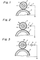
- the charging device 1 has a charging roller 2 held in contact with an image carrier implemented as a photoconductive drum 3 by way of example. While the charging roller 2 is in rotation, a high-tension DC voltage is applied from a DC power source 7 to the roller 2 to cause it to charge the drum 3.
- the charge roller 2 is made up of a metallic core 4, a conductive elastic layer 15 formed on the core 4 and having NBR or conductive particles dispersed therein, and a fluorine-based non-adhering film 10 provided with conductivity.
- the problem with this kind of charge roller 2 is that irregularity in electric characteristic is so great, the charge deposited on the drum 3 via the conductive elastic layer 15 is irregular. As a result, the background of an image is contaminated at a period coincident with the roller period.
- FIG. 3 shows a charging device using another conventional charging roller elaborated to eliminate the above problem.
- the same or similar constituent parts as or to the parts shown in FIG. 2 are designated by the same reference numerals, and a detailed description thereof will not be made in order to avoid redundancy.
- the charging roller 2 has an elastic layer 25 formed on the metallic core 4 and made of, for example, NBR, urethane or EPDM.
- a surface layer 11 is formed on the elastic layer 25 and has a conductive substance dispersed therein. The surface layer 11 is held in contact with the core 4.
- the DC power source 7 applies an AC-biased. DC voltage to the core 4.
- the AC voltage biasing the DC voltage is provided with a peak-to-peak voltage twice as high as a charge start voltage to occur at the time when the DC voltage is applied.
- an AC power source 8 is necessary in addition to the DC power source 7 and results in an extra cost, in that a great amount of AC current which does not contribute to the charge potential of the drum 3 is wastefully consumed, and in that the AC current generates harmful ozone, as discussed earlier.
- a charging roller embodying the present invention and a charging device implemented therewith will be described which are free from the above-described problems.
- the same or similar constituent parts as or to the parts shown in FIGS. 2 and 3 are designated by the same reference numerals, and a detailed description thereof will not be made in order to avoid redundancy.
- a charging roller 2 has a metallic core 4, an elastic layer 5 formed on the core 4, and a surface layer 6 formed on the elastic layer 5.
- a DC power source 7 applies a high-tension negative DC voltage of 1.3 kV to 1.6 kV to cause it to charge a photoconductive drum 3.
- the elastic layer 5 is made of epichlorohydrin rubber having a medium electric resistance and in which conductive particles are not dispersed.
- the epichlorohydrin rubber may be implemented by a binary copolymer of epichlorohydrin-ethylene oxide or a ternary copolymer of epichlorohydrin-ethylene oxide arylglycidyl ether.
- the surface layer 6 is constituted by a mixture of epichlorohydrin rubber applied to the elastic layer 5 and non-adhering fluorine-based resin. This is to enhance the non-adhering property of the surface of the charging roller 2 against the deposition of toner particles.
- the fluorine-based resin is an amorphous polymer soluble to a solvent and produced by the copolymerization reaction of fluoroolefin and hydrocarbon-based vinyl ether.
- Kojima et al Japanese of the Institute of Organic Synthetic Chemical Engineers of Japan
- the fluorine-based resin has a relatively low fluorine content, i.e., 25 wt% to 32 wt%.
- the resin of this kind is an alternating copolymer in which fluoroolefin and hydrocarbon vinyl ether alternate with each other, the fluoroolefin portions which are thermochemically stable and regularly arranged protect the unstable hydrocarbon-based vinyl ether portions electronically and sterically. Hence, such a resin is chemically stable and durable.
- the resin, or amorphous polymer is soluble to a solvent and, therefore, has to be crosslinked after application, thereby providing the resulting film with resistivity to solvents.
- hydroxyl group-containing vinyl ether which is highly reactive is copolymerized with fluoroolefin so as to produce a resin structure which promotes easy crosslinking by isocyanate.
- the above structure allows the elastic layer 5 to function with stability and uniformity as an electric resistance body and has a small electrostatic capacity. Therefore, even when AC is superposed on DC, the uniform charging ability is not improved to a noticeable degree. As a result, it is not necessary to superpose AC on DC, i.e., high-tension DC voltage should only be applied.
- the shaft was vulcanized at 170°C for 10 minutes and again vulcanized at 200°C for 2 hours.
- the surface of the resulting roller was machined to have a roller diameter of 12 mm.
- the roller was measured to have a medium electric resistance and, physically, a volume resistivity of 2 x 10 8 ⁇ cm, rubber hardness of 33° (JIS A), and surface roughness of 3 ⁇ m ⁇ Rz.
- the mixture was kneaded to prepare a compound having a uniform composition.
- 2.5 parts by weight of the compound was dissolved in a mixture solution of 48.8 parts by weight of toluene and 48.8 parts by weight of 4-methyl-2-pentanone, thereby producing an epichlorohydrin rubber solution containing 2.5 % of solids (paint A-1).
- 22 parts by weight of solvent-soluble fluorine resin Liiflon LF-601C major agent available from Asahi Glass Co. Ltd. (Japan)
- isocyanate-based hardener Liiflon LF-601C hardener also available from Asahi Glass Co., Ltd.
- the charging roller 2 fabricated by the above procedure was substituted for a primary corona charger included in a positive-to-positive development type copier (FT3300 available from Ricoh Co.Ltd. (Japan)). In this condition, the roller 2 was held in contact with and rotated by the drum 3 while a DC voltage of 1.4 kV was applied to the core 4 thereof as a primary charge voltage.
- Table 1 which is shown below, indicates a light potential measured with the charging roller 2 together with the result of evaluation of an image in a row labeled Ex. (Example) 1. Even after the copier was operated to produce 5,000 copies, the potential and image were free from defects.
- each sample was left in a 20°C, 60 % RH atmosphere for 16 hours, use was made of an electrometer 610C, and an electrode for measurement was implemented by a tape of copper foil (No. 1245 available from 3M). Further, to measure the volume resistivity of the surface layer alone, the material constituting it was painted on a thin aluminum plate (0.2 mm thick) to a thickness of about 50 ⁇ m. Then, the aluminum plate was left in a 20°C, 60RH atmosphere for 16 hours; for the measurement, use was made of a resistance measuring cell (16008A available from YHP) and above-mentioned electrometer 610C.
- a resistance measuring cell 16008A available from YHP
- Example 2 is identical with Example 1 described above except that the surface layer 6 was 90 ⁇ m thick.
- Example 3 to produce the elastic layer 5, there were mixed 100 parts by weight of epichlorohydrin rubber of binary copolymer of epichlorohydrin-ethylene oxide (Epichromer C available from Daiso Co. Ltd. (Japan)), 30 parts by weight of more volatile calcium carbonate, 10 parts by weight of Sub (Neo factice GT available from Tenma Sub Chemicals Ltd. (Japan)), 5 parts by weight of zinc flower (Sazex I, Sakai Chemicals, Ltd. (Japan)), 0.5 part by weight of stearic acid (Stearic Acid SA-200, Asahi Denka Co., Ltd.
- Example 3 to form the surface layer 6, there were mixed and kneaded 100 parts by weight of epichlorohydrin rubber of binary copolymer (Epichlomer C available from Daiso), 0.5 part by weight of stearic acid, 5 parts by weight of zinc flower, 1 part of vulcanization accelerator (Nocceler TT available from Ouchi Shinko Chemicals Inc. (Japan)), 1.5 parts by weight of Nocceler DM also available from Ouchi Shinko Chemicals, and 0.25 part by weight of Sulfax H available from Tsurumi Chemicals, thereby preparing a compound having a uniform composition.
- Epichlorohydrin rubber of binary copolymer (Epichlomer C available from Daiso)
- stearic acid 0.5 part by weight of stearic acid
- 5 parts by weight of zinc flower 1 part of vulcanization accelerator (Nocceler TT available from Ouchi Shinko Chemicals Inc. (Japan)
- Nocceler DM also available
- the mixture paint was coated on the elastic layer 5 by dipping, and then dried at 160°C for 30 minutes to form a 6 ⁇ m thick layer.
- the surface layer 6 had a volume resistivity of 1 x 10 10 ⁇ cm.
- the properties of the roller 2 are shown in Example 4 of Table 1.
- Example 5 only the paint B was coated on the elastic layer 5 of Example 1 by dipping and then dried at 100°C for 30 minutes to form an 8 ⁇ m thick surface layer 6.
- the layer 6 had a volume resistivity of 2 x 10 14 ⁇ cm.
- the properties of the resulting roller 2 are indicated in Example 5 of Table 1.
- Example 6 only the paint B was coated on the elastic layer 5 of Example 3 by dipping and then dried at 100°C for 30 minutes to form a 5 ⁇ m thick surface layer.
- the properties of the resulting roller 2 are shown in Example 6 of Table 1.
- Comparative Example (Comp. Ex.) 1 is representative of a case wherein a roller 2 had the elastic layer 5 of Example 1 and did not have the surface layer 6. It will be seen that when 5,000 copies are produced, irregular image density and toner filming occur.
- Comparative Example 2 is identical with Example 1 except that the surface layer 6 was 230 ⁇ m thick.
- the roller 2 had a hardness of 48° (JIS A).
- Comparative Example 3 only the paint B was coated on the elastic layer 5 of Example 4 by dipping and then dried at 100°C for 30 minutes to form a 30 ⁇ m thick surface layer 6. It will be seen that irregular image density and toner filming occur.
- Comparative Example 4 is identical with Example 6 except that the surface layer 6 was 11 ⁇ m thick.
- charge potential and, therefore, image density is slightly lowered, as Table 1 indicates.
- Comparative Example 5 is identical with Example 6 except that the surface layer 6 was 15 ⁇ m thick. In this case, charge potential and, therefore, image density is further lowered, as Table 1 also indicates.
- the present invention provides a charging roller having various unprecedented advantages, as enumerated below.
Landscapes
- Physics & Mathematics (AREA)
- Engineering & Computer Science (AREA)
- Plasma & Fusion (AREA)
- General Physics & Mathematics (AREA)
- Electrostatic Charge, Transfer And Separation In Electrography (AREA)
- Registering, Tensioning, Guiding Webs, And Rollers Therefor (AREA)
- Delivering By Means Of Belts And Rollers (AREA)
- Sheets, Magazines, And Separation Thereof (AREA)
- Rolls And Other Rotary Bodies (AREA)
Claims (3)
- Rouleau (2) de charge d'un élément photoconducteur (3) incorporé dans un appareil de formation d'images, comprenant :caractérisé par les propriétés suivantes :une couche élastique (5) formée d'une substance ayant une résistivité électrique en volume moyenne comprise dans une plage allant d'environ 7.107 à 2.108 W.cm, etune couche de surface (6) formée sur la couche élastique (5),a) la couche de surface (6) est formée d'une substance qui n'adhère pas à un développateur et qui a une propriété de défaut d'adhérence supérieure à celle de la substance ayant une résistivité électrique en volume moyenne, etb) la substance ayant une résistivité en volume moyenne est essentiellement constituée d'un caoutchouc d'épichlorhydrine sous forme d'un copolymère ternaire d'épichlorhydrine, d'oxyde d'éthylène et d'éther arylglycidylique ou d'un copolymère binaire d'épichlorhydrine et d'oxyde d'éthylène ou d'une combinaison de tels polymères.
- Rouleau de charge selon la revendication 1, dans lequel la couche de surface a une épaisseur de 5 à 10 µm.
- Rouleau de charge selon l'une des revendications 1 et 2, dans lequel la substance non adhérente est un copolymère réticulé contenant du fluor, produit par réticulation par un isocyanate d'un copolymère contenant du fluor qui est constitué d'une oléfine fluorée et d'un éther vinylique contenant un groupe hydroxyle.
Priority Applications (1)
| Application Number | Priority Date | Filing Date | Title |
|---|---|---|---|
| EP97107365A EP0810486B1 (fr) | 1993-01-13 | 1994-01-13 | Rouleau de chargement pour un appareil de formation d'images |
Applications Claiming Priority (4)
| Application Number | Priority Date | Filing Date | Title |
|---|---|---|---|
| JP367593 | 1993-01-13 | ||
| JP3675/93 | 1993-01-13 | ||
| JP27059093A JPH06266206A (ja) | 1993-01-13 | 1993-10-28 | 帯電ローラ |
| JP270590/93 | 1993-10-28 |
Related Child Applications (1)
| Application Number | Title | Priority Date | Filing Date |
|---|---|---|---|
| EP97107365A Division EP0810486B1 (fr) | 1993-01-13 | 1994-01-13 | Rouleau de chargement pour un appareil de formation d'images |
Publications (2)
| Publication Number | Publication Date |
|---|---|
| EP0606907A1 EP0606907A1 (fr) | 1994-07-20 |
| EP0606907B1 true EP0606907B1 (fr) | 1999-04-21 |
Family
ID=26337309
Family Applications (2)
| Application Number | Title | Priority Date | Filing Date |
|---|---|---|---|
| EP97107365A Expired - Lifetime EP0810486B1 (fr) | 1993-01-13 | 1994-01-13 | Rouleau de chargement pour un appareil de formation d'images |
| EP19940100436 Expired - Lifetime EP0606907B1 (fr) | 1993-01-13 | 1994-01-13 | Rouleau de chargement pour un appareil de formation d'images |
Family Applications Before (1)
| Application Number | Title | Priority Date | Filing Date |
|---|---|---|---|
| EP97107365A Expired - Lifetime EP0810486B1 (fr) | 1993-01-13 | 1994-01-13 | Rouleau de chargement pour un appareil de formation d'images |
Country Status (4)
| Country | Link |
|---|---|
| EP (2) | EP0810486B1 (fr) |
| JP (1) | JPH06266206A (fr) |
| DE (2) | DE69433430T2 (fr) |
| ES (2) | ES2208783T3 (fr) |
Families Citing this family (18)
| Publication number | Priority date | Publication date | Assignee | Title |
|---|---|---|---|---|
| US5610795A (en) * | 1994-08-01 | 1997-03-11 | Xerox Corporation | Self biasing charging member |
| EP0708382B1 (fr) | 1994-10-18 | 2002-01-30 | Canon Kabushiki Kaisha | Procédé de refabrication d'un membre de charge |
| JP3346970B2 (ja) * | 1994-11-22 | 2002-11-18 | 日本ゼオン株式会社 | ゴムロール、ゴム組成物、及び画像形成装置 |
| US5625858A (en) * | 1995-01-18 | 1997-04-29 | Canon Kabushiki Kaisha | Contact charging member, process for producing same and electrophotographic apparatus using same |
| JP3028057B2 (ja) * | 1996-02-21 | 2000-04-04 | 富士ゼロックス株式会社 | 帯電部材 |
| US5849399A (en) * | 1996-04-19 | 1998-12-15 | Xerox Corporation | Bias transfer members with fluorinated carbon filled fluoroelastomer outer layer |
| US6141516A (en) * | 1996-06-28 | 2000-10-31 | Xerox Corporation | Fluorinated carbon filled fluoroelastomer outer layer |
| JP3598718B2 (ja) * | 1997-03-25 | 2004-12-08 | 東海ゴム工業株式会社 | 半導電性ロール |
| US6558781B1 (en) | 1999-07-12 | 2003-05-06 | Canon Kabushiki Kaisha | Conductive roller, process cartridge and image forming apparatus |
| US6620476B2 (en) | 1999-08-13 | 2003-09-16 | Xerox Corporation | Nonbleeding fluorinated carbon and zinc oxide filled layer for bias charging member |
| US6203855B1 (en) | 1999-08-13 | 2001-03-20 | Xerox Corporation | Process for preparing nonbleeding fluorinated carbon and zinc oxide filler layer for bias charging member |
| EP1156388A1 (fr) | 2000-05-16 | 2001-11-21 | Hokushin Corporation | Elément de chargement |
| US8483591B2 (en) | 2009-08-27 | 2013-07-09 | Xerox Corporation | Bias charging overcoat |
| JP5471176B2 (ja) * | 2009-08-28 | 2014-04-16 | 富士ゼロックス株式会社 | 導電性ローラ用組成物、導電性ローラ、帯電装置、画像形成装置およびプロセスカートリッジならびに導電性ローラの製造方法 |
| US8649704B2 (en) | 2009-11-20 | 2014-02-11 | Xerox Corporation | Bias charging overcoat |
| US8768219B2 (en) | 2009-11-20 | 2014-07-01 | Xerox Corporation | Bias charging overcoat |
| US9442451B2 (en) | 2014-11-28 | 2016-09-13 | Canon Kabushiki Kaisha | Electroconductive member for electrophotography, process cartridge, and electrophotographic image-forming apparatus |
| US10416588B2 (en) | 2016-10-31 | 2019-09-17 | Canon Kabushiki Kaisha | Charging member, process cartridge, electrophotographic image forming apparatus, and method for manufacturing charging member |
Family Cites Families (7)
| Publication number | Priority date | Publication date | Assignee | Title |
|---|---|---|---|---|
| US4727453A (en) * | 1986-12-22 | 1988-02-23 | Xerox Corporation | Alternating current inductive charging of a photoreceptor |
| JP2575209B2 (ja) * | 1989-07-05 | 1997-01-22 | キヤノン株式会社 | 電子写真用帯電部材および電子写真装置 |
| JPH0789249B2 (ja) * | 1989-09-14 | 1995-09-27 | キヤノン株式会社 | 画像形成装置 |
| JP2765660B2 (ja) * | 1990-07-20 | 1998-06-18 | キヤノン株式会社 | 帯電用部材 |
| JP3056273B2 (ja) * | 1991-03-28 | 2000-06-26 | キヤノン株式会社 | 帯電用部材 |
| JP3053246B2 (ja) * | 1991-04-10 | 2000-06-19 | 株式会社リコー | 半導電性ローラ |
| US5270768A (en) * | 1991-04-24 | 1993-12-14 | Canon Kabushiki Kaisha | Charging member containing reduced titanium oxide and device using same |
-
1993
- 1993-10-28 JP JP27059093A patent/JPH06266206A/ja active Pending
-
1994
- 1994-01-13 ES ES97107365T patent/ES2208783T3/es not_active Expired - Lifetime
- 1994-01-13 EP EP97107365A patent/EP0810486B1/fr not_active Expired - Lifetime
- 1994-01-13 ES ES94100436T patent/ES2131593T3/es not_active Expired - Lifetime
- 1994-01-13 DE DE1994633430 patent/DE69433430T2/de not_active Expired - Lifetime
- 1994-01-13 EP EP19940100436 patent/EP0606907B1/fr not_active Expired - Lifetime
- 1994-01-13 DE DE1994617931 patent/DE69417931T2/de not_active Expired - Lifetime
Also Published As
| Publication number | Publication date |
|---|---|
| EP0810486A2 (fr) | 1997-12-03 |
| DE69417931T2 (de) | 1999-09-16 |
| EP0810486B1 (fr) | 2003-12-17 |
| EP0606907A1 (fr) | 1994-07-20 |
| DE69433430T2 (de) | 2004-10-07 |
| ES2131593T3 (es) | 1999-08-01 |
| DE69417931D1 (de) | 1999-05-27 |
| EP0810486A3 (fr) | 1998-04-15 |
| ES2208783T3 (es) | 2004-06-16 |
| DE69433430D1 (de) | 2004-01-29 |
| JPH06266206A (ja) | 1994-09-22 |
Similar Documents
| Publication | Publication Date | Title |
|---|---|---|
| EP0606907B1 (fr) | Rouleau de chargement pour un appareil de formation d'images | |
| US5602712A (en) | Contact charging method and apparatus | |
| US5786091A (en) | Charge roller for an image forming apparatus | |
| US5312662A (en) | Conductive roll | |
| EP1031888B1 (fr) | Elément de chargement, cartouche de traitement et appareil de production d' images | |
| JP3832057B2 (ja) | 現像ローラの製造方法 | |
| US5604031A (en) | Electrically conductive roll whose base layer is formed of ion-conductive elastic material | |
| US7072604B2 (en) | Electro-conductive roll and image-forming apparatus using the same | |
| US5792533A (en) | Electrostatic charging roller | |
| JP2003221474A (ja) | 導電性部材 | |
| US6001454A (en) | Charging member and electrophotographic apparatus using the same | |
| JP3053246B2 (ja) | 半導電性ローラ | |
| JPH10213948A (ja) | 帯電用部材 | |
| JPH07164571A (ja) | 帯電ローラ | |
| US6175709B1 (en) | Toner support and image forming apparatus | |
| JP3055463B2 (ja) | 導電性帯電部材 | |
| JPH05107874A (ja) | 半導電性ローラ | |
| US5529842A (en) | Charge roll for electrophotography | |
| JP3284626B2 (ja) | 帯電部材 | |
| JPH10148997A (ja) | 帯電ローラ | |
| JP3333069B2 (ja) | 帯電部材 | |
| JPH06324553A (ja) | 帯電用部材及びこれを用いた帯電装置 | |
| JPH06324554A (ja) | 帯電用部材及びこれを用いた帯電装置 | |
| JPH02311867A (ja) | 導電性ロール | |
| JP2005215177A (ja) | 帯電部材、画像形成装置、帯電方法およびプロセスカートリッジ |
Legal Events
| Date | Code | Title | Description |
|---|---|---|---|
| PUAI | Public reference made under article 153(3) epc to a published international application that has entered the european phase |
Free format text: ORIGINAL CODE: 0009012 |
|
| 17P | Request for examination filed |
Effective date: 19940113 |
|
| AK | Designated contracting states |
Kind code of ref document: A1 Designated state(s): DE ES FR GB IT |
|
| 17Q | First examination report despatched |
Effective date: 19941012 |
|
| GRAG | Despatch of communication of intention to grant |
Free format text: ORIGINAL CODE: EPIDOS AGRA |
|
| GRAG | Despatch of communication of intention to grant |
Free format text: ORIGINAL CODE: EPIDOS AGRA |
|
| GRAH | Despatch of communication of intention to grant a patent |
Free format text: ORIGINAL CODE: EPIDOS IGRA |
|
| GRAH | Despatch of communication of intention to grant a patent |
Free format text: ORIGINAL CODE: EPIDOS IGRA |
|
| GRAA | (expected) grant |
Free format text: ORIGINAL CODE: 0009210 |
|
| AK | Designated contracting states |
Kind code of ref document: B1 Designated state(s): DE ES FR GB IT |
|
| XX | Miscellaneous (additional remarks) |
Free format text: TEILANMELDUNG 97107365.5 EINGEREICHT AM 05/05/97. |
|
| ITF | It: translation for a ep patent filed | ||
| REF | Corresponds to: |
Ref document number: 69417931 Country of ref document: DE Date of ref document: 19990527 |
|
| ET | Fr: translation filed | ||
| REG | Reference to a national code |
Ref country code: ES Ref legal event code: FG2A Ref document number: 2131593 Country of ref document: ES Kind code of ref document: T3 |
|
| PLBE | No opposition filed within time limit |
Free format text: ORIGINAL CODE: 0009261 |
|
| STAA | Information on the status of an ep patent application or granted ep patent |
Free format text: STATUS: NO OPPOSITION FILED WITHIN TIME LIMIT |
|
| 26N | No opposition filed | ||
| REG | Reference to a national code |
Ref country code: GB Ref legal event code: IF02 |
|
| PGFP | Annual fee paid to national office [announced via postgrant information from national office to epo] |
Ref country code: FR Payment date: 20120206 Year of fee payment: 19 |
|
| PGFP | Annual fee paid to national office [announced via postgrant information from national office to epo] |
Ref country code: DE Payment date: 20120123 Year of fee payment: 19 |
|
| PGFP | Annual fee paid to national office [announced via postgrant information from national office to epo] |
Ref country code: GB Payment date: 20120120 Year of fee payment: 19 Ref country code: IT Payment date: 20120126 Year of fee payment: 19 |
|
| PGFP | Annual fee paid to national office [announced via postgrant information from national office to epo] |
Ref country code: ES Payment date: 20120118 Year of fee payment: 19 |
|
| GBPC | Gb: european patent ceased through non-payment of renewal fee |
Effective date: 20130113 |
|
| REG | Reference to a national code |
Ref country code: FR Ref legal event code: ST Effective date: 20130930 |
|
| PG25 | Lapsed in a contracting state [announced via postgrant information from national office to epo] |
Ref country code: DE Free format text: LAPSE BECAUSE OF NON-PAYMENT OF DUE FEES Effective date: 20130801 |
|
| REG | Reference to a national code |
Ref country code: DE Ref legal event code: R119 Ref document number: 69417931 Country of ref document: DE Effective date: 20130801 |
|
| PG25 | Lapsed in a contracting state [announced via postgrant information from national office to epo] |
Ref country code: FR Free format text: LAPSE BECAUSE OF NON-PAYMENT OF DUE FEES Effective date: 20130131 Ref country code: GB Free format text: LAPSE BECAUSE OF NON-PAYMENT OF DUE FEES Effective date: 20130113 |
|
| PG25 | Lapsed in a contracting state [announced via postgrant information from national office to epo] |
Ref country code: IT Free format text: LAPSE BECAUSE OF NON-PAYMENT OF DUE FEES Effective date: 20130113 |
|
| REG | Reference to a national code |
Ref country code: ES Ref legal event code: FD2A Effective date: 20140321 |
|
| PG25 | Lapsed in a contracting state [announced via postgrant information from national office to epo] |
Ref country code: ES Free format text: LAPSE BECAUSE OF NON-PAYMENT OF DUE FEES Effective date: 20130114 |