EP0607295B1 - Vorrichtung für die in vivo beobachtung der mikroskopischen strukturen der haut oder eines ähnlichen gewebes - Google Patents
Vorrichtung für die in vivo beobachtung der mikroskopischen strukturen der haut oder eines ähnlichen gewebes Download PDFInfo
- Publication number
- EP0607295B1 EP0607295B1 EP92921712A EP92921712A EP0607295B1 EP 0607295 B1 EP0607295 B1 EP 0607295B1 EP 92921712 A EP92921712 A EP 92921712A EP 92921712 A EP92921712 A EP 92921712A EP 0607295 B1 EP0607295 B1 EP 0607295B1
- Authority
- EP
- European Patent Office
- Prior art keywords
- endpiece
- contact
- skin
- lens
- central opening
- Prior art date
- Legal status (The legal status is an assumption and is not a legal conclusion. Google has not performed a legal analysis and makes no representation as to the accuracy of the status listed.)
- Expired - Lifetime
Links
Images


Classifications
-
- G—PHYSICS
- G02—OPTICS
- G02B—OPTICAL ELEMENTS, SYSTEMS OR APPARATUS
- G02B21/00—Microscopes
- G02B21/0004—Microscopes specially adapted for specific applications
- G02B21/002—Scanning microscopes
- G02B21/0024—Confocal scanning microscopes (CSOMs) or confocal "macroscopes"; Accessories which are not restricted to use with CSOMs, e.g. sample holders
- G02B21/0052—Optical details of the image generation
- G02B21/006—Optical details of the image generation focusing arrangements; selection of the plane to be imaged
-
- A—HUMAN NECESSITIES
- A61—MEDICAL OR VETERINARY SCIENCE; HYGIENE
- A61B—DIAGNOSIS; SURGERY; IDENTIFICATION
- A61B5/00—Measuring for diagnostic purposes; Identification of persons
- A61B5/0059—Measuring for diagnostic purposes; Identification of persons using light, e.g. diagnosis by transillumination, diascopy, fluorescence
- A61B5/0062—Arrangements for scanning
- A61B5/0068—Confocal scanning
-
- A—HUMAN NECESSITIES
- A61—MEDICAL OR VETERINARY SCIENCE; HYGIENE
- A61B—DIAGNOSIS; SURGERY; IDENTIFICATION
- A61B5/00—Measuring for diagnostic purposes; Identification of persons
- A61B5/44—Detecting, measuring or recording for evaluating the integumentary system, e.g. skin, hair or nails
- A61B5/441—Skin evaluation, e.g. for skin disorder diagnosis
-
- A—HUMAN NECESSITIES
- A61—MEDICAL OR VETERINARY SCIENCE; HYGIENE
- A61B—DIAGNOSIS; SURGERY; IDENTIFICATION
- A61B5/00—Measuring for diagnostic purposes; Identification of persons
- A61B5/68—Arrangements of detecting, measuring or recording means, e.g. sensors, in relation to patient
- A61B5/6801—Arrangements of detecting, measuring or recording means, e.g. sensors, in relation to patient specially adapted to be attached to or worn on the body surface
- A61B5/683—Means for maintaining contact with the body
- A61B5/6832—Means for maintaining contact with the body using adhesives
- A61B5/6833—Adhesive patches
-
- A—HUMAN NECESSITIES
- A61—MEDICAL OR VETERINARY SCIENCE; HYGIENE
- A61B—DIAGNOSIS; SURGERY; IDENTIFICATION
- A61B5/00—Measuring for diagnostic purposes; Identification of persons
- A61B5/68—Arrangements of detecting, measuring or recording means, e.g. sensors, in relation to patient
- A61B5/6801—Arrangements of detecting, measuring or recording means, e.g. sensors, in relation to patient specially adapted to be attached to or worn on the body surface
- A61B5/683—Means for maintaining contact with the body
- A61B5/6835—Supports or holders, e.g., articulated arms
-
- G—PHYSICS
- G02—OPTICS
- G02B—OPTICAL ELEMENTS, SYSTEMS OR APPARATUS
- G02B21/00—Microscopes
- G02B21/0004—Microscopes specially adapted for specific applications
- G02B21/002—Scanning microscopes
- G02B21/0024—Confocal scanning microscopes (CSOMs) or confocal "macroscopes"; Accessories which are not restricted to use with CSOMs, e.g. sample holders
- G02B21/0028—Confocal scanning microscopes (CSOMs) or confocal "macroscopes"; Accessories which are not restricted to use with CSOMs, e.g. sample holders specially adapted for specific applications, e.g. for endoscopes, ophthalmoscopes, attachments to conventional microscopes
-
- A—HUMAN NECESSITIES
- A61—MEDICAL OR VETERINARY SCIENCE; HYGIENE
- A61B—DIAGNOSIS; SURGERY; IDENTIFICATION
- A61B2562/00—Details of sensors; Constructional details of sensor housings or probes; Accessories for sensors
- A61B2562/02—Details of sensors specially adapted for in-vivo measurements
- A61B2562/0233—Special features of optical sensors or probes classified in A61B5/00
- A61B2562/0242—Special features of optical sensors or probes classified in A61B5/00 for varying or adjusting the optical path length in the tissue
-
- A—HUMAN NECESSITIES
- A61—MEDICAL OR VETERINARY SCIENCE; HYGIENE
- A61B—DIAGNOSIS; SURGERY; IDENTIFICATION
- A61B2562/00—Details of sensors; Constructional details of sensor housings or probes; Accessories for sensors
- A61B2562/14—Coupling media or elements to improve sensor contact with skin or tissue
- A61B2562/146—Coupling media or elements to improve sensor contact with skin or tissue for optical coupling
Definitions
- the invention relates to an apparatus for in vivo observation of the microscopic structure of the skin or similar tissue, over a sufficient depth from the outer surface.
- This device includes a confocal microscope equipped with appropriate lighting and a rotating disc with holes of reduced diameter, known under the name of Nipkow disc, a receiver of images with high sensitivity and a objective with immersion.
- This device allows non-invasive observation of the structure of the skin or similar tissue. However, the quality of the images obtained and the depth of the observations in the skin need to be improved.
- the spatial resolution is relatively limited, of the order of 100 micrometers, and is not sufficient for observation on a cellular scale.
- the devices proposed to date for in vivo observation of the skin do not make it possible to carry out observations as fine and precise as those carried out in vitro, by destructive or invasive route.
- the invention aims, above all, to provide an apparatus for observing in vivo, in a non-invasive manner, the microscopic structure of the skin or a similar tissue, giving a good image quality and an accuracy comparable to that obtained by in vitro, destructive or invasive methods of observation. Furthermore, it is desirable that such an apparatus allow rapid observations to be made.
- an apparatus for in vivo observation of the microscopic structure of the skin or of a similar tissue comprising a confocal microscope equipped with appropriate lighting, and a rotating disc provided with holes of reduced diameter, generally known as the disc name of Nipkow, of a high-sensitivity image receptor and of an immersion objective is characterized by the fact that it comprises a contact tip intended to be placed against the skin and in which is engaged at the minus the lower part of said objective, this tip having a central opening and being bonded to the skin around said central opening, the assembly being mounted so that a relative axial displacement is possible between the contact tip and the goal.
- a drop of a liquid whose refractive index is substantially equal to that of the upper layer of the skin (stratum corneum) is placed in the central opening of the contact tip, between the lens and the skin with which said drop is in contact.
- the liquid is advantageously constituted by an immersion oil whose refractive index is equal to 1.5.
- the apparatus of the invention by ensuring the maintenance of the area of the skin to be observed, and by facilitating the placement and conservation of the drop of immersion liquid, makes it possible to obtain quality images.
- the contact end piece has a channel, in particular a capillary channel, making it possible to replenish said central opening of the contact end piece with liquid.
- the contact tip can be bonded to the skin using a double-sided adhesive washer having a central hole, corresponding to the central opening of the contact tip.
- the contact endpiece is detachably fixed, in particular by screwing, on an arm.
- the objective of the confocal microscope is carried by a fixed support while the contact tip is mounted with the possibility of sliding relative to the objective.
- the objective can be moved manually, in particular to reach different sites of the body, said objective being further mounted so as to be able to be displaced in sliding motion relative to the contact tip, immobile on the skin.
- Micrometric displacement means in particular actuated by an electric stepping motor, are advantageously provided for controlling the relative displacements between the objective and the contact tip. These means also allow precise measurements of the depths reached.
- the illumination of the confocal microscope is carried out in white light, in particular using a mercury lamp filtered in the 400 nm - 700 nm band.
- the high-sensitivity image receiver is advantageously constituted by a DAGE MTI SIT 68 intensified camera (10 -5 lux).
- the objective has a magnification of the order of 50, and a numerical aperture (NA) generally greater than 0.7 and preferably 0.85.
- the front distance of the lens is at least 200 micrometers.
- the invention consists, apart from the arrangements set out above, of a certain number of other arrangements which will be more explicitly discussed below, with reference to the appended drawings, in connection with an exemplary embodiment of a device according to the invention, but which is in no way limiting.
- FIG. 1 of these drawings is a diagram of the apparatus according to the invention.
- Figure 2 is a plan view of the Nipkow disc of the confocal microscope of the apparatus of Figure 1.
- FIG. 3 is an elevation view, with cut parts, on a larger scale, of the objective and of the contact tip of the apparatus of FIG. 1.
- Figure 4 is a top view with respect to Figure 3, the lens being removed.
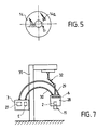
- Figure 5 is a plan view of a double-sided adhesive washer.
- Figure 6 is a schematic section of the skin.
- FIG 7 is a simplified diagram of a variant of the apparatus.
- FIG. 1 one can see an apparatus A allowing the microscopic structure of the skin to be observed in vivo.
- the device A is used to observe an area of the skin P of the arm B of a patient.
- the apparatus A comprises a confocal microscope 1, for example of the TSM TRACOR type for observation in real time.
- This microscope 1 is provided with an oil immersion objective 2, the magnification of which is advantageously equal to 50 and the numerical aperture equal to 0.85.
- the front distance of objective 2 (that is to say the distance between its exit face and the focal point) is at least equal to 200 micrometers.
- the area to be observed is illuminated by a source 3 of white light, constituted for example by a mercury lamp, filtered in the 400-700 nm band.
- the light beam passes through an inverting system 4 and is returned by a set 5 of mirrors, or equivalent means, along the optical axis of the objective 2.
- the beam of light coming from the source 3 is chopped by a disc 6 comprising a multitude of holes 7 of reduced diameter, (see Figure 2), judiciously distributed.
- the disc 6 is rotated about an axis perpendicular to its plane and parallel to the axis of the chopped light beam.
- Disc 6 is known as the Nipkow disc.
- the light returned by the area to be observed is focused on a receiving surface 8 with high sensitivity, in particular constituted by the receiving surface of an intensified camera E for example of the DAGE MTI SIT 68 type, sensitive up to 10 -5 lux.
- the light returned by the area to be observed is directed, towards the sensitive surface 8, by a semi-transparent mirror 9, or equivalent, and by a set of reflective surfaces 10.
- the returned beam, before reaching the surface 8, passes through holes 7 in disc 6.
- the traces of the light beams on the disc 6 are shown diagrammatically by circles t .
- the apparatus A comprises a contact tip 11 schematically represented in FIG. 1 and shown in more detail in FIG. 3, constituted by a sort of sleeve comprising a bottom 12 provided with a circular central opening 13 with a diameter at least equal to and preferably greater than the exit diameter of the objective 2.
- This objective at least through its lower part, is engaged in the end piece 11.
- the contact tip 11 is intended to bear by the lower flat face of its bottom 12 against the skin P and to be bonded to the skin in the annular region surrounding the opening 13.
- connection between the nozzle 11 and the skin is advantageously carried out using a double-sided adhesive washer 14 which has, in its center, a hole 14 has a diameter at least equal to that of the opening 13 .
- the assembly is mounted in such a way that a micrometric axial relative movement is possible between the contact end piece 11 and the objective 2.
- the objective 2 is carried by a fixed cross member 15, itself carried by a frame not shown.
- the contact plate 11 is carried by an arm 16, parallel to the cross bar 15 and slidably mounted along a direction parallel to the axis of the lens 2, by means of a guide 15 fixed on the cross member 15.
- the micrometric displacements of the arm 16, and therefore of the contact tip 11, relative to the cross member 15 are provided by a precision micrometer 17, carried by the cross member 15, with vernier to the micrometer.
- the relative movements between the contact tip 11 and the objective 2 are advantageously controlled by a stepping motor 18 and a control module 19. This arrangement makes it possible to measure the depths reached with an accuracy of 1 micrometer.
- the displays of the observation depths, corresponding to the relative displacements of the contact tip 11 and of the objective 2 can be displayed on a control screen 20.
- Fixing the contact plate 11 in the arm 16 is carried removably by screwing an external thread 11 provided on the end piece 11, a female thread 16a of the arm 16. It is thus possible to change the tip 11 and choose it according to the objective and the site to be observed.
- the micrometric displacements of the contact tip 11 relative to the objective 2 make it possible to vary the depth of the images, constituting horizontal sections of the skin, provided by the objective 2 This depth can reach 150 micrometers and the possible displacements of the nozzle 11 are therefore of an amplitude at least equal to 150 micrometers.
- a drop 21 of a liquid whose refractive index is substantially equal to that of the stratum cornea (surface layer of the skin) is provided between the exit face of the lens 2 and the skin to suppress interfaces and reflections of the skin surface.
- the drop 21 is a drop of oil with an immersion of refractive index equal to 1.5, while the refractive index of the stratum corneum is approximately 1.5.
- a capillary channel 22 is provided in the end piece 11 and opens on the one hand into the opening 13 and on the other hand on the cylindrical peripheral surface of this end piece 11, below the arm 16.
- This capillary channel 22 makes it possible to replenish the opening 13 with immersion oil, for example using a syringe, to maintain the presence of a drop 21 throughout the observation phase.
- the adhesive washer 14 contributes to the maintenance of the meniscus of the drop of oil 21.
- the apparatus A comprises a gutter system G (see FIG. 1) for holding the limb, namely the arm B in the example considered.
- the gutter G can be articulated on a ball joint R to allow adjustment in a horizontal plane.
- the apparatus A can be moved vertically as a whole to bring the end piece 11 into contact with the skin.
- the apparatus according to the invention be mobile as much as possible, to allow all skin parts of the human body to be reached relatively easily.
- FIG. 7 of the drawings schematically illustrates an alternative embodiment intended to give the device great mobility.
- the light source 3 and the camera E remain fixed, in a sub-assembly or fixed part 27 formed for example by a housing fixed to a frame.
- the other elements of the apparatus A shown in FIG. 1 form a sub-assembly or mobile part 28.
- the optical connection between the fixed part 27 and the mobile part 28 is ensured by two bundles 29, 30 of flexible optical fibers.
- the movable part 28 is therefore composed of the head of the microscope with the Nipkow disk 6, the objective 2, the contact tip 11 as well as the various optical elements 4, 5, 9 and 10 appearing in FIG. 1.
- the crew formed by the mobile part 28 is suspended from a fixed mast 31 by means of an arm 32 with ball joints, allowing the orientation of the mobile part 28 in all directions, and its movement to reach all the parts of the skin of the human body.
- the microscope head is illuminated by a 250 watt arc lamp, constituting the source 3, by means of the flexible optical fibers 29.
- the image is transmitted remotely to the camera E via an image conduit consisting of the bundle 30 of flexible optical fibers, with a length of about one meter.
- the moving element could only include the objective 2 and the contact system 11 and would therefore be lighter than in the variant mentioned above.
- the mobile equipment / microscope head link would be provided by optical fibers after correction of the trajectories. Again, the micrometric displacements would be communicated to the objective 2 while the end piece 11 would remain stationary during the observation.
- the image collected by the sensitive surface 8 can undergo processing, after recording on a tape. Denoising can be performed by real-time averaging. The elimination of the bands due to the spiral arrangement of the holes 7 of the disk of Nipkow 6 can be carried out by frequency analysis.
- Thickness measurements can give rise to field averaging in four virtual vertical cylinders with a diameter of 40 micrometers, the centers of which are located on a circle and angularly offset from each other by 90 °, so as to correct a possible inclination of the surface observed with respect to the optical axis of objective 2.
- a volume representation with registration of optical sections and transparency from 3D + and MIPS software can be performed (MISIS-St Etienne).
- the apparatus according to the invention makes it possible to carry out precise and quality observations of the skin in vivo over a depth of 150 micrometers which reaches, as illustrated in FIG. 6, the capillaries. It is therefore possible to make optical sections, in a non-invasive and non-destructive manner, through the stratum corneum SC, the epidermis EP (granular layer 22, spinous layer 23 and basal layer 24) and through the capillaries (terminal loops 25 and large handles 26).
- the average depths, expressed in micrometers, from the surface of the skin have been shown in Figure 6.
- the resolution is less than a micrometer and covers an observation field of 300 micrometers in diameter.
- the device works in real time which makes it possible to work in a 4D space (three dimensions + time).
- the contact tip 11 linked to the skin makes it possible to immobilize the field of observation by avoiding uncontrolled movements of the patient, following two directions X, Y, which contributes to obtaining good images.
- the tip 11, detachably attached to the arm 16 is interchangeable and its shape can be adapted to the anatomical site.
- connection between the underside of the bottom 12 of the nozzle and the skin makes it possible to limit the pressure of the contact on the skin and to eliminate the arterial beat. This connection makes it possible to maintain the meniscus of oil and to make exact thickness measurements.
Landscapes
- Health & Medical Sciences (AREA)
- Life Sciences & Earth Sciences (AREA)
- Physics & Mathematics (AREA)
- General Health & Medical Sciences (AREA)
- Surgery (AREA)
- Biomedical Technology (AREA)
- Molecular Biology (AREA)
- Veterinary Medicine (AREA)
- Public Health (AREA)
- Biophysics (AREA)
- Pathology (AREA)
- Engineering & Computer Science (AREA)
- Animal Behavior & Ethology (AREA)
- Heart & Thoracic Surgery (AREA)
- Medical Informatics (AREA)
- General Physics & Mathematics (AREA)
- Chemical & Material Sciences (AREA)
- Analytical Chemistry (AREA)
- Optics & Photonics (AREA)
- Radiology & Medical Imaging (AREA)
- Nuclear Medicine, Radiotherapy & Molecular Imaging (AREA)
- Dermatology (AREA)
- Ophthalmology & Optometry (AREA)
- Measurement Of The Respiration, Hearing Ability, Form, And Blood Characteristics Of Living Organisms (AREA)
- Measuring And Recording Apparatus For Diagnosis (AREA)
- Microscoopes, Condenser (AREA)
- Investigating Or Analysing Biological Materials (AREA)
Claims (10)
- Vorrichtung zur In-Vivo-Beobachtung der mikroskopischen Struktur der Haut oder eines ähnlichen Gewebes, bestehend aus einem konfokalen Mikroskop (1), das mit einer geeigneten Beleuchtung, mit einer allgemein unter dem Namen Nipkowscheibe bekannten rotierenden Scheibe (6), die mit Löchern mit kleinem Durchmesser versehen ist, mit einem Bildempfänger (8) mit hoher Empfindlichkeit und mit einem Immersionsobjektiv (2) ausgerüstet ist, dadurch gekennzeichnet, daß sie einen Kontaktaufsatz (11) aufweist, der dazu bestimmt ist, auf die Haut aufgesetzt zu werden, und in den zumindest der untere Teil des Mikroskops (2) eingesteckt ist, wobei der Aufsatz (11) eine zentrale Öffnung (13) aufweist und um die zentrale Öffnung herum mit der Haut verbunden ist sowie die Einheit derart montiert ist, daß eine axiale Relativbewegung zwischen dem Kontaktaufsatz (11) und dem Objektiv (2) möglich ist.
- Vorrichtung nach Anspruch 1, dadurch gekennzeichnet, daß der Kontaktaufsatz (11) mit der Haut durch eine zweiseitige Klebescheibe (14) verbunden ist, die ein mit der zentralen Öffnung (13) des Kontaktaufsatzes (11) übereinstimmendes zentrales Loch (14a) aufweist.
- Vorrichtung nach Anspruch 1 oder 2, dadurch gekennzeichnet, daß der Kontaktaufsatz (11) an einem Arm (16), insbesondere durch Verschrauben, lösbar befestigt ist.
- Vorrichtung nach einem der vorhergehenden Ansprüche, dadurch gekennzeichnet, daß das Objektiv (2) des konfokalen Mikroskops von einem feststehenden Halter (15) getragen ist, während der Kontaktaufsatz (11) relativ zum Objektiv verschiebbar montiert ist.
- Vorrichtung nach Anspruch 1 oder 2, dadurch gekennzeichnet, daß sie einen feststehenden Teil (27), der eine Lichtquelle (3) und eine Kamera (E) aufweist, und einen beweglichen Teil (28) umfaßt, der den Kopf des Mikroskops mit der Nipkowscheibe (6), dem Objektiv (2) und dem Kontaktaufsatz (11) aufweist, wobei die optische Verbindung zwischen dem feststehenden Teil (27) und dem beweglichen Teil (28) durch zwei Bündel (29, 30) von biegsamen optischen Fasern gewährleistet ist.
- Vorrichtung nach Anspruch 5, dadurch gekennzeichnet, daß der bewegliche Teil (28) über einen Arm (32) mit Kugelgelenken an einer feststehenden Stange (31) aufgehängt ist.
- Vorrichtung nach Anspruch 4 oder 5, dadurch gekennzeichnet, daß eine insbesondere durch einen elektrischen Schrittmotor (18) betätigte Mikrometerbewegungseinrichtung (17) zur Steuerung der Relativbewegungen zwischen dem Objektiv (2) und dem Kontaktaufsatz (11) vorgesehen ist.
- Vorrichtung nach Anspruch 1, dadurch gekennzeichnet, daß während der Beobachtung ein Tropfen (21) einer Flüssigkeit, deren Brechzahl im wesentlichen gleich der der obersten Schicht der Haut (Stratum corneum) ist, in der zentralen Öffnung (13) des Kontaktaufsatzes (11) angeordnet wird.
- Vorrichtung nach Anspruch 8, dadurch gekennzeichnet, daß die Flüssigkeit aus Immersionsöl besteht, dessen Brechzahl gleich 1,5 ist.
- Vorrichtung nach Anspruch 8 oder 9, dadurch gekennzeichnet, daß der Kontaktaufsatz (11) einen Kanal (22), insbesondere einen Kapillarkanal, aufweist, der die Nachversorgung der zentralen Öffnung (13) des Kontaktaufsatzes (11) mit Flüssigkeit gestattet.
Applications Claiming Priority (3)
| Application Number | Priority Date | Filing Date | Title |
|---|---|---|---|
| FR9112541A FR2682490B1 (fr) | 1991-10-11 | 1991-10-11 | Appareil pour observer in vivo la structure microscopique de la peau ou d'un tissu similaire. |
| FR9112541 | 1991-10-11 | ||
| PCT/FR1992/000924 WO1993007522A1 (fr) | 1991-10-11 | 1992-10-05 | Appareil pour observer in vivo la structure microscopique de la peau ou d'un tissu similaire |
Publications (2)
| Publication Number | Publication Date |
|---|---|
| EP0607295A1 EP0607295A1 (de) | 1994-07-27 |
| EP0607295B1 true EP0607295B1 (de) | 1997-04-09 |
Family
ID=9417820
Family Applications (1)
| Application Number | Title | Priority Date | Filing Date |
|---|---|---|---|
| EP92921712A Expired - Lifetime EP0607295B1 (de) | 1991-10-11 | 1992-10-05 | Vorrichtung für die in vivo beobachtung der mikroskopischen strukturen der haut oder eines ähnlichen gewebes |
Country Status (7)
| Country | Link |
|---|---|
| EP (1) | EP0607295B1 (de) |
| JP (2) | JPH06511406A (de) |
| CA (1) | CA2120034A1 (de) |
| DE (1) | DE69218957T2 (de) |
| ES (1) | ES2099835T3 (de) |
| FR (1) | FR2682490B1 (de) |
| WO (1) | WO1993007522A1 (de) |
Families Citing this family (17)
| Publication number | Priority date | Publication date | Assignee | Title |
|---|---|---|---|---|
| US5880880A (en) * | 1995-01-13 | 1999-03-09 | The General Hospital Corp. | Three-dimensional scanning confocal laser microscope |
| DE19654207A1 (de) | 1996-12-24 | 1998-06-25 | Leica Lasertechnik | TV-Kamera |
| US5978695A (en) * | 1997-08-18 | 1999-11-02 | Lucid Inc. | System for imaging mechanically stabilized tissue |
| NL1009296C2 (nl) * | 1998-06-02 | 1999-12-03 | Gerold Staudinger | Inrichting voor het optisch testen van objecten. |
| JP4504479B2 (ja) * | 1999-09-21 | 2010-07-14 | オリンパス株式会社 | 顕微鏡用液浸対物レンズ |
| JP2005128240A (ja) * | 2003-10-23 | 2005-05-19 | Olympus Corp | 対物レンズユニット及び顕微鏡並びに顕微鏡システム |
| JP2005301065A (ja) * | 2004-04-14 | 2005-10-27 | Olympus Corp | 観察装置 |
| JP4694139B2 (ja) * | 2004-04-01 | 2011-06-08 | オリンパス株式会社 | 顕微鏡 |
| JP4587693B2 (ja) * | 2004-04-07 | 2010-11-24 | オリンパス株式会社 | 生体観察装置 |
| DE602005004332T2 (de) | 2004-06-17 | 2009-01-08 | Cadent Ltd. | Verfahren zum Bereitstellen von Daten im Zusammenhang mit der Mundhöhle |
| CA2721271C (en) | 2008-04-09 | 2017-12-12 | Julian Itzcovitz | A medical system comprising a percutaneous probe |
| JP5712573B2 (ja) * | 2010-11-26 | 2015-05-07 | 花王株式会社 | 血流画像の形成方法 |
| JP6504914B2 (ja) * | 2015-05-20 | 2019-04-24 | 花王株式会社 | 皮膚毛細血管の観察方法 |
| JP6504913B2 (ja) * | 2015-05-20 | 2019-04-24 | 花王株式会社 | 皮膚毛細血管の観察方法 |
| JP6688164B2 (ja) * | 2016-06-09 | 2020-04-28 | 花王株式会社 | 皮膚毛細血管の観察方法 |
| FR3093635B1 (fr) * | 2019-03-14 | 2022-04-08 | Univ Bordeaux | Dispositif d’examen d’une zone capillaire |
| TWI778808B (zh) * | 2021-09-24 | 2022-09-21 | 國立臺灣大學 | 影像鏡頭的保護組件及影像器材組 |
Family Cites Families (2)
| Publication number | Priority date | Publication date | Assignee | Title |
|---|---|---|---|---|
| JP2512299B2 (ja) * | 1986-12-16 | 1996-07-03 | 株式会社 ハイロックス | 照明装置付き近接撮影用レンズ |
| CA2009129C (en) * | 1989-02-04 | 1995-02-14 | Mitsubishi Chemical Corporation | Image pickup head for image pickup device |
-
1991
- 1991-10-11 FR FR9112541A patent/FR2682490B1/fr not_active Expired - Fee Related
-
1992
- 1992-10-05 ES ES92921712T patent/ES2099835T3/es not_active Expired - Lifetime
- 1992-10-05 EP EP92921712A patent/EP0607295B1/de not_active Expired - Lifetime
- 1992-10-05 DE DE69218957T patent/DE69218957T2/de not_active Expired - Fee Related
- 1992-10-05 JP JP5506667A patent/JPH06511406A/ja active Pending
- 1992-10-05 WO PCT/FR1992/000924 patent/WO1993007522A1/fr not_active Ceased
- 1992-10-05 CA CA 2120034 patent/CA2120034A1/fr not_active Abandoned
-
2001
- 2001-08-17 JP JP2001248425A patent/JP2002148518A/ja active Pending
Also Published As
| Publication number | Publication date |
|---|---|
| WO1993007522A1 (fr) | 1993-04-15 |
| DE69218957T2 (de) | 1997-07-17 |
| CA2120034A1 (fr) | 1993-04-15 |
| JP2002148518A (ja) | 2002-05-22 |
| DE69218957D1 (de) | 1997-05-15 |
| FR2682490B1 (fr) | 1993-12-17 |
| EP0607295A1 (de) | 1994-07-27 |
| FR2682490A1 (fr) | 1993-04-16 |
| ES2099835T3 (es) | 1997-06-01 |
| JPH06511406A (ja) | 1994-12-22 |
Similar Documents
| Publication | Publication Date | Title |
|---|---|---|
| EP0607295B1 (de) | Vorrichtung für die in vivo beobachtung der mikroskopischen strukturen der haut oder eines ähnlichen gewebes | |
| US5719700A (en) | Apparatus for in vivo observation of the microscopic structure of the skin or of a similar tissue | |
| US7616986B2 (en) | Optical fiber scanner for performing multimodal optical imaging | |
| CA2344165C (fr) | Dispositif d'observation de l'interieur d'un corps produisant une qualite d'observation perfectionnee | |
| EP4185914B1 (de) | Systeme und verfahren zur durchführung einer mikroskopischen analyse einer probe | |
| JP5140396B2 (ja) | 光コネクタおよびこれを用いる光断層画像化装置 | |
| US6441356B1 (en) | Fiber-coupled, high-speed, angled-dual-axis optical coherence scanning microscopes | |
| EP1512939A1 (de) | Verfahren zum erhalten des bildes eines objekts, einrichtung zur ausführung des verfahrens und einrichtung zum abliefern von optischer strahlung mit niedriger kohärenz | |
| CN101884524B (zh) | 基于自适应光学技术的宽视场光学相干层析仪 | |
| WO2004073501A2 (en) | Optical coherence tomography with 3d coherence scanning | |
| US8184365B2 (en) | Optical instruments having dynamic focus | |
| FR2791548A1 (fr) | Dispositif d'observation d'un corps a haute resolution | |
| EP1789832A1 (de) | Transmissive scanning-verzögerungsleitung für oct | |
| EP1703837B1 (de) | Integrierter optischer miniaturisierter abtastkopf zur erzeugung eines homogenen konfokalen bilds und diesen verwendendes konfokales abbildungssystem | |
| US8593644B2 (en) | White light optical profilometer for measuring complex surfaces | |
| US20070070328A1 (en) | Method of determining a property of a fluid and spectroscopic system | |
| FR2852394A1 (fr) | Procede et appareillage d'imagerie de fluorescence fibree haute resolution | |
| US20250152002A1 (en) | Device for measuring the characteristics of the human eye using oct technology | |
| AU2022214125B2 (en) | Devices for ex vivo microscopic analysis of samples and in vivo microscopic analysis of the skin | |
| RU2458337C2 (ru) | Способ определения малых немагнитных включений и устройство для его осуществления | |
| CN107242850A (zh) | 一种三向协同扫描光学相干层析成像手持探头 | |
| FR2685789A1 (fr) | Microscope en champ proche fonctionnant par detection tunnel optique. | |
| KR20070082311A (ko) | Mems 기술을 이용한 광학 생체 진단기기의 프로브 | |
| George et al. | Confocal device and application strategies for endoluminal optical coherence microscopy | |
| Rolland et al. | Developments in optical coherence microscopy |
Legal Events
| Date | Code | Title | Description |
|---|---|---|---|
| PUAI | Public reference made under article 153(3) epc to a published international application that has entered the european phase |
Free format text: ORIGINAL CODE: 0009012 |
|
| 17P | Request for examination filed |
Effective date: 19940124 |
|
| AK | Designated contracting states |
Kind code of ref document: A1 Designated state(s): DE ES FR GB IT |
|
| GRAG | Despatch of communication of intention to grant |
Free format text: ORIGINAL CODE: EPIDOS AGRA |
|
| 17Q | First examination report despatched |
Effective date: 19960712 |
|
| GRAH | Despatch of communication of intention to grant a patent |
Free format text: ORIGINAL CODE: EPIDOS IGRA |
|
| GRAH | Despatch of communication of intention to grant a patent |
Free format text: ORIGINAL CODE: EPIDOS IGRA |
|
| GRAA | (expected) grant |
Free format text: ORIGINAL CODE: 0009210 |
|
| AK | Designated contracting states |
Kind code of ref document: B1 Designated state(s): DE ES FR GB IT |
|
| ITF | It: translation for a ep patent filed | ||
| GBT | Gb: translation of ep patent filed (gb section 77(6)(a)/1977) |
Effective date: 19970410 |
|
| REF | Corresponds to: |
Ref document number: 69218957 Country of ref document: DE Date of ref document: 19970515 |
|
| REG | Reference to a national code |
Ref country code: ES Ref legal event code: FG2A Ref document number: 2099835 Country of ref document: ES Kind code of ref document: T3 |
|
| PLBE | No opposition filed within time limit |
Free format text: ORIGINAL CODE: 0009261 |
|
| STAA | Information on the status of an ep patent application or granted ep patent |
Free format text: STATUS: NO OPPOSITION FILED WITHIN TIME LIMIT |
|
| 26N | No opposition filed | ||
| PGFP | Annual fee paid to national office [announced via postgrant information from national office to epo] |
Ref country code: GB Payment date: 20011003 Year of fee payment: 10 |
|
| PGFP | Annual fee paid to national office [announced via postgrant information from national office to epo] |
Ref country code: FR Payment date: 20011010 Year of fee payment: 10 |
|
| PGFP | Annual fee paid to national office [announced via postgrant information from national office to epo] |
Ref country code: DE Payment date: 20011022 Year of fee payment: 10 |
|
| PGFP | Annual fee paid to national office [announced via postgrant information from national office to epo] |
Ref country code: ES Payment date: 20011025 Year of fee payment: 10 |
|
| REG | Reference to a national code |
Ref country code: GB Ref legal event code: IF02 |
|
| PG25 | Lapsed in a contracting state [announced via postgrant information from national office to epo] |
Ref country code: GB Free format text: LAPSE BECAUSE OF NON-PAYMENT OF DUE FEES Effective date: 20021005 |
|
| PG25 | Lapsed in a contracting state [announced via postgrant information from national office to epo] |
Ref country code: ES Free format text: LAPSE BECAUSE OF NON-PAYMENT OF DUE FEES Effective date: 20021006 |
|
| PG25 | Lapsed in a contracting state [announced via postgrant information from national office to epo] |
Ref country code: DE Free format text: LAPSE BECAUSE OF NON-PAYMENT OF DUE FEES Effective date: 20030501 |
|
| GBPC | Gb: european patent ceased through non-payment of renewal fee |
Effective date: 20021005 |
|
| PG25 | Lapsed in a contracting state [announced via postgrant information from national office to epo] |
Ref country code: FR Free format text: LAPSE BECAUSE OF NON-PAYMENT OF DUE FEES Effective date: 20030630 |
|
| REG | Reference to a national code |
Ref country code: FR Ref legal event code: ST |
|
| REG | Reference to a national code |
Ref country code: ES Ref legal event code: FD2A Effective date: 20031112 |
|
| PG25 | Lapsed in a contracting state [announced via postgrant information from national office to epo] |
Ref country code: IT Free format text: LAPSE BECAUSE OF NON-PAYMENT OF DUE FEES Effective date: 20051005 |