EP0607564A2 - Procédé et dispositif pour éliminer des déchets sous forme de feuilles - Google Patents
Procédé et dispositif pour éliminer des déchets sous forme de feuilles Download PDFInfo
- Publication number
- EP0607564A2 EP0607564A2 EP93120002A EP93120002A EP0607564A2 EP 0607564 A2 EP0607564 A2 EP 0607564A2 EP 93120002 A EP93120002 A EP 93120002A EP 93120002 A EP93120002 A EP 93120002A EP 0607564 A2 EP0607564 A2 EP 0607564A2
- Authority
- EP
- European Patent Office
- Prior art keywords
- knives
- drive shaft
- container
- longitudinal
- fed
- Prior art date
- Legal status (The legal status is an assumption and is not a legal conclusion. Google has not performed a legal analysis and makes no representation as to the accuracy of the status listed.)
- Granted
Links
Images


Classifications
-
- B—PERFORMING OPERATIONS; TRANSPORTING
- B02—CRUSHING, PULVERISING, OR DISINTEGRATING; PREPARATORY TREATMENT OF GRAIN FOR MILLING
- B02C—CRUSHING, PULVERISING, OR DISINTEGRATING IN GENERAL; MILLING GRAIN
- B02C18/00—Disintegrating by knives or other cutting or tearing members which chop material into fragments
- B02C18/0007—Disintegrating by knives or other cutting or tearing members which chop material into fragments specially adapted for disintegrating documents
-
- F—MECHANICAL ENGINEERING; LIGHTING; HEATING; WEAPONS; BLASTING
- F23—COMBUSTION APPARATUS; COMBUSTION PROCESSES
- F23G—CREMATION FURNACES; CONSUMING WASTE PRODUCTS BY COMBUSTION
- F23G5/00—Incineration of waste; Incinerator constructions; Details, accessories or control therefor
- F23G5/02—Incineration of waste; Incinerator constructions; Details, accessories or control therefor with pretreatment
- F23G5/033—Incineration of waste; Incinerator constructions; Details, accessories or control therefor with pretreatment comminuting or crushing
-
- B—PERFORMING OPERATIONS; TRANSPORTING
- B02—CRUSHING, PULVERISING, OR DISINTEGRATING; PREPARATORY TREATMENT OF GRAIN FOR MILLING
- B02C—CRUSHING, PULVERISING, OR DISINTEGRATING IN GENERAL; MILLING GRAIN
- B02C18/00—Disintegrating by knives or other cutting or tearing members which chop material into fragments
- B02C18/06—Disintegrating by knives or other cutting or tearing members which chop material into fragments with rotating knives
- B02C18/16—Details
- B02C2018/166—Lubricating the knives of the cutting mechanisms
Definitions
- the invention relates to a method and an apparatus for the disposal of flat problem material.
- This is to be understood as material that cannot be easily reused and whose disposal causes problems.
- An example of this are lead frames that are left over after stamping out adhesive labels. These lead frames have coherent longitudinal and transverse webs. They consist of paper, cardboard, aluminum or plastic film, but are always coated with a self-adhesive material. So far, the lead frames, wound up in rolls, can only be brought to a landfill. Disposal at landfills is expensive and will only be possible to a limited extent for commercial waste of this type in the future.
- waste-to-energy plants need high-energy material to maintain a support fire during the night.
- the material is interesting for thermal recycling there because of its high energy content, but not in the form of poorly flammable, solidly bonded rolls.
- the object of the invention is therefore to provide a method and a device which convert problem material in such a way that it can be readily used for thermal recycling, in particular in a waste-to-energy plant.
- the handling of the material at the point of origin should be automated.
- leadframes and their parts usually get caught in processing machines.
- the present invention is intended to solve the problems described above.
- the width of the longitudinal strips can be selected so that subsequent transport by air flow in a tube is possible.
- the resulting granulate can be transported automatically in a central disposal system and can also be sent to a waste incineration plant, since its surface / space ratio is particularly high, in contrast to glued rolls of lead frames, where the flames have practically no access to the interior.
- the large numerical ratio mentioned is therefore an essential prerequisite for combustion without the addition of further fuels.
- the remaining longitudinal strips are conveyed, preferably by an air stream, through a tube from the slitter to the cross cutter.
- the width of the longitudinal strips can be selected so that when they are subsequently transported in a tube, cross webs remaining due to air flow get caught on at least one longitudinal web.
- a device for carrying out the method contains, in addition to knives for the longitudinal and transverse cutting, above all an application station which serves to dispense the lubricant, in particular oil.
- the granules can be fed to a press container, again from an air stream, by means of further pipes, whereby the transport volume is reduced.
- FIG. 1 shows two printing presses 2, which print labels within a web running from a roll and punch out the labels. A then remaining lead frame 4 of z. B. 50 cm width is subtracted upwards. Three labels were printed next to each other, so that the lead frame has three approximately rectangular openings next to each other.
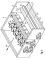
- the leadframe consists of four longitudinal bars (perpendicular) and cross bars arranged at right angles to them. The lead frames 4 are each fed to a slitter 6, as shown in perspective in FIG. 2.
- the slitter has cooperating pairs of conveyor rollers 8, which pull the lead frame in the direction of arrow 10, past an application station 12, which applies a lubricant, in particular oil, to the lower side of the lead frame without contact.
- the application station has a flat storage container 12.1 below, which holds the liquid lubricant 12.2.
- a freely rotatably mounted metering roller 12.3 is partially immersed in the lubricant, takes along lubricant on its surface during its rotation and transfers it to a roller provided with radial, elastic bristles (brush roller 12.5). The brush roller is driven in the direction of an arrow 12.6.
- a scraper 12.7 which runs over its entire length and which projects so close to the brush roller that the bristles are bent as the brush roller rotates and then snap back upwards. Doing so the lubricant adhering to the bristles is thrown in fine droplets against the lower surface of a lead frame drawn over it. The lubricant is therefore applied without contact between the bristles and the lead frame.
- the lubricant may be easier to apply, such as spraying or rolling.
- the lead frames are pushed into pairs of interacting, rotating cutter disks 14 by the conveyor rollers 8.
- An air flow guided in the running direction of the lead frame acts as a support.
- the cutter disks 14 can be moved and locked in the direction of their drive shaft. They are set so that they cut through the crossbars of the lead frames. If you do not want individual crossbar pieces, only one pair of knife disks can be effective between two longitudinal webs.
- FIGS. 3 and 4 show the cross cutter in two mutually perpendicular cuts, both in the longitudinal direction of a tube 26 containing the cross cutter.
- the cross cutter has three knives 28 which are arranged at the same angles and are connected in a rotationally fixed manner to a drive shaft 30 via circular disks 29.
- the cutting edges of the knives are at an angle to the axis and are curved slightly outwards so that they lie within an imaginary cylinder surface.
- the longitudinal strips are sucked in the direction of the arrows 32 into the area of the knives 28. 3 and 4, the strips are cut into pieces by an axially parallel cutting edge 34 (FIG. 4).
- Passage openings 36 for the conveying air remain between the knives and the drive shaft 30. Further passage openings for the conveying air exist between those knives 28 that are not currently involved in the cutting process and the inner wall of the tube 26.
- granulate is formed which is sucked in by the blower 22 through a pipe 40 (FIG. 1), passes through the blower and then via a cyclone 42 for air separation, a climate lock 44 from a further blower 46 through a pipe 48 is finally fed to a press 52 via a collecting container 50. This presses the granules into a press container 54, which is then fed to a disposal point, in particular a waste-to-energy plant.
Landscapes
- Engineering & Computer Science (AREA)
- Mechanical Engineering (AREA)
- General Engineering & Computer Science (AREA)
- Food Science & Technology (AREA)
- Details Of Cutting Devices (AREA)
- Processing Of Solid Wastes (AREA)
- Ropes Or Cables (AREA)
- Processing And Handling Of Plastics And Other Materials For Molding In General (AREA)
- Auxiliary Devices For And Details Of Packaging Control (AREA)
- Dry Formation Of Fiberboard And The Like (AREA)
- Diaphragms For Electromechanical Transducers (AREA)
Applications Claiming Priority (2)
| Application Number | Priority Date | Filing Date | Title |
|---|---|---|---|
| DE4301492A DE4301492A1 (de) | 1993-01-21 | 1993-01-21 | Verfahren und Vorrichtung zum Entsorgen von flächenhaftem Problemmaterial |
| DE4301492 | 1993-01-21 |
Publications (3)
| Publication Number | Publication Date |
|---|---|
| EP0607564A2 true EP0607564A2 (fr) | 1994-07-27 |
| EP0607564A3 EP0607564A3 (fr) | 1995-01-18 |
| EP0607564B1 EP0607564B1 (fr) | 1998-03-25 |
Family
ID=6478608
Family Applications (1)
| Application Number | Title | Priority Date | Filing Date |
|---|---|---|---|
| EP93120002A Expired - Lifetime EP0607564B1 (fr) | 1993-01-21 | 1993-12-10 | Procédé et dispositif pour éliminer des déchets sous forme de feuilles |
Country Status (5)
| Country | Link |
|---|---|
| EP (1) | EP0607564B1 (fr) |
| AT (1) | ATE164329T1 (fr) |
| DE (2) | DE4301492A1 (fr) |
| DK (1) | DK0607564T3 (fr) |
| ES (1) | ES2117087T3 (fr) |
Cited By (3)
| Publication number | Priority date | Publication date | Assignee | Title |
|---|---|---|---|---|
| EP1574258A1 (fr) * | 2004-03-09 | 2005-09-14 | Kabushiki Kaisha Toshiba | Déchiqueteur de feuille de papier |
| WO2008046956A1 (fr) | 2006-10-19 | 2008-04-24 | Upm-Kymmene Oyj | Procédé et dispositif de production de matériau composite à base de bois |
| CN108262519A (zh) * | 2018-01-31 | 2018-07-10 | 朱承启 | 一种基于物联网的用于工业生产的智能切割设备 |
Family Cites Families (14)
| Publication number | Priority date | Publication date | Assignee | Title |
|---|---|---|---|---|
| US3453976A (en) * | 1967-01-30 | 1969-07-08 | Gen Incinerators Of California | Method and apparatus for destroying bulk paper and other bulk materials |
| SE308062B (fr) * | 1968-04-02 | 1969-01-27 | Oerebro Ab | |
| DE2128106C3 (de) * | 1971-06-05 | 1981-04-02 | Lindemann Maschinenfabrik GmbH, 4000 Düsseldorf | Vorrichtung zum Zerkleinern von Altpapier |
| US3894697A (en) * | 1974-04-19 | 1975-07-15 | Pitney Bowes Inc | Paper shredder |
| FR2327819A2 (fr) * | 1975-10-14 | 1977-05-13 | Maillet Edgard | Dechiqueteur pour le conditionnement des ferrailles d'epaisseur au plus egale a 5 mm |
| DE2605226A1 (de) * | 1976-02-11 | 1977-08-18 | Bernhard Laufenberg Maschinen | Aktenvernichtungsmaschine, insbesondere zum vernichten von mikrofilmen |
| JPS53137486A (en) * | 1977-05-06 | 1978-11-30 | Takeshi Hatanaka | Document shredder |
| DE3001230C2 (de) * | 1980-01-15 | 1981-12-17 | Sundwiger Eisenhütte Maschinenfabrik Grah & Co, 5870 Hemer | Verfahren zum Spalten eines Bandes und Spaltanlage für Bänder |
| DE3137844C2 (de) * | 1981-09-23 | 1984-04-05 | Messerschmitt-Bölkow-Blohm GmbH, 8000 München | Verfahren zum Herstellen von Kurzfasern |
| DE3448516C2 (de) * | 1984-04-03 | 1998-02-12 | Schleicher & Co Int | Ballenpresse zum Zusammenpressen von Materialien wie Papierabfällen o. dgl. zu Ballen |
| DE3612431A1 (de) * | 1986-04-12 | 1987-10-15 | Bernhard Laufenberg | Vorrichtung zum zerkleinern von papier-, film- und kunststoffblaettern oder -streifen |
| US5016828A (en) * | 1988-08-12 | 1991-05-21 | Sharp Kabushiki Kaisha | Shredding machine |
| DE3900874A1 (de) * | 1989-01-13 | 1990-07-26 | Hauni Werke Koerber & Co Kg | Fuellstoff fuer nachgiebige behaelter mit flexiblem umhuellungsmaterial und vorrichtung zum herstellen eines derartigen fuellstoffs |
| DE4005271C1 (fr) * | 1990-02-20 | 1991-10-02 | Reinhardt Maschinenbau Gmbh, 7032 Sindelfingen, De |
-
1993
- 1993-01-21 DE DE4301492A patent/DE4301492A1/de not_active Withdrawn
- 1993-12-10 AT AT93120002T patent/ATE164329T1/de not_active IP Right Cessation
- 1993-12-10 EP EP93120002A patent/EP0607564B1/fr not_active Expired - Lifetime
- 1993-12-10 ES ES93120002T patent/ES2117087T3/es not_active Expired - Lifetime
- 1993-12-10 DE DE59308309T patent/DE59308309D1/de not_active Expired - Fee Related
- 1993-12-10 DK DK93120002T patent/DK0607564T3/da active
Cited By (8)
| Publication number | Priority date | Publication date | Assignee | Title |
|---|---|---|---|---|
| EP1574258A1 (fr) * | 2004-03-09 | 2005-09-14 | Kabushiki Kaisha Toshiba | Déchiqueteur de feuille de papier |
| US7198212B2 (en) | 2004-03-09 | 2007-04-03 | Kabushiki Kaisha Toshiba | Sheet shredder |
| CN100352552C (zh) * | 2004-03-09 | 2007-12-05 | 株式会社东芝 | 薄片切碎机 |
| WO2008046956A1 (fr) | 2006-10-19 | 2008-04-24 | Upm-Kymmene Oyj | Procédé et dispositif de production de matériau composite à base de bois |
| RU2447943C2 (ru) * | 2006-10-19 | 2012-04-20 | ЮПМ-Кюммене Оюй | Способ и установка для получения древесного композиционного материала |
| CN101522309B (zh) * | 2006-10-19 | 2013-04-03 | 芬欧汇川公司 | 生产木材复合材料的方法和设备 |
| US8474736B2 (en) | 2006-10-19 | 2013-07-02 | Upm-Kymmene Oyj | Method and device for producing chaff and wood composite material |
| CN108262519A (zh) * | 2018-01-31 | 2018-07-10 | 朱承启 | 一种基于物联网的用于工业生产的智能切割设备 |
Also Published As
| Publication number | Publication date |
|---|---|
| DE4301492A1 (de) | 1994-07-28 |
| EP0607564A3 (fr) | 1995-01-18 |
| EP0607564B1 (fr) | 1998-03-25 |
| DK0607564T3 (da) | 1999-01-11 |
| ATE164329T1 (de) | 1998-04-15 |
| DE59308309D1 (de) | 1998-04-30 |
| ES2117087T3 (es) | 1998-08-01 |
Similar Documents
| Publication | Publication Date | Title |
|---|---|---|
| DE60026399T2 (de) | Verfahren zur automatischen Herstellung von Beuteln mit Löchern | |
| DE3343805A1 (de) | Verfahren und vorrichtung zum einwickeln von behaeltern und aehnlichem | |
| DE2007689A1 (de) | Schneidegerät für blattförmiges Material | |
| EP1185398B1 (fr) | Unite d'acheminement de feuille intercalaire pour une machine a decouper un produit | |
| EP0360108B1 (fr) | Procédé et dispositif pour la distribution d'étiquettes | |
| CH623289A5 (fr) | ||
| DE3100812A1 (de) | Verbesserte umlauf-plattenschneidvorrichtungen, insbesondere zum schneiden von holzfurnieren | |
| DE2902315C2 (de) | Vorrichtung zum Etikettieren von Behältern | |
| DE69829305T2 (de) | Aufbringstation für klebstoffe und etikettiermaschine | |
| DE2708644A1 (de) | Verfahren und vorrichtung zum verspleissen von blatt- oder bahnfoermigem material | |
| DE202015105416U1 (de) | Rotierende Schneid- und/oder Perforiervorrichtung für flächiges Endlosmaterial | |
| DE4338561A1 (de) | Vorrichtung zur Vorbereitung/Vorbehandlung verpreßbarer Hohlkörper für Recycling | |
| EP0655389B1 (fr) | Procédé et appareil pour emballer un rouleau de matériau en bande | |
| EP0607564B1 (fr) | Procédé et dispositif pour éliminer des déchets sous forme de feuilles | |
| DE102019117180A1 (de) | Vorrichtung und Verfahren zum Verbinden von zwei jeweils von einer Bobine ablaufenden Materialbahnen | |
| DE9217023U1 (de) | Verpackungsbeutel aus Papier oder Kunststoff | |
| DE2140109A1 (de) | Verfahren und Vorrichtung zum Abpacken gefalteter Bahnabschnitte | |
| EP0636543B1 (fr) | Procédé et dispositif pour la manipulation de l'habillage utilisé d'un rouleau de matériau en bande | |
| DE10243959B4 (de) | Vorrichtung zur Herstellung von Folienbahnen aus einem Folienschlauch | |
| DE3037166C2 (de) | Verfahren zum Schneiden von Kartonzuschnitten sowie Steuerschaltung zur Durchführung des Verfahrens | |
| EP1542859B1 (fr) | Procede de mise a disposition de feuilles en continu | |
| EP2322292B1 (fr) | Dispositif et procédé d'enlèvement d'étiquettes d'objets | |
| DE2430515A1 (de) | Drehbare schneidvorrichtung fuer wellpappe | |
| DE2365807A1 (de) | Vorrichtung zum verbinden von bahnen selbsthaftenden etikettenmaterials | |
| DE3524305A1 (de) | Einzugsvorrichtung |
Legal Events
| Date | Code | Title | Description |
|---|---|---|---|
| PUAI | Public reference made under article 153(3) epc to a published international application that has entered the european phase |
Free format text: ORIGINAL CODE: 0009012 |
|
| AK | Designated contracting states |
Kind code of ref document: A2 Designated state(s): AT BE CH DE DK ES FR GB IT LI NL SE |
|
| PUAL | Search report despatched |
Free format text: ORIGINAL CODE: 0009013 |
|
| AK | Designated contracting states |
Kind code of ref document: A3 Designated state(s): AT BE CH DE DK ES FR GB IT LI NL SE |
|
| 17P | Request for examination filed |
Effective date: 19950602 |
|
| 17Q | First examination report despatched |
Effective date: 19970128 |
|
| GRAG | Despatch of communication of intention to grant |
Free format text: ORIGINAL CODE: EPIDOS AGRA |
|
| GRAG | Despatch of communication of intention to grant |
Free format text: ORIGINAL CODE: EPIDOS AGRA |
|
| GRAH | Despatch of communication of intention to grant a patent |
Free format text: ORIGINAL CODE: EPIDOS IGRA |
|
| GRAH | Despatch of communication of intention to grant a patent |
Free format text: ORIGINAL CODE: EPIDOS IGRA |
|
| GRAA | (expected) grant |
Free format text: ORIGINAL CODE: 0009210 |
|
| AK | Designated contracting states |
Kind code of ref document: B1 Designated state(s): AT BE CH DE DK ES FR GB IT LI NL SE |
|
| REF | Corresponds to: |
Ref document number: 164329 Country of ref document: AT Date of ref document: 19980415 Kind code of ref document: T |
|
| REG | Reference to a national code |
Ref country code: CH Ref legal event code: EP |
|
| REF | Corresponds to: |
Ref document number: 59308309 Country of ref document: DE Date of ref document: 19980430 |
|
| ITF | It: translation for a ep patent filed | ||
| GBT | Gb: translation of ep patent filed (gb section 77(6)(a)/1977) |
Effective date: 19980611 |
|
| REG | Reference to a national code |
Ref country code: CH Ref legal event code: NV Representative=s name: PATENTANWAELTE SCHAAD, BALASS, MENZL & PARTNER AG |
|
| ET | Fr: translation filed | ||
| REG | Reference to a national code |
Ref country code: ES Ref legal event code: FG2A Ref document number: 2117087 Country of ref document: ES Kind code of ref document: T3 |
|
| PGFP | Annual fee paid to national office [announced via postgrant information from national office to epo] |
Ref country code: ES Payment date: 19981221 Year of fee payment: 6 |
|
| PGFP | Annual fee paid to national office [announced via postgrant information from national office to epo] |
Ref country code: SE Payment date: 19981222 Year of fee payment: 6 Ref country code: BE Payment date: 19981222 Year of fee payment: 6 Ref country code: AT Payment date: 19981222 Year of fee payment: 6 |
|
| PGFP | Annual fee paid to national office [announced via postgrant information from national office to epo] |
Ref country code: CH Payment date: 19981229 Year of fee payment: 6 |
|
| PGFP | Annual fee paid to national office [announced via postgrant information from national office to epo] |
Ref country code: NL Payment date: 19981231 Year of fee payment: 6 |
|
| REG | Reference to a national code |
Ref country code: DK Ref legal event code: T3 |
|
| PLBE | No opposition filed within time limit |
Free format text: ORIGINAL CODE: 0009261 |
|
| STAA | Information on the status of an ep patent application or granted ep patent |
Free format text: STATUS: NO OPPOSITION FILED WITHIN TIME LIMIT |
|
| 26N | No opposition filed | ||
| PGFP | Annual fee paid to national office [announced via postgrant information from national office to epo] |
Ref country code: GB Payment date: 19991202 Year of fee payment: 7 |
|
| PG25 | Lapsed in a contracting state [announced via postgrant information from national office to epo] |
Ref country code: AT Free format text: LAPSE BECAUSE OF NON-PAYMENT OF DUE FEES Effective date: 19991210 |
|
| PG25 | Lapsed in a contracting state [announced via postgrant information from national office to epo] |
Ref country code: SE Free format text: LAPSE BECAUSE OF NON-PAYMENT OF DUE FEES Effective date: 19991211 |
|
| PGFP | Annual fee paid to national office [announced via postgrant information from national office to epo] |
Ref country code: DE Payment date: 19991217 Year of fee payment: 7 Ref country code: FR Payment date: 19991217 Year of fee payment: 7 |
|
| PGFP | Annual fee paid to national office [announced via postgrant information from national office to epo] |
Ref country code: DK Payment date: 19991222 Year of fee payment: 7 |
|
| PG25 | Lapsed in a contracting state [announced via postgrant information from national office to epo] |
Ref country code: LI Free format text: LAPSE BECAUSE OF NON-PAYMENT OF DUE FEES Effective date: 19991231 Ref country code: CH Free format text: LAPSE BECAUSE OF NON-PAYMENT OF DUE FEES Effective date: 19991231 Ref country code: BE Free format text: LAPSE BECAUSE OF NON-PAYMENT OF DUE FEES Effective date: 19991231 |
|
| BERE | Be: lapsed |
Owner name: MATHO KONSTRUKTION & MASCHINENBAU G.M.B.H. Effective date: 19991231 |
|
| PG25 | Lapsed in a contracting state [announced via postgrant information from national office to epo] |
Ref country code: NL Free format text: LAPSE BECAUSE OF NON-PAYMENT OF DUE FEES Effective date: 20000701 |
|
| EUG | Se: european patent has lapsed |
Ref document number: 93120002.6 |
|
| NLV4 | Nl: lapsed or anulled due to non-payment of the annual fee |
Effective date: 20000701 |
|
| PG25 | Lapsed in a contracting state [announced via postgrant information from national office to epo] |
Ref country code: GB Free format text: LAPSE BECAUSE OF NON-PAYMENT OF DUE FEES Effective date: 20001210 Ref country code: DK Free format text: LAPSE BECAUSE OF NON-PAYMENT OF DUE FEES Effective date: 20001210 |
|
| PG25 | Lapsed in a contracting state [announced via postgrant information from national office to epo] |
Ref country code: ES Free format text: LAPSE BECAUSE OF NON-PAYMENT OF DUE FEES Effective date: 20001211 |
|
| GBPC | Gb: european patent ceased through non-payment of renewal fee |
Effective date: 20001210 |
|
| REG | Reference to a national code |
Ref country code: DK Ref legal event code: EBP |
|
| PG25 | Lapsed in a contracting state [announced via postgrant information from national office to epo] |
Ref country code: FR Free format text: LAPSE BECAUSE OF NON-PAYMENT OF DUE FEES Effective date: 20010831 |
|
| REG | Reference to a national code |
Ref country code: FR Ref legal event code: ST |
|
| PG25 | Lapsed in a contracting state [announced via postgrant information from national office to epo] |
Ref country code: DE Free format text: LAPSE BECAUSE OF NON-PAYMENT OF DUE FEES Effective date: 20011002 |
|
| REG | Reference to a national code |
Ref country code: ES Ref legal event code: FD2A Effective date: 20010113 |
|
| PG25 | Lapsed in a contracting state [announced via postgrant information from national office to epo] |
Ref country code: IT Free format text: LAPSE BECAUSE OF NON-PAYMENT OF DUE FEES;WARNING: LAPSES OF ITALIAN PATENTS WITH EFFECTIVE DATE BEFORE 2007 MAY HAVE OCCURRED AT ANY TIME BEFORE 2007. THE CORRECT EFFECTIVE DATE MAY BE DIFFERENT FROM THE ONE RECORDED. Effective date: 20051210 |