EP0607574A1 - Encrier - Google Patents
Encrier Download PDFInfo
- Publication number
- EP0607574A1 EP0607574A1 EP93120184A EP93120184A EP0607574A1 EP 0607574 A1 EP0607574 A1 EP 0607574A1 EP 93120184 A EP93120184 A EP 93120184A EP 93120184 A EP93120184 A EP 93120184A EP 0607574 A1 EP0607574 A1 EP 0607574A1
- Authority
- EP
- European Patent Office
- Prior art keywords
- frame
- channel
- transfer roller
- fountain assembly
- radial surface
- Prior art date
- Legal status (The legal status is an assumption and is not a legal conclusion. Google has not performed a legal analysis and makes no representation as to the accuracy of the status listed.)
- Granted
Links
- 239000012530 fluid Substances 0.000 claims abstract description 40
- 239000000203 mixture Substances 0.000 claims abstract description 24
- 238000005406 washing Methods 0.000 claims abstract description 24
- 239000004033 plastic Substances 0.000 claims abstract description 8
- 229920003023 plastic Polymers 0.000 claims abstract description 8
- 238000005507 spraying Methods 0.000 claims abstract description 4
- 239000000463 material Substances 0.000 claims description 19
- 230000001050 lubricating effect Effects 0.000 claims description 10
- 238000007789 sealing Methods 0.000 claims description 10
- 230000002745 absorbent Effects 0.000 claims description 8
- 239000002250 absorbent Substances 0.000 claims description 8
- 230000000295 complement effect Effects 0.000 claims description 8
- 239000002131 composite material Substances 0.000 claims description 7
- 238000005461 lubrication Methods 0.000 claims description 7
- 239000007921 spray Substances 0.000 claims description 7
- 239000006260 foam Substances 0.000 claims description 6
- 239000007788 liquid Substances 0.000 claims description 6
- 229920000642 polymer Polymers 0.000 claims description 6
- 239000004698 Polyethylene Substances 0.000 claims description 5
- -1 polyethylene Polymers 0.000 claims description 5
- 229920000573 polyethylene Polymers 0.000 claims description 5
- 230000003014 reinforcing effect Effects 0.000 claims description 4
- 229910052751 metal Inorganic materials 0.000 abstract description 6
- 239000002184 metal Substances 0.000 abstract description 6
- 239000000976 ink Substances 0.000 description 50
- 238000007774 anilox coating Methods 0.000 description 11
- 239000011248 coating agent Substances 0.000 description 8
- 239000000314 lubricant Substances 0.000 description 8
- XLYOFNOQVPJJNP-UHFFFAOYSA-N water Substances O XLYOFNOQVPJJNP-UHFFFAOYSA-N 0.000 description 8
- 230000000712 assembly Effects 0.000 description 7
- 238000000429 assembly Methods 0.000 description 7
- 238000000576 coating method Methods 0.000 description 7
- 238000007639 printing Methods 0.000 description 7
- 238000004140 cleaning Methods 0.000 description 5
- 239000000243 solution Substances 0.000 description 5
- 125000006850 spacer group Chemical group 0.000 description 5
- 238000003860 storage Methods 0.000 description 5
- 239000008199 coating composition Substances 0.000 description 4
- 230000007797 corrosion Effects 0.000 description 3
- 238000005260 corrosion Methods 0.000 description 3
- 230000000694 effects Effects 0.000 description 3
- 238000004519 manufacturing process Methods 0.000 description 3
- PXHVJJICTQNCMI-UHFFFAOYSA-N Nickel Chemical compound [Ni] PXHVJJICTQNCMI-UHFFFAOYSA-N 0.000 description 2
- 229910000831 Steel Inorganic materials 0.000 description 2
- 238000007667 floating Methods 0.000 description 2
- 238000000034 method Methods 0.000 description 2
- 239000010959 steel Substances 0.000 description 2
- 238000006467 substitution reaction Methods 0.000 description 2
- 239000002351 wastewater Substances 0.000 description 2
- 239000004809 Teflon Substances 0.000 description 1
- 229920006362 Teflon® Polymers 0.000 description 1
- 229910052782 aluminium Inorganic materials 0.000 description 1
- XAGFODPZIPBFFR-UHFFFAOYSA-N aluminium Chemical compound [Al] XAGFODPZIPBFFR-UHFFFAOYSA-N 0.000 description 1
- 238000010276 construction Methods 0.000 description 1
- 230000001276 controlling effect Effects 0.000 description 1
- 238000010790 dilution Methods 0.000 description 1
- 239000012895 dilution Substances 0.000 description 1
- 229920001971 elastomer Polymers 0.000 description 1
- 239000000806 elastomer Substances 0.000 description 1
- 239000006261 foam material Substances 0.000 description 1
- 229920001821 foam rubber Polymers 0.000 description 1
- 238000007756 gravure coating Methods 0.000 description 1
- 238000007646 gravure printing Methods 0.000 description 1
- 229920001903 high density polyethylene Polymers 0.000 description 1
- 239000004700 high-density polyethylene Substances 0.000 description 1
- 229910052759 nickel Inorganic materials 0.000 description 1
- 238000007645 offset printing Methods 0.000 description 1
- 230000002028 premature Effects 0.000 description 1
- 230000002265 prevention Effects 0.000 description 1
- 230000001105 regulatory effect Effects 0.000 description 1
- 239000007787 solid Substances 0.000 description 1
- 239000002904 solvent Substances 0.000 description 1
- 239000000126 substance Substances 0.000 description 1
- 239000000758 substrate Substances 0.000 description 1
Images




Classifications
-
- B—PERFORMING OPERATIONS; TRANSPORTING
- B41—PRINTING; LINING MACHINES; TYPEWRITERS; STAMPS
- B41F—PRINTING MACHINES OR PRESSES
- B41F31/00—Inking arrangements or devices
- B41F31/02—Ducts, containers, supply or metering devices
- B41F31/027—Ink rail devices for inking ink rollers
-
- B—PERFORMING OPERATIONS; TRANSPORTING
- B41—PRINTING; LINING MACHINES; TYPEWRITERS; STAMPS
- B41P—INDEXING SCHEME RELATING TO PRINTING, LINING MACHINES, TYPEWRITERS, AND TO STAMPS
- B41P2235/00—Cleaning
- B41P2235/10—Cleaning characterised by the methods or devices
- B41P2235/26—Spraying devices
Definitions
- the present invention relates to a fountain assembly for applying a fluid composition such as ink, uniformly to the circumferential surface of a rotating transfer roller, for example, in a flexographic printing apparatus.
- ink must be moved from a storage reservoir to a series of ink transfer rollers by means of an ink fountain.
- ink fountain In the technique of flexographic printing, it is known to apply colored inks to a web of a moving substrate, such as paper, with a rotating transfer or anilox roller, and to directly apply the ink uniformly and in a metered amount onto such a roller by means of an ink fountain assembly. From the roller, the ink is transferred to a plate cylinder and then to the material to be printed.
- Fountain assemblies generally include a channel extending the length of the transfer roller and in contact with the circumferential surface of it.
- a regulated amount of ink is continuously supplied to the fountain and then from the fountain to the roller with excess ink being returned from the fountain to an ink storage reservoir.
- a pair of doctor blades extend longitudinally on either side of the channel. The doctor blades are angled toward the transfer roller surface and serve both to seal the channel to the roller and to form an uniform film of the coating liquid on the roller transfer surface. As the roller rotates with respect to the fountain, microscopic cells engraved on the roller fill with ink. The doctor blades scrape excess ink from the roller and leave a uniform film of ink across the roller. The blades acts as an ink seal between the fountain body and the roller.
- the assembly also has some means to seal the channel at its ends so that the ink does not escape from the sides of the fountain assembly. This type of coating system is particularly used in flexographic and gravure printing, and coating applicators in a variety of industrial processes.
- U.S. patents 4,026,210 and 5,027,513 disclose a printing apparatus having a doctor blade made from steel and teflon polymer.
- U.S. patents 4,821,672; 5,125,341 and 4,590,855 disclose the various types of end seals useful in fountain assemblies.
- U.S. patent 5,003,877 discloses an inker having dams that confine ink to a specific area of the rollers and water is used as a lubricating fluid.
- U.S. patent 3,186,339 shows an apparatus where fluid under pressure is used to move a number of plungers which cause a doctor blade to be pressed against a roller.
- patent 4,463,675 shows an apparatus which uses fluid pressure applied to a number of cylinders to press a blade against a roller.
- U.S. patents 4,906,335 and 4,789,432 teach fluid pressure application means that is actuated to press a blade against a roller and liquid filled tubes are used to effect angular adjustment.
- U.S. patent 4,461,211 shows fluid pressure means to press an inking assembly including blades against a roller.
- U.S. patent 5,003,877 discloses a pumped ink supply and a water wash that cleans the inker. Wash fluid is conducted through the ink supply lines rather than through nozzles in the doctor blade assembly.
- U.S. patents 5,085,144 and 5,058,502 show supplying ink to fountains.
- patent 5,040,457 discloses spray nozzle assemblies with press dampeners for use during offset printing, but which are not used to clean fountain assemblies.
- U.S. patent 4,796,528 shows an ink fountain with zone separators to permit use of different inks simultaneously.
- doctor blade control An important factor for effective doctoring is to maintain doctor blade control. That is to keep the blades at a uniform blade angle and pressure along their entire length at a contact line with the rotating transfer cylinder. If the blade angle is incorrect, wiping action, and thus printing will be poor. Excessive blade loading pressure will also accelerate wear of both the blade and the roller surface and increase friction which will cause premature roller wear.
- the fountain assembly has considerable mass since it is manufactured from a block of metal, usually cast aluminum with an electroless nickel coating for corrosion resistance. In one aspect of the present invention, this problem is solved by producing a fountain assembly which is composed of light weight, polymeric, plastic materials which are much easier to control than solid metal assemblies.
- the weight of the fountain of the present invention typically has only one-third of the weight of prior art fountains.
- lightness of weight of assembly material has the disadvantage of loss of rigidity of the blade assembly. This produces a deflection of the fountain thus causing the blades to have a tendency to be uneven across the length of the roller surface.
- This flexibility problem is solved without sacrificing lightness of weight by providing a fountain with a rigid metal backbone.
- An important additional feature of the invention is that the fountain assembly can be adjusted by hand without the use of separate tools.
- Prior art fountains are complex to adjust, and hence industrial establishments are induced to have spare fountains on hand for substitution onto coating machines. In effect, the spare fountains are adjusted off the coating machine and then subsequently attached to the coater.
- the tool-less fountain of this invention is adjustable by hand without separate tools. This allows quick make-ready of the fountain by simple adjustment while it is still attached to the coating machine. Production time loss is thus minimized.
- the resulting fountain assembly is light weight, rigid, corrosion resistant, and easily cleaned and maintained without the use of tools.
- the invention provides an improved fountain assembly whose additional improved features are discussed hereinafter.
- Figure 1 is a side elevational view of the fountain assembly of the invention and shows its use with an anilox roller.
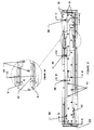
- Figure 2 shows a plan view of the fountain assembly according to the present invention.
- Figure 2A shows an enlarged view of a section of the fountain assembly as in Figure 2.
- Figure 3 shows a side elevational view of the fountain assembly.
- Figure 4 shows a rear view of the fountain assembly which delineates the fountain frame and supporting brace.
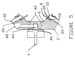
- Figure 5 is a cross sectional view of the fountain assembly of Figure 2 along line B-B.
- Figure 6 is a cross sectional view of the fountain assembly of Figure 2 along line A-A.
- Figure 7 is a cross sectional view of the fountain assembly of Figure 2 along line D-D.
- Figure 8 is a cross sectional view of the fountain assembly of Figure 2 along line C-C.
- Figure 9 is a side elevational view of the invention and shows a cross-sectional view of the air cylinders which are used in the fountain assembly.
- Figure 9a shows an enlarged portion of the view in Figure 9.
- Figure 10 is a side elevational view of the fountain assembly of the invention and shows the end seal lubrication system.
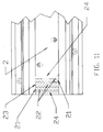
- Figure 11 is a top view of a composite radial surface seal in schematic form.
- the invention provides a fountain assembly for applying a fluid composition uniformly to the circumferential surface of a rotating transfer roller comprising an elongated frame having a concave channel formed on one side of the frame along the length thereof, the frame comprising a substantially inert, resilient, light weight, polymeric plastic material.
- a rigid, reinforcing brace fixed along substantially the entire length of said frame on an outer side thereof opposite the channel.
- a a pair of doctor blades are removably attached by clamping means on opposite sides of said channel and extend the length of the channel, the blades being positionable to contact the circumferential surface of the transfer roller.
- a pair of radial surface seals are secured to the fountain assembly at opposite ends of the cavity, the radial surface seals being positioned to form a resilient bulkhead with the ends of the doctor blades.
- the radial surface seals have a complementary curved edge for forming a sealing engagement with the circumferential surface of the transfer roller.
- the radial surface seals, doctor blades and concave channel form a closed chamber when positioned against the transfer roller.
- a pivoting support, bearing the fountain assembly is provided wherein the support is capable of alternately swiveling the fountain assembly toward and away from the transfer roller. Means are then present for providing a supply of a fluid composition into the channel.
- the invention also provides a fountain assembly for applying a fluid composition uniformly to the circumferential surface of a rotating transfer roller comprising an elongated frame having a concave channel formed on one side of said frame along the length thereof and a pair of doctor blades removably attached by clamping means on opposite sides of said channel and extending the length of said channel.
- the blades are positionable to contact the circumferential surface of the transfer roller.
- a pair of radial surface seals are secured to the fountain assembly at opposite ends of said cavity wherein the radial surface seals are positioned to form a resilient bulkhead with the ends of the doctor blades.
- the radial surface seals have a complementary curved edge for forming a sealing engagement with the circumferential surface of the transfer roller.
- Pivoting support means bear the fountain assembly and the support is capable of alternately swiveling the frame toward and away from the transfer roller.
- Air cylinder means are mounted between the pivoting support and the frame wherein the air cylinder means are capable of adjusting the position of the frame by thrusting the frame into and out of contact with the transfer roller. Means are present for providing a supply of a fluid composition into the channel.
- the invention further provides a fountain assembly for applying a fluid composition uniformly to the circumferential surface of a rotating transfer roller comprising an elongated frame having a concave channel formed on one side of the frame along the length thereof and a pair of doctor blades removably attached by clamping means on opposite sides of the channel and extending the length of the channel.
- the blades are positionable to contact the circumferential surface of the transfer roller.
- a pair of radial surface seals are secured to the fountain assembly at opposite ends of the cavity wherein the radial surface seals are positioned to form a resilient bulkhead with the ends of the doctor blades.
- the radial surface seals have a complementary curved edge for forming a sealing engagement with the circumferential surface of the transfer roller.
- the radial surface seals, doctor blades and concave channel form a closed chamber when positioned against the transfer roller.
- a plurality of washing nozzles is disposed along the channel which are capable of spraying a washing solution to the channel.
- Internal manifold means are within the frame for directing a washing fluid to the nozzles together with means for dispensing a controlled amount of a washing solution under pressure through the manifold and the nozzles.
- Pivoting support means bearing the fountain assembly is provided and is capable of alternately swiveling the fountain assembly toward and away from the transfer roller. Means are present for providing a supply of a fluid composition into the channel.
- the invention still further comprises a fountain assembly for applying a fluid composition uniformly to the circumferential surface of a rotating transfer roller. It has an elongated frame having a concave channel formed on one side of said frame along the length thereof and a pair of doctor blades removably attached by clamping means on opposite sides of the channel and extending the length of said channel, the blades being positionable to contact the circumferential surface of the transfer roller.
- a pair of radial surface seals are secured to the fountain assembly at opposite ends of the cavity, the radial surface seals being positioned to form a resilient bulkhead with the ends of the doctor blades and the radial surface seals have a complementary curved edge for forming a sealing engagement with the circumferential surface of the transfer roller.
- the said radial surface seals, doctor blades and concave channel form a closed chamber when positioned against the transfer roller.
- Pivoting support means bear the frame, the support means being capable of alternately swiveling the frame toward and away from the transfer roller.
- the assembly has means for providing a supply of a fluid composition into the channel.
- the assembly also has lubrication supply means comprising a manifold internal to the frame for directing lubricating fluid to the radial surface seals; and means for supplying a lubricating fluid to the manifold in an amount sufficient to maintain the radial surface seals moist with lubricating fluid.
- the invention still further provides a radial surface seal for the fountain assembly comprising a layer of an absorbent material and a layer of a closed cell, non-absorbing foam polymer on each opposite side of the absorbent material to define a composite.
- the composite has an outer edge contour which when positioned in the fountain assembly is capable of forming a resilient sealing engagement with the ends of the pair of doctor blades, the frame and the circumferential surface of a transfer roller.
- FIG. 1 shows a side view of the fountain assembly of the present invention and demonstrates its deployment with a rotating transfer roller, such as an anilox roller commonly used in flexographic printing.
- the assembly is shown to comprise an elongated fountain body or frame 2, which is composed of a light weight, substantially inert, resilient, polymeric plastic material such as high density polyethylene.
- inert is meant a material which is resistant to corrosion by the components of the compositions to be applied to the transfer roller, such as flexographic inks, as well as washing compositions.
- a light weight frame has a tendency to deflect under load and so the rear side of the frame is supported along its entire length by a rigid reinforcing brace 4, preferably composed of steel, to provide added strength.
- the reinforcing brace is fixed to the plastic frame along its entire length by a series of bolts 5.
- the front side of the frame has a concave channel 6 formed along the length its entire length.
- Coating composition such as a flexographic ink is supplied to the fountain assembly into this channel.
- On each side of the channel is a doctor blade 8.
- the doctor blades are configured to scrape against a rotating anilox roller 10 such that when an ink is fed into channel 6, it is applied to the surface of the roller 10 and excess ink is scraped off by the doctor blades 8 and returned to the channel.
- the doctor blades are fixed in place by means of clamp bars 12 which extend along the entire length of the fountain frame.
- the clamp bars are engaged along its entire length by a series of hand knobs 14.
- knobs 14 are hand turnable threaded shanks which pass through and abut the fountain frame 2 and engage the clamping bars 12 such that when the knobs are tightened, they pull the clamp bars against the doctor blades and retain the blades in place.
- each doctor blade 8 is positioned along its entire length on a continuous step at location 17. This is an important improvement over the prior art since this arrangement permits quick, positive doctor blade positioning.
- a sacrificial wear strip 16 At the base of each doctor blade is a sacrificial wear strip 16 which assists in the prevention of damage to the plastic frame body when metal doctor blades are used.
- the wear strip may consist of a resilient plastic material, such as a polyethylene strip which is positioned in a groove along the length of the frame at the doctor blade bases.
- a pair of seals 20, preferably made of an elastomer, are also positioned in grooves along the length of the frame abutting against each of the sides of the doctor blades. These seals prevent ink from seeping down behind the base of the doctor blades.
- the ends of the ink channel 6 must be capped at its ends in order to prevent ink runoff from its sides.
- abutting each end of the channel is an radial surface seal 22, which is held in place with an end seal holder 24 which is attached to the frame at each end of the channel.
- the end seal holders have a slotted section which maintain a fit between the seal and the holder thus securing the seal in place.
- the radial surface seals may be replaced simply by pulling them out of the holder without the use of tools.
- the end seal is radial in construction, that is, it has a rounded front edge which has substantially the same radius as the anilox roller so that it abuts the roller in use. This is best seen in Figure 1.
- this radial surface seal is a low cost, closed cell polyethylene foam material which is cut to fit the profile of the anilox roller and the contour of the fountain and doctor blades.
- the radial surface seal 22 is a three membered composite of a closed cell, non-absorbing foam elastomer 21, such as polyethylene foam on each side of a felt pad 23. Such a material provides an excellent seal between the roller, fountain chamber and doctor blades due to its resiliency.
- radial surface seal 22 is shown to be held in place with end seal holder 24. Each end seal holder is attached to frame 2 by means of screws 25.
- the radial surface seals are supplied with lubricating water or solvent composition which is supplied under pressure at continuous or regular pulsed intervals from a lubricant supply channel 19 which is an internal manifold within frame 2.
- the lubricant supply feeds lubrication reservoir 29 which in turn wicks through the radial surface seal. Leakage between the lubricant supply and the end seal is prevented by an appropriate gasket between the two.
- the lubricant is supplied to the composite radial surface seal with the result that friction between the seal and the transfer roller is substantially reduced. This provides an effective seal between the ink fountain chamber, doctor blades, and anilox roller and provides an inexpensive, replaceable seal with a much greater life expectancy that currently used seals.
- a cycled pulse of pressurized lubricant provides adequate lubrication.
- Such a lubricated system reduces the abrasive characteristics of inks on the end seals and reduces the wear characteristic of inks on the anilox roller at the end seal.
- the lubrication applied to the radial surface seals breaks down any ink build-up on the seal itself. This is important since dried flexographic inks are very abrasive.
- Such a lubricated radial surface seal is essentially unaffected by the rotation or speed of the roller.
- a pressurized lubricant cycle minimizes the amount of lubricant required to adequately lubricate the seal so that the desired seal life expectancy is attained.
- This invention essentially provides a universal doctor blade holder. As seen in Figure 5, when one side of the clamp bars 12 press against the doctor blade ends, a gap is formed between the frame 2 and the other end of the clamp bars. In order to prevent the clamp bars from becoming cantilevered, a spacer strip 26 is provided between the frame and the clamp bars. As shown in Figure 7, part 27 represents an locating pin for the spacer. The frame body and clamp bar, in conjunction with the spacer strips are able to accommodate different doctor blade thicknesses. A different doctor blade thickness can be used by simply changing the spacer strips in the assembly. Spacer strips may be composed of the same materials as are suitable for the doctor blades.
- the fountain assembly frame is supported by the overall coating or printing apparatus by means of a pivot shaft 28.
- Pivot shaft 28 extends parallel to the fountain frame along its length.
- the pivot shaft supports the weight of the fountain assembly and alternately swivels the assembly toward and away from the transfer roller.
- An improvement which the present invention provides over the prior art is that the fountain assembly is mounted on the pivot shaft by means of an arrangement of air cylinders positioned between the fountain and the pivot shaft.
- operators positioned a fountain assembly by swiveling it on a pivot shaft until the blades contact the anilox roller. This is disadvantageous because exact positioning of the blades is difficult and the blades tend to wear unevenly. This is particularly true with heavy weight, all metal fountain assemblies.
- the present invention mounts the fountain assembly to the pivot shaft by intermediate air cylinders 30.
- air cylinders 30 comprise a piston arrangement 32 fed by a controlled air supply 31.
- the piston arrangement 32 presses or retracts the fountain assembly frame and hence engages the doctor blades with the anilox roller. This provides for self compensating doctor blade tip wear and manufacturing tolerances, since pressure is variably applied to upper and lower doctor blades independently. The result is longer blade life.
- This system allows operators to repeat precise settings of the fountain.
- the air from the air supply 31 presses spherical bearing rod end 33 against the frame 2.
- the spherical bearing rod end 33 is attached to spherical bearing 35.
- a hex head bolt 37 which is coupled at its other end with sliding bushing 39 which slides in a bore within mounting blocks 41.
- the spherical bearing rod end is free to move in a linear fashion toward or away the frame 2 within the degree of freedom permitted by the cylinder bore end caps.
- the amount of such movement can vary as bushing 39 slides within its bore.
- Figure 9 shows a cross sectional view of one air cylinder, however, another is positioned adjacent to it and two more are set further down along the brace.
- four air cylinders are mounted between the pivot shaft and the brace to provide a fountain assembly which is essentially free floating against the transfer roller.
- the preferred arrangement of four air cylinders provide a four corner point pneumatic thrust loading arrangement. This arrangement is best seen in Figure 4.
- Rod ends and spherical bearings useful within the context of this invention include those available commercially from the Heim Division of Incom International, Inc. of Fairfield Connecticut.
- Air regulators on both the upper and lower sets of air cylinders provide the operator with the ability to accurately control doctor blade pressure.
- the brace 4 serves as a mounting surface for the air cylinders 30.
- ink or other coating composition is supplied to channel 6 of the fountain frame by means of internal ink supply ports 36. Excess ink or coating composition reverts back to a supply reservoir by overflow passageways 38 which are also internal to the frame. Ink can be drained from the fountain via passageways 43 by means of tapered ink drain leads 40 as seen in Figure 2A. This prevents stagnant ink from remaining in the fountain chamber. This also results in an automatic ink return system which assures that the fountain channel is always filled with ink. If desired, a transparent window can be provided at the overflow port location so that the operator can confirm that the fountain is filled with ink.
- Pneumatically operated piston drain valves 39 as shown at the break-away section of Figure 6, are positioned at each end of the fountain assembly to provide a quick and efficient means of controlling the return of ink from the fountain to storage reservoirs via ink returns and ink drains.
- Ink drain valves 39 are driven by an air supply provided through duct 34.
- the fountain frame is provided with an internal wash-up system.
- the base of channel 6 has a series of internal spray nozzles 42. By means of these nozzles, a supply of a washing solution is automatically fed to the fountain assembly.
- the nozzles 42 atomize and spray a metered amount of washing fluid under pressure over all parts of the assembly.
- the nozzles 42 are arranged in at least two rows along the entire length of the channel and spaced so that nozzles in one row are offset or staggered, rather than directly across from the nozzles in the next row as shown in Figure 2.
- This causes a spray in a criss-cross pattern which effectively cleans the fountain assembly.
- nozzles are directly across from one another, their spray patterns interfere with one another and cleaning is not as effective.
- This method is particularly effective for cleaning the underside of the doctor blades.
- the internal nozzles 42 are fed with water or a cleaning solution by internal manifolds 44.
- manifold seals 46 are positioned at the locations where the external water supply engages the manifold. Cleaning solution is supplied to the manifold from an outside source under pressure through supply ports 48.
- An electronic analog or digital logic controlled wash-up cycle permits automatic control of washing cycles. This includes automatic actuation of drain valves in the fountain to return ink to storage reservoirs, automatic valving of waste water to storage tanks, and calculated, pressurized bursts of water at specific intervals to minimize the use of water throughout the cycle. At the end of the cycle, all valving can be returned to its original state.
- the tapered ink drains also serve to remove waste water during the wash-up cycle.
Landscapes
- Inking, Control Or Cleaning Of Printing Machines (AREA)
Priority Applications (1)
| Application Number | Priority Date | Filing Date | Title |
|---|---|---|---|
| EP95109675A EP0688670B1 (fr) | 1992-12-30 | 1993-12-15 | Encrier |
Applications Claiming Priority (2)
| Application Number | Priority Date | Filing Date | Title |
|---|---|---|---|
| US07/998,732 US5410961A (en) | 1992-12-30 | 1992-12-30 | Fountain assembly |
| US998732 | 1992-12-30 |
Related Child Applications (1)
| Application Number | Title | Priority Date | Filing Date |
|---|---|---|---|
| EP95109675.9 Division-Into | 1993-12-15 |
Publications (2)
| Publication Number | Publication Date |
|---|---|
| EP0607574A1 true EP0607574A1 (fr) | 1994-07-27 |
| EP0607574B1 EP0607574B1 (fr) | 1996-05-01 |
Family
ID=25545515
Family Applications (2)
| Application Number | Title | Priority Date | Filing Date |
|---|---|---|---|
| EP93120184A Revoked EP0607574B1 (fr) | 1992-12-30 | 1993-12-15 | Encrier |
| EP95109675A Expired - Lifetime EP0688670B1 (fr) | 1992-12-30 | 1993-12-15 | Encrier |
Family Applications After (1)
| Application Number | Title | Priority Date | Filing Date |
|---|---|---|---|
| EP95109675A Expired - Lifetime EP0688670B1 (fr) | 1992-12-30 | 1993-12-15 | Encrier |
Country Status (3)
| Country | Link |
|---|---|
| US (1) | US5410961A (fr) |
| EP (2) | EP0607574B1 (fr) |
| DE (2) | DE69308896T2 (fr) |
Cited By (10)
| Publication number | Priority date | Publication date | Assignee | Title |
|---|---|---|---|---|
| FR2778140A1 (fr) * | 1998-05-01 | 1999-10-29 | Langston Corp | Appareil et procede de distribution d'encre/fluide de nettoyage a une lame d'etalement placee dans une chambre |
| EP0970810A1 (fr) * | 1998-06-25 | 2000-01-12 | Fischer & Krecke Gmbh & Co. | Procédé et dispositif pour nettoyer le système de transport d'encre d'une machine à imprimer |
| WO2003091025A1 (fr) * | 2002-04-25 | 2003-11-06 | Goss International Corporation | Ensemble rampe d'encrage integre conçu pour une presse a imprimer |
| EP1398152A1 (fr) * | 2002-09-09 | 2004-03-17 | Uteco Holding S.P.A. | Machine flexographique |
| WO2005005148A1 (fr) * | 2003-07-10 | 2005-01-20 | Comexi, Sa | Dispositif de fixation de feuillard de racloir dans un racloir de rouleau d'impression |
| EP1279500A3 (fr) * | 2001-07-25 | 2007-01-03 | MAN Roland Druckmaschinen AG | Procédé et dispositif de dosage d'un produit liquide dans une machine de traitement |
| WO2009089672A1 (fr) * | 2008-01-16 | 2009-07-23 | Zhuolin Tang | Racle pour une unité d'impression d'une machine à rainurer d'impression |
| ITUA20163914A1 (it) * | 2016-05-30 | 2017-11-30 | Celmacch Group S R L | Racla per macchina da stampa e suo montaggio |
| IT201900004241A1 (it) * | 2019-03-25 | 2020-09-25 | Koenig & Bauer Flexotecnica S P A | Macchina per stampa flessografica |
| DE102022121229A1 (de) * | 2022-08-23 | 2024-02-29 | Koenig & Bauer Ag | Farbwerk mit einer Schmiermittelzufuhr und Verfahren zum Abdichten einer Farbwanne |
Families Citing this family (34)
| Publication number | Priority date | Publication date | Assignee | Title |
|---|---|---|---|---|
| DE19516224C2 (de) * | 1995-05-03 | 1997-03-20 | Windmoeller & Hoelscher | Rakelvorrichtung für ein Spülfarbwerk einer Rotationsdruckmaschine |
| US5662041A (en) * | 1995-05-24 | 1997-09-02 | Trans Tech America, Inc. | Doctor blades for pad printing machines and machines including same |
| US5683508A (en) * | 1995-08-25 | 1997-11-04 | Fit Group, Inc. | Coating apparatus and method for dispensing a liquid, and draining and cleaning a coating apparatus |
| DE19536268C1 (de) | 1995-09-28 | 1997-02-06 | Windmoeller & Hoelscher | Rakelvorrichtung für ein Spülfarbwerk einer Rotationsdruckmaschine |
| US5832835A (en) * | 1996-07-12 | 1998-11-10 | Markem Corporation | Soft doctoring cup |
| DE19631301A1 (de) * | 1996-08-02 | 1998-02-05 | Gorter Cornelis | Farbkammerrakel für eine Druckmaschine |
| US5983797A (en) * | 1997-11-17 | 1999-11-16 | Howard W. DeMoore | End seal engaging bearer of anilox roller assembly |
| US6076463A (en) * | 1998-03-13 | 2000-06-20 | Heidelberger Druckmaschinen Ag | Ink metering device and method of metering ink |
| JP4271292B2 (ja) * | 1998-03-23 | 2009-06-03 | 株式会社小森コーポレーション | インキ装置 |
| CH693305A5 (fr) * | 1999-03-05 | 2003-05-30 | Bobst Sa | Dispositif d'encrage amovible pour une machine d'impression flexographique. |
| ES2192179T3 (es) * | 1999-06-22 | 2003-10-01 | Tresu Production As | Sistema de rasqueta. |
| SE517357C2 (sv) * | 1999-07-06 | 2002-05-28 | Aake Boeoese | Anordning för ändtätning vid en kammarrakel och en kammarrakel med en sådan ändtätnigsanordning |
| JP2001105571A (ja) * | 1999-10-13 | 2001-04-17 | Heidelberger Druckmas Ag | インキストック収容装置 |
| DE29918488U1 (de) * | 1999-10-20 | 1999-12-30 | MAN Roland Druckmaschinen AG, 63075 Offenbach | Bogenrotationsdruckmaschine mit Druckeinheiten für den Mehrfarbendruck und wenigstens einer Beschichtungseinheit |
| US6383296B1 (en) | 1999-11-22 | 2002-05-07 | Harris & Bruno Machine Co. | Chambered doctor blade with automatic cleanup and ink replacement |
| US6576059B2 (en) * | 1999-11-22 | 2003-06-10 | Harris & Bruno Company, Inc. | Chambered doctor blade system for water-based and UV-based coatings |
| DK200000237A (da) * | 2000-02-15 | 2001-08-16 | Tresu Anlaeg As | Bjælke for kammerrakel samt kammerrakel |
| DE10158157B4 (de) * | 2001-11-28 | 2006-09-07 | Koenig & Bauer Ag | Farbwerk einer Druckmaschine |
| ITMI20031539A1 (it) * | 2003-07-25 | 2003-10-24 | Percivalle Special Converting S A S Di Percivall | Unita' di inchiostrazione e raclatura per un gruppo di stampa e spalmatura rotocalcografica. |
| SE527080C2 (sv) * | 2004-05-05 | 2005-12-20 | Akeboose Internat Ab | Anordning och förfarande för kammarrakel |
| US7487724B1 (en) | 2006-05-09 | 2009-02-10 | Larry William Evans | Liquid transfer arrangement for applying a printing liquid to a printing surface |
| US7597761B2 (en) * | 2006-08-10 | 2009-10-06 | Van Denend Mark E | Sealing assembly for an ink chamber which includes self-lubricating anilox roll seal with improved blade/seal area |
| DE102007027385B4 (de) * | 2007-06-11 | 2011-06-16 | Windmöller & Hölscher Kg | Farbkammer für ein Farbwerk einer Rotationsdruckmaschine und Verfahren zur Herstellung einer solchen Farbkammer |
| DE102007027383A1 (de) * | 2007-06-11 | 2008-12-24 | Windmöller & Hölscher Kg | Farbkammerrakel in einem Farbwerk einer Rotationsdruckmaschine |
| US20090193990A1 (en) * | 2008-02-06 | 2009-08-06 | Van Denend Mark E | Seal for an Ink Chamber with Improved Blade/Seal Area |
| WO2010014619A2 (fr) * | 2008-07-28 | 2010-02-04 | Integrity Engineering, Inc. | Perfectionnements à des outils de tirage flexographique d’épreuves et procédés |
| US8474378B1 (en) | 2010-02-23 | 2013-07-02 | Valley Holdings, Llc | Chamber blade/sealing assembly for a printing press |
| US8925455B2 (en) | 2010-09-01 | 2015-01-06 | Anthony Foley | Self-lubricating seal for enclosed doctor blade assembly |
| US9248639B2 (en) * | 2011-06-03 | 2016-02-02 | Hewlett-Packard Development Company, L.P. | Imaging device having fluid container and method for collecting carrier fluid |
| US9296201B2 (en) | 2013-03-13 | 2016-03-29 | Probity Engineering, Llc | Ink fountain apparatus and method of adjusting ink flow for a flexographic printing apparatus |
| CN106573267B (zh) | 2014-04-04 | 2020-02-14 | 惠普印迪戈股份公司 | 流体施加 |
| CN112046128A (zh) * | 2019-06-05 | 2020-12-08 | 至善实业股份有限公司 | 凹版印刷机的同向封闭式刮刀装置 |
| US11517944B2 (en) * | 2019-12-19 | 2022-12-06 | Simec Group S.r.l. | Device for cleaning cylindrical rollers, machine comprising said device, and cleaning method |
| CN114536967A (zh) * | 2021-07-13 | 2022-05-27 | 渭南三立印刷机械有限公司 | 一种印刷机上的封闭式油墨刮刀 |
Citations (57)
| Publication number | Priority date | Publication date | Assignee | Title |
|---|---|---|---|---|
| US236566A (en) | 1881-01-11 | Inking apparatus for printing-machines | ||
| US1559871A (en) | 1924-03-29 | 1925-11-03 | Heyman John | Fabric-cutting machine |
| US1919283A (en) | 1931-12-22 | 1933-07-25 | Martin J Troy | Ink fountain divider and pad |
| US2218945A (en) | 1937-01-13 | 1940-10-22 | Akerlund & Rausing Ab | Inking device for printing machines |
| GB589259A (en) | 1945-03-21 | 1947-06-16 | Curran Brothers Ltd | Improvements in or relating to sealing devices for rotary shafts |
| US2442700A (en) | 1944-10-18 | 1948-06-01 | Cottrell C B & Sons Co | Ink fountain for printing presses |
| GB612178A (en) | 1945-06-13 | 1948-11-09 | Goss Printing Press Co Ltd | Improvements in or relating to inking mechanism for rotary intaglio printing presses |
| US2501944A (en) | 1943-07-10 | 1950-03-28 | Jaeger Machine Co | Sealing means for mixers or the like |
| US2744464A (en) | 1951-05-22 | 1956-05-08 | Hoe & Co R | Partitioned fountain rotary intaglio printing machines |
| US2795195A (en) | 1953-06-03 | 1957-06-11 | Du Pont | High pressure pumping method |
| US2887050A (en) | 1957-07-11 | 1959-05-19 | Samuel M Langston Co | Flexographic ink fountains |
| US3032007A (en) | 1959-05-01 | 1962-05-01 | Francis W Mccauliff | Coating head dike |
| US3339485A (en) | 1964-06-15 | 1967-09-05 | Bonnierfoeretagen Ab | Adjustable ink supply device in rotary printing presses |
| DE1263650B (de) | 1963-07-15 | 1968-03-21 | Guy Olney Conner | Maschine zum Abbau von Feststoffen, insbesondere Mineralien aus Lagerstaetten |
| US3585932A (en) | 1968-06-07 | 1971-06-22 | Wallace H Granger | Automatic inking system for rotary newspaper printing press |
| US3593663A (en) | 1969-06-03 | 1971-07-20 | Zerand Corp | Doctor blade assembly for printing equipment |
| US3701335A (en) | 1970-02-17 | 1972-10-31 | Feldmuehle Ag | Coating apparatus for sheet material |
| US3831517A (en) | 1972-12-22 | 1974-08-27 | Dayco Corp | Fountain divider |
| US4165688A (en) | 1977-04-14 | 1979-08-28 | Magna-Graphics Corporation | Ink dam for printing press |
| US4186661A (en) | 1978-02-27 | 1980-02-05 | Fmc Corporation | Flexographic inking system including a reverse angle doctor blade |
| US4213388A (en) | 1977-09-21 | 1980-07-22 | Windmoller & Holscher | Gearing for driving a plate cylinder of a printing press at a non-uniform speed |
| US4332194A (en) | 1979-11-09 | 1982-06-01 | M.A.N.-Roland Druckmaschinen Aktiengesellschaft | Arrangement for reducing vibration of cylinders in printing press |
| US4361089A (en) | 1980-10-20 | 1982-11-30 | Magna-Graphics Corporation | Multi-color rotary press |
| US4366754A (en) | 1978-04-07 | 1983-01-04 | Sarda Jean Lucien | Holder for ink separator on a drum of a printing press |
| US4408528A (en) | 1980-04-10 | 1983-10-11 | Veb Kombinat Polygraph "Werner Lamberz" Leipzig | Printing equipment with screw controlled doctor blade |
| US4408526A (en) | 1981-03-30 | 1983-10-11 | M.A.N.--Roland Druckmaschinen Aktiengesellschaft | No-play gear drive for printing machines |
| US4414900A (en) | 1980-11-15 | 1983-11-15 | M.A.N. Roland Druckmaschinen Aktiengesellschaft | Non-leaking printing ink trough |
| US4414895A (en) | 1981-06-19 | 1983-11-15 | Press Machinery Corporation Of Illinois | Method and apparatus for conversion of a printing press to offset printing |
| US4461211A (en) | 1981-07-29 | 1984-07-24 | Windmoller & Holscher | Flush inking mechanism for a rotary printing press |
| US4463675A (en) | 1980-12-01 | 1984-08-07 | Windmoller & Holscher | Doctor device |
| US4481883A (en) | 1982-06-04 | 1984-11-13 | Creusot-Loire | Low-blade inking mechanism with detachable ink duct troughs |
| US4503770A (en) | 1981-08-18 | 1985-03-12 | Cox Norman Victor | Printing machine doctor blades |
| US4513662A (en) | 1982-11-06 | 1985-04-30 | Koenig & Bauer Aktiengesellschaft | Ink fountain dividing key |
| US4515078A (en) | 1982-06-03 | 1985-05-07 | M.A.N.-Roland Druckmaschinen Ag | Doctor blade drive |
| US4554870A (en) | 1983-03-08 | 1985-11-26 | M.A.N.-Roland Druckmaschinen Aktiengesellschaft | Ink metering device for a printing machine having an ink trough-ink roller combination |
| US4569286A (en) | 1984-01-18 | 1986-02-11 | Basf Aktiengesellschaft | Apparatus for closing the gap between the ends of a gravure printing plate clamped on a forme cylinder |
| US4581995A (en) | 1985-06-07 | 1986-04-15 | Motter Printing Press Co. | Ink sealing assembly |
| US4590855A (en) | 1984-06-18 | 1986-05-27 | Printco Industries, Ltd. | Reverse angle doctor blade assembly with stationary end seal |
| US4617865A (en) | 1985-08-07 | 1986-10-21 | Ryco Graphic Manufacturing, Inc. | Liquid coater for a printing press with moveable inking roller and tray |
| US4635549A (en) | 1984-09-08 | 1987-01-13 | Basf Aktiengesellschaft | Method for closing the gap between the ends of gravure printing plates clamped on forme clyinders |
| US4655133A (en) | 1984-10-29 | 1987-04-07 | Harris Graphics Corporation | Ink fountain assembly and segmented film metering, blade |
| US4667595A (en) | 1984-10-30 | 1987-05-26 | Windmoller & Holscher | Inking system for multiple color printing by a single plate cylinder |
| US4676160A (en) | 1985-07-18 | 1987-06-30 | M.A.N.-Roland Druckmaschinen Aktiengesellschaft | Doctor blade for use in an inker of a printing machine |
| US4716826A (en) | 1984-08-01 | 1988-01-05 | Officine Meccaniche Giovanni Cerutti S.P.A. | Instantaneous adjustment device for a dotoring blade assembly operatively linked to a cylinder in a printing press |
| US4796528A (en) | 1987-05-29 | 1989-01-10 | M.A.N. Roland Druckmaschinen Ag | Separated ink fountain for a flexographic printing machine |
| US4821672A (en) | 1987-06-22 | 1989-04-18 | Nick Bruno | Doctor blade assembly with rotary end seals and interchangeable heads |
| WO1989007047A1 (fr) | 1988-02-01 | 1989-08-10 | Tresu A/S | Chambre de racle |
| US4876097A (en) | 1984-12-20 | 1989-10-24 | Rhone-Poulenc Sante | Compositions for coating feeding stuff additives intended for ruminants and feeding stuff additives thus coated |
| US4879949A (en) | 1988-05-18 | 1989-11-14 | Ildvaco Engineering A/S | Reverse angle doctor blade assembly |
| US4938133A (en) | 1988-09-22 | 1990-07-03 | Man Roland Druckmaschinen Ag | Printing machine having chambered doctor blade unit inker |
| US4964336A (en) | 1988-09-22 | 1990-10-23 | Man Roland Druckmaschinen Ag | Printing machine with separable compact inker including a chambered doctor blade unit |
| US5012736A (en) | 1987-09-21 | 1991-05-07 | Paper Converting Machine Company | Sealing assembly for liquid fountain |
| US5027513A (en) * | 1990-02-12 | 1991-07-02 | Allisontech Sales, Inc. | Seal relief doctor blade |
| US5125341A (en) * | 1991-05-15 | 1992-06-30 | Paper Converting Machine Company | Ink unit for printing press and method |
| EP0499382A1 (fr) * | 1991-02-14 | 1992-08-19 | Ward Holding Company, Inc. | Support pour racle et machine à imprimer avec ce support |
| US5150651A (en) | 1991-06-10 | 1992-09-29 | Flores Carlos R | Doctor-blade assembly for flexographic press |
| US5177752A (en) | 1989-06-30 | 1993-01-05 | Matsushita Electric Industrial Co., Ltd. | Optical pulse generator using gain-switched semiconductor laser |
Family Cites Families (16)
| Publication number | Priority date | Publication date | Assignee | Title |
|---|---|---|---|---|
| US3057327A (en) * | 1959-03-04 | 1962-10-09 | Time Inc | Blade controlling device for coating apparatus |
| US3135197A (en) * | 1961-10-19 | 1964-06-02 | Orville V Dutro | Ink fountain assembly for printing apparatus |
| US3186339A (en) * | 1963-07-17 | 1965-06-01 | Flynn & Emrich Company | Fluid operated fountain blade |
| US4026210A (en) * | 1975-04-24 | 1977-05-31 | Rotobind Ltd. | Printing apparatus and method |
| US4162501A (en) * | 1977-08-08 | 1979-07-24 | Silonics, Inc. | Ink supply system for an ink jet printer |
| DE3704433A1 (de) * | 1987-02-12 | 1988-08-25 | Frankenthal Ag Albert | Kurzfarbwerk |
| US4789432A (en) * | 1987-06-08 | 1988-12-06 | Thermo Electron Web Systems, Inc. | Doctoring apparatus |
| US4906335A (en) * | 1987-06-08 | 1990-03-06 | Thermo Electron Web System, Inc. | Doctoring apparatus |
| US5038681A (en) * | 1988-01-19 | 1991-08-13 | Jimek International Ab | Control method and apparatus for spray dampener |
| JPH072200Y2 (ja) * | 1988-04-18 | 1995-01-25 | 三菱重工業株式会社 | 印刷装置 |
| US5003876A (en) * | 1989-02-10 | 1991-04-02 | The Ward Machinery Company | Printing apparatus with dual inking system |
| US5010819A (en) * | 1989-09-22 | 1991-04-30 | Oxy-Dry Corporation | Blanket cleaning apparatus with selectively engageable flicker bar |
| US5040457A (en) * | 1989-10-10 | 1991-08-20 | Rockwell International Corporation | Printing press dampener |
| US5085144A (en) * | 1990-05-03 | 1992-02-04 | Motter Printing Press Co. | Ink fountain apparatus |
| US5040456A (en) * | 1990-11-09 | 1991-08-20 | U.S. Graphics Ltd. | Screen printing frame |
| DE4036677C1 (fr) | 1990-11-17 | 1991-10-24 | Blaupunkt-Werke Gmbh, 3200 Hildesheim, De |
-
1992
- 1992-12-30 US US07/998,732 patent/US5410961A/en not_active Expired - Lifetime
-
1993
- 1993-12-15 EP EP93120184A patent/EP0607574B1/fr not_active Revoked
- 1993-12-15 DE DE69308896T patent/DE69308896T2/de not_active Expired - Fee Related
- 1993-12-15 DE DE69302465T patent/DE69302465T2/de not_active Revoked
- 1993-12-15 EP EP95109675A patent/EP0688670B1/fr not_active Expired - Lifetime
Patent Citations (57)
| Publication number | Priority date | Publication date | Assignee | Title |
|---|---|---|---|---|
| US236566A (en) | 1881-01-11 | Inking apparatus for printing-machines | ||
| US1559871A (en) | 1924-03-29 | 1925-11-03 | Heyman John | Fabric-cutting machine |
| US1919283A (en) | 1931-12-22 | 1933-07-25 | Martin J Troy | Ink fountain divider and pad |
| US2218945A (en) | 1937-01-13 | 1940-10-22 | Akerlund & Rausing Ab | Inking device for printing machines |
| US2501944A (en) | 1943-07-10 | 1950-03-28 | Jaeger Machine Co | Sealing means for mixers or the like |
| US2442700A (en) | 1944-10-18 | 1948-06-01 | Cottrell C B & Sons Co | Ink fountain for printing presses |
| GB589259A (en) | 1945-03-21 | 1947-06-16 | Curran Brothers Ltd | Improvements in or relating to sealing devices for rotary shafts |
| GB612178A (en) | 1945-06-13 | 1948-11-09 | Goss Printing Press Co Ltd | Improvements in or relating to inking mechanism for rotary intaglio printing presses |
| US2744464A (en) | 1951-05-22 | 1956-05-08 | Hoe & Co R | Partitioned fountain rotary intaglio printing machines |
| US2795195A (en) | 1953-06-03 | 1957-06-11 | Du Pont | High pressure pumping method |
| US2887050A (en) | 1957-07-11 | 1959-05-19 | Samuel M Langston Co | Flexographic ink fountains |
| US3032007A (en) | 1959-05-01 | 1962-05-01 | Francis W Mccauliff | Coating head dike |
| DE1263650B (de) | 1963-07-15 | 1968-03-21 | Guy Olney Conner | Maschine zum Abbau von Feststoffen, insbesondere Mineralien aus Lagerstaetten |
| US3339485A (en) | 1964-06-15 | 1967-09-05 | Bonnierfoeretagen Ab | Adjustable ink supply device in rotary printing presses |
| US3585932A (en) | 1968-06-07 | 1971-06-22 | Wallace H Granger | Automatic inking system for rotary newspaper printing press |
| US3593663A (en) | 1969-06-03 | 1971-07-20 | Zerand Corp | Doctor blade assembly for printing equipment |
| US3701335A (en) | 1970-02-17 | 1972-10-31 | Feldmuehle Ag | Coating apparatus for sheet material |
| US3831517A (en) | 1972-12-22 | 1974-08-27 | Dayco Corp | Fountain divider |
| US4165688A (en) | 1977-04-14 | 1979-08-28 | Magna-Graphics Corporation | Ink dam for printing press |
| US4213388A (en) | 1977-09-21 | 1980-07-22 | Windmoller & Holscher | Gearing for driving a plate cylinder of a printing press at a non-uniform speed |
| US4186661A (en) | 1978-02-27 | 1980-02-05 | Fmc Corporation | Flexographic inking system including a reverse angle doctor blade |
| US4366754A (en) | 1978-04-07 | 1983-01-04 | Sarda Jean Lucien | Holder for ink separator on a drum of a printing press |
| US4332194A (en) | 1979-11-09 | 1982-06-01 | M.A.N.-Roland Druckmaschinen Aktiengesellschaft | Arrangement for reducing vibration of cylinders in printing press |
| US4408528A (en) | 1980-04-10 | 1983-10-11 | Veb Kombinat Polygraph "Werner Lamberz" Leipzig | Printing equipment with screw controlled doctor blade |
| US4361089A (en) | 1980-10-20 | 1982-11-30 | Magna-Graphics Corporation | Multi-color rotary press |
| US4414900A (en) | 1980-11-15 | 1983-11-15 | M.A.N. Roland Druckmaschinen Aktiengesellschaft | Non-leaking printing ink trough |
| US4463675A (en) | 1980-12-01 | 1984-08-07 | Windmoller & Holscher | Doctor device |
| US4408526A (en) | 1981-03-30 | 1983-10-11 | M.A.N.--Roland Druckmaschinen Aktiengesellschaft | No-play gear drive for printing machines |
| US4414895A (en) | 1981-06-19 | 1983-11-15 | Press Machinery Corporation Of Illinois | Method and apparatus for conversion of a printing press to offset printing |
| US4461211A (en) | 1981-07-29 | 1984-07-24 | Windmoller & Holscher | Flush inking mechanism for a rotary printing press |
| US4503770A (en) | 1981-08-18 | 1985-03-12 | Cox Norman Victor | Printing machine doctor blades |
| US4515078A (en) | 1982-06-03 | 1985-05-07 | M.A.N.-Roland Druckmaschinen Ag | Doctor blade drive |
| US4481883A (en) | 1982-06-04 | 1984-11-13 | Creusot-Loire | Low-blade inking mechanism with detachable ink duct troughs |
| US4513662A (en) | 1982-11-06 | 1985-04-30 | Koenig & Bauer Aktiengesellschaft | Ink fountain dividing key |
| US4554870A (en) | 1983-03-08 | 1985-11-26 | M.A.N.-Roland Druckmaschinen Aktiengesellschaft | Ink metering device for a printing machine having an ink trough-ink roller combination |
| US4569286A (en) | 1984-01-18 | 1986-02-11 | Basf Aktiengesellschaft | Apparatus for closing the gap between the ends of a gravure printing plate clamped on a forme cylinder |
| US4590855A (en) | 1984-06-18 | 1986-05-27 | Printco Industries, Ltd. | Reverse angle doctor blade assembly with stationary end seal |
| US4716826A (en) | 1984-08-01 | 1988-01-05 | Officine Meccaniche Giovanni Cerutti S.P.A. | Instantaneous adjustment device for a dotoring blade assembly operatively linked to a cylinder in a printing press |
| US4635549A (en) | 1984-09-08 | 1987-01-13 | Basf Aktiengesellschaft | Method for closing the gap between the ends of gravure printing plates clamped on forme clyinders |
| US4655133A (en) | 1984-10-29 | 1987-04-07 | Harris Graphics Corporation | Ink fountain assembly and segmented film metering, blade |
| US4667595A (en) | 1984-10-30 | 1987-05-26 | Windmoller & Holscher | Inking system for multiple color printing by a single plate cylinder |
| US4876097A (en) | 1984-12-20 | 1989-10-24 | Rhone-Poulenc Sante | Compositions for coating feeding stuff additives intended for ruminants and feeding stuff additives thus coated |
| US4581995A (en) | 1985-06-07 | 1986-04-15 | Motter Printing Press Co. | Ink sealing assembly |
| US4676160A (en) | 1985-07-18 | 1987-06-30 | M.A.N.-Roland Druckmaschinen Aktiengesellschaft | Doctor blade for use in an inker of a printing machine |
| US4617865A (en) | 1985-08-07 | 1986-10-21 | Ryco Graphic Manufacturing, Inc. | Liquid coater for a printing press with moveable inking roller and tray |
| US4796528A (en) | 1987-05-29 | 1989-01-10 | M.A.N. Roland Druckmaschinen Ag | Separated ink fountain for a flexographic printing machine |
| US4821672A (en) | 1987-06-22 | 1989-04-18 | Nick Bruno | Doctor blade assembly with rotary end seals and interchangeable heads |
| US5012736A (en) | 1987-09-21 | 1991-05-07 | Paper Converting Machine Company | Sealing assembly for liquid fountain |
| WO1989007047A1 (fr) | 1988-02-01 | 1989-08-10 | Tresu A/S | Chambre de racle |
| US4879949A (en) | 1988-05-18 | 1989-11-14 | Ildvaco Engineering A/S | Reverse angle doctor blade assembly |
| US4938133A (en) | 1988-09-22 | 1990-07-03 | Man Roland Druckmaschinen Ag | Printing machine having chambered doctor blade unit inker |
| US4964336A (en) | 1988-09-22 | 1990-10-23 | Man Roland Druckmaschinen Ag | Printing machine with separable compact inker including a chambered doctor blade unit |
| US5177752A (en) | 1989-06-30 | 1993-01-05 | Matsushita Electric Industrial Co., Ltd. | Optical pulse generator using gain-switched semiconductor laser |
| US5027513A (en) * | 1990-02-12 | 1991-07-02 | Allisontech Sales, Inc. | Seal relief doctor blade |
| EP0499382A1 (fr) * | 1991-02-14 | 1992-08-19 | Ward Holding Company, Inc. | Support pour racle et machine à imprimer avec ce support |
| US5125341A (en) * | 1991-05-15 | 1992-06-30 | Paper Converting Machine Company | Ink unit for printing press and method |
| US5150651A (en) | 1991-06-10 | 1992-09-29 | Flores Carlos R | Doctor-blade assembly for flexographic press |
Cited By (13)
| Publication number | Priority date | Publication date | Assignee | Title |
|---|---|---|---|---|
| FR2778140A1 (fr) * | 1998-05-01 | 1999-10-29 | Langston Corp | Appareil et procede de distribution d'encre/fluide de nettoyage a une lame d'etalement placee dans une chambre |
| EP0970810A1 (fr) * | 1998-06-25 | 2000-01-12 | Fischer & Krecke Gmbh & Co. | Procédé et dispositif pour nettoyer le système de transport d'encre d'une machine à imprimer |
| EP1279500A3 (fr) * | 2001-07-25 | 2007-01-03 | MAN Roland Druckmaschinen AG | Procédé et dispositif de dosage d'un produit liquide dans une machine de traitement |
| US7007604B2 (en) | 2002-04-25 | 2006-03-07 | Goss International Corporation | Integrated ink rail assembly for a printing press |
| WO2003091025A1 (fr) * | 2002-04-25 | 2003-11-06 | Goss International Corporation | Ensemble rampe d'encrage integre conçu pour une presse a imprimer |
| US7171899B2 (en) | 2002-04-25 | 2007-02-06 | Goss International Corporation | Integrated ink rail assembly for a printing press |
| EP1398152A1 (fr) * | 2002-09-09 | 2004-03-17 | Uteco Holding S.P.A. | Machine flexographique |
| US6792855B2 (en) | 2002-09-09 | 2004-09-21 | Uteco Holding S.P.A | Flexographic machine |
| WO2005005148A1 (fr) * | 2003-07-10 | 2005-01-20 | Comexi, Sa | Dispositif de fixation de feuillard de racloir dans un racloir de rouleau d'impression |
| WO2009089672A1 (fr) * | 2008-01-16 | 2009-07-23 | Zhuolin Tang | Racle pour une unité d'impression d'une machine à rainurer d'impression |
| ITUA20163914A1 (it) * | 2016-05-30 | 2017-11-30 | Celmacch Group S R L | Racla per macchina da stampa e suo montaggio |
| IT201900004241A1 (it) * | 2019-03-25 | 2020-09-25 | Koenig & Bauer Flexotecnica S P A | Macchina per stampa flessografica |
| DE102022121229A1 (de) * | 2022-08-23 | 2024-02-29 | Koenig & Bauer Ag | Farbwerk mit einer Schmiermittelzufuhr und Verfahren zum Abdichten einer Farbwanne |
Also Published As
| Publication number | Publication date |
|---|---|
| DE69308896D1 (de) | 1997-04-17 |
| US5410961A (en) | 1995-05-02 |
| EP0607574B1 (fr) | 1996-05-01 |
| EP0688670B1 (fr) | 1997-03-12 |
| DE69302465D1 (de) | 1996-06-05 |
| EP0688670A1 (fr) | 1995-12-27 |
| DE69308896T2 (de) | 1997-06-19 |
| DE69302465T2 (de) | 1996-09-12 |
Similar Documents
| Publication | Publication Date | Title |
|---|---|---|
| EP0688670B1 (fr) | Encrier | |
| US4497250A (en) | Ink Fountain | |
| US4590855A (en) | Reverse angle doctor blade assembly with stationary end seal | |
| US6883427B2 (en) | Methods for applying ink and washing-up after printing | |
| US4461211A (en) | Flush inking mechanism for a rotary printing press | |
| CA1062955A (fr) | Encreur sous pression pour impression en creux | |
| US4041864A (en) | Method and apparatus for inking printing plates | |
| US5012736A (en) | Sealing assembly for liquid fountain | |
| US5239925A (en) | Ink distribution apparatus | |
| US6360660B1 (en) | Doctor blade systems | |
| US20090035037A1 (en) | Doctor blade chamber for high viscous ink | |
| DE19729985C2 (de) | Vorrichtung zum Lackieren von Bedruckstoffen in einem Offsetdruckwerk einer Rotationsdruckmaschine | |
| US6516720B2 (en) | Printing machines | |
| US5085144A (en) | Ink fountain apparatus | |
| JPS60242065A (ja) | 輪転印刷機の版胴の版盤にインキを着けるインキ装置 | |
| US6571710B1 (en) | Keyless inker for a printing press | |
| US5440982A (en) | Inking system for a printing press | |
| US6119595A (en) | Gravure printing press with encapsulated ink applicator and method | |
| DE602004007001T2 (de) | Farbwerk und rakeleinheit für rotationstiefdruck und verteilanordnung | |
| JPH07214757A (ja) | 回転円柱体に形成された凹みへの液体の充填方法および装置 | |
| US5636566A (en) | Gravure printing unit for a rotary press | |
| DE10253194A1 (de) | Vorrichtung und Verfahren zum Einfärben der Walze einer Rotationsdruckmaschine | |
| EP1389523B1 (fr) | Machine à imprimer ou à enduire | |
| DE4208295A1 (de) | Einfaerbevorrichtung fuer eine rasterwalze | |
| US5404818A (en) | Inking system for printing ink rollers |
Legal Events
| Date | Code | Title | Description |
|---|---|---|---|
| PUAI | Public reference made under article 153(3) epc to a published international application that has entered the european phase |
Free format text: ORIGINAL CODE: 0009012 |
|
| AK | Designated contracting states |
Kind code of ref document: A1 Designated state(s): CH DE FR GB IT LI |
|
| 17P | Request for examination filed |
Effective date: 19940803 |
|
| 17Q | First examination report despatched |
Effective date: 19950216 |
|
| GRAA | (expected) grant |
Free format text: ORIGINAL CODE: 0009210 |
|
| AK | Designated contracting states |
Kind code of ref document: B1 Designated state(s): CH DE FR GB IT LI |
|
| XX | Miscellaneous (additional remarks) |
Free format text: TEILANMELDUNG 95109675.9. |
|
| REG | Reference to a national code |
Ref country code: CH Ref legal event code: NV Representative=s name: ISLER & PEDRAZZINI AG PATENTANWAELTE |
|
| REF | Corresponds to: |
Ref document number: 69302465 Country of ref document: DE Date of ref document: 19960605 |
|
| ITF | It: translation for a ep patent filed | ||
| ET | Fr: translation filed | ||
| PLBI | Opposition filed |
Free format text: ORIGINAL CODE: 0009260 |
|
| PLBQ | Unpublished change to opponent data |
Free format text: ORIGINAL CODE: EPIDOS OPPO |
|
| PLBF | Reply of patent proprietor to notice(s) of opposition |
Free format text: ORIGINAL CODE: EPIDOS OBSO |
|
| 26 | Opposition filed |
Opponent name: TRESU A/S Effective date: 19970130 |
|
| PLBF | Reply of patent proprietor to notice(s) of opposition |
Free format text: ORIGINAL CODE: EPIDOS OBSO |
|
| PLBF | Reply of patent proprietor to notice(s) of opposition |
Free format text: ORIGINAL CODE: EPIDOS OBSO |
|
| RDAH | Patent revoked |
Free format text: ORIGINAL CODE: EPIDOS REVO |
|
| APAC | Appeal dossier modified |
Free format text: ORIGINAL CODE: EPIDOS NOAPO |
|
| APAE | Appeal reference modified |
Free format text: ORIGINAL CODE: EPIDOS REFNO |
|
| APAC | Appeal dossier modified |
Free format text: ORIGINAL CODE: EPIDOS NOAPO |
|
| REG | Reference to a national code |
Ref country code: GB Ref legal event code: IF02 |
|
| PGFP | Annual fee paid to national office [announced via postgrant information from national office to epo] |
Ref country code: GB Payment date: 20021126 Year of fee payment: 10 |
|
| PGFP | Annual fee paid to national office [announced via postgrant information from national office to epo] |
Ref country code: DE Payment date: 20021129 Year of fee payment: 10 |
|
| PGFP | Annual fee paid to national office [announced via postgrant information from national office to epo] |
Ref country code: FR Payment date: 20021217 Year of fee payment: 10 |
|
| PGFP | Annual fee paid to national office [announced via postgrant information from national office to epo] |
Ref country code: CH Payment date: 20021224 Year of fee payment: 10 |
|
| APAC | Appeal dossier modified |
Free format text: ORIGINAL CODE: EPIDOS NOAPO |
|
| RDAG | Patent revoked |
Free format text: ORIGINAL CODE: 0009271 |
|
| STAA | Information on the status of an ep patent application or granted ep patent |
Free format text: STATUS: PATENT REVOKED |
|
| REG | Reference to a national code |
Ref country code: CH Ref legal event code: PL |
|
| 27W | Patent revoked |
Effective date: 20030521 |
|
| GBPR | Gb: patent revoked under art. 102 of the ep convention designating the uk as contracting state |
Free format text: 20030521 |
|
| APAH | Appeal reference modified |
Free format text: ORIGINAL CODE: EPIDOSCREFNO |