EP0607781A1 - Condensateur électrolytique solide - Google Patents
Condensateur électrolytique solide Download PDFInfo
- Publication number
- EP0607781A1 EP0607781A1 EP94100029A EP94100029A EP0607781A1 EP 0607781 A1 EP0607781 A1 EP 0607781A1 EP 94100029 A EP94100029 A EP 94100029A EP 94100029 A EP94100029 A EP 94100029A EP 0607781 A1 EP0607781 A1 EP 0607781A1
- Authority
- EP
- European Patent Office
- Prior art keywords
- film
- capacitor
- solid electrolytic
- resin sheathing
- oxygen
- Prior art date
- Legal status (The legal status is an assumption and is not a legal conclusion. Google has not performed a legal analysis and makes no representation as to the accuracy of the status listed.)
- Ceased
Links
- 239000003990 capacitor Substances 0.000 title claims abstract description 91
- 239000007787 solid Substances 0.000 title claims abstract description 36
- 229920005989 resin Polymers 0.000 claims abstract description 37
- 239000011347 resin Substances 0.000 claims abstract description 37
- 239000002322 conducting polymer Substances 0.000 claims abstract description 18
- 229920001940 conductive polymer Polymers 0.000 claims abstract description 18
- 239000000126 substance Substances 0.000 claims abstract description 15
- 239000007784 solid electrolyte Substances 0.000 claims abstract description 14
- 239000010407 anodic oxide Substances 0.000 claims abstract description 11
- QVGXLLKOCUKJST-UHFFFAOYSA-N atomic oxygen Chemical compound [O] QVGXLLKOCUKJST-UHFFFAOYSA-N 0.000 claims abstract description 11
- 239000001301 oxygen Substances 0.000 claims abstract description 11
- 229910052760 oxygen Inorganic materials 0.000 claims abstract description 11
- 229910052751 metal Inorganic materials 0.000 claims abstract description 9
- 239000002184 metal Substances 0.000 claims abstract description 9
- 229910052715 tantalum Inorganic materials 0.000 claims description 9
- GUVRBAGPIYLISA-UHFFFAOYSA-N tantalum atom Chemical compound [Ta] GUVRBAGPIYLISA-UHFFFAOYSA-N 0.000 claims description 9
- 229920000647 polyepoxide Polymers 0.000 claims description 8
- 229910052782 aluminium Inorganic materials 0.000 claims description 7
- XAGFODPZIPBFFR-UHFFFAOYSA-N aluminium Chemical compound [Al] XAGFODPZIPBFFR-UHFFFAOYSA-N 0.000 claims description 7
- 239000003822 epoxy resin Substances 0.000 claims description 7
- 229920000414 polyfuran Polymers 0.000 claims description 5
- 229920000123 polythiophene Polymers 0.000 claims description 5
- 150000004696 coordination complex Chemical class 0.000 claims description 3
- 150000001923 cyclic compounds Chemical class 0.000 claims description 3
- 150000001875 compounds Chemical class 0.000 abstract description 5
- 229920000642 polymer Polymers 0.000 abstract description 2
- 238000004519 manufacturing process Methods 0.000 description 10
- 238000000034 method Methods 0.000 description 9
- 230000008569 process Effects 0.000 description 9
- BQCADISMDOOEFD-UHFFFAOYSA-N Silver Chemical compound [Ag] BQCADISMDOOEFD-UHFFFAOYSA-N 0.000 description 8
- 229910052709 silver Inorganic materials 0.000 description 8
- 239000004332 silver Substances 0.000 description 8
- 239000008188 pellet Substances 0.000 description 7
- OKKJLVBELUTLKV-UHFFFAOYSA-N Methanol Chemical compound OC OKKJLVBELUTLKV-UHFFFAOYSA-N 0.000 description 6
- 230000004888 barrier function Effects 0.000 description 6
- OKTJSMMVPCPJKN-UHFFFAOYSA-N Carbon Chemical compound [C] OKTJSMMVPCPJKN-UHFFFAOYSA-N 0.000 description 4
- NBIIXXVUZAFLBC-UHFFFAOYSA-N Phosphoric acid Chemical compound OP(O)(O)=O NBIIXXVUZAFLBC-UHFFFAOYSA-N 0.000 description 4
- KAESVJOAVNADME-UHFFFAOYSA-N Pyrrole Chemical compound C=1C=CNC=1 KAESVJOAVNADME-UHFFFAOYSA-N 0.000 description 4
- YADSGOSSYOOKMP-UHFFFAOYSA-N dioxolead Chemical compound O=[Pb]=O YADSGOSSYOOKMP-UHFFFAOYSA-N 0.000 description 4
- 229910002804 graphite Inorganic materials 0.000 description 4
- 239000010439 graphite Substances 0.000 description 4
- NUJOXMJBOLGQSY-UHFFFAOYSA-N manganese dioxide Chemical compound O=[Mn]=O NUJOXMJBOLGQSY-UHFFFAOYSA-N 0.000 description 4
- 229920000128 polypyrrole Polymers 0.000 description 4
- 239000000243 solution Substances 0.000 description 4
- 239000011888 foil Substances 0.000 description 3
- 239000002245 particle Substances 0.000 description 3
- LFQSCWFLJHTTHZ-UHFFFAOYSA-N Ethanol Chemical compound CCO LFQSCWFLJHTTHZ-UHFFFAOYSA-N 0.000 description 2
- 229910000147 aluminium phosphate Inorganic materials 0.000 description 2
- 230000000903 blocking effect Effects 0.000 description 2
- 238000010438 heat treatment Methods 0.000 description 2
- 239000012212 insulator Substances 0.000 description 2
- 229910044991 metal oxide Inorganic materials 0.000 description 2
- 230000009467 reduction Effects 0.000 description 2
- 238000005245 sintering Methods 0.000 description 2
- 238000012360 testing method Methods 0.000 description 2
- XLYOFNOQVPJJNP-UHFFFAOYSA-N water Substances O XLYOFNOQVPJJNP-UHFFFAOYSA-N 0.000 description 2
- OXHNLMTVIGZXSG-UHFFFAOYSA-N 1-Methylpyrrole Chemical compound CN1C=CC=C1 OXHNLMTVIGZXSG-UHFFFAOYSA-N 0.000 description 1
- FLDCSPABIQBYKP-UHFFFAOYSA-N 5-chloro-1,2-dimethylbenzimidazole Chemical compound ClC1=CC=C2N(C)C(C)=NC2=C1 FLDCSPABIQBYKP-UHFFFAOYSA-N 0.000 description 1
- 239000001741 Ammonium adipate Substances 0.000 description 1
- NLZUEZXRPGMBCV-UHFFFAOYSA-N Butylhydroxytoluene Chemical compound CC1=CC(C(C)(C)C)=C(O)C(C(C)(C)C)=C1 NLZUEZXRPGMBCV-UHFFFAOYSA-N 0.000 description 1
- 239000004593 Epoxy Substances 0.000 description 1
- PLNNMJRJPYQBBJ-UHFFFAOYSA-N [Fe+3].CCCCCCCCCCCCOS(=O)(=O)C1=CC=CC=C1 Chemical compound [Fe+3].CCCCCCCCCCCCOS(=O)(=O)C1=CC=CC=C1 PLNNMJRJPYQBBJ-UHFFFAOYSA-N 0.000 description 1
- 235000019293 ammonium adipate Nutrition 0.000 description 1
- 239000007864 aqueous solution Substances 0.000 description 1
- 150000001491 aromatic compounds Chemical class 0.000 description 1
- 125000003118 aryl group Chemical group 0.000 description 1
- 230000007423 decrease Effects 0.000 description 1
- 238000003795 desorption Methods 0.000 description 1
- 238000009792 diffusion process Methods 0.000 description 1
- 239000006185 dispersion Substances 0.000 description 1
- 239000002019 doping agent Substances 0.000 description 1
- 230000000694 effects Effects 0.000 description 1
- 239000003925 fat Substances 0.000 description 1
- 239000011261 inert gas Substances 0.000 description 1
- 230000002401 inhibitory effect Effects 0.000 description 1
- FYMCOOOLDFPFPN-UHFFFAOYSA-K iron(3+);4-methylbenzenesulfonate Chemical compound [Fe+3].CC1=CC=C(S([O-])(=O)=O)C=C1.CC1=CC=C(S([O-])(=O)=O)C=C1.CC1=CC=C(S([O-])(=O)=O)C=C1 FYMCOOOLDFPFPN-UHFFFAOYSA-K 0.000 description 1
- 239000000463 material Substances 0.000 description 1
- 238000000465 moulding Methods 0.000 description 1
- 239000003921 oil Substances 0.000 description 1
- 150000002926 oxygen Chemical class 0.000 description 1
- 125000004430 oxygen atom Chemical group O* 0.000 description 1
- 229920006254 polymer film Polymers 0.000 description 1
- 238000006116 polymerization reaction Methods 0.000 description 1
- 150000004032 porphyrins Chemical class 0.000 description 1
- 239000000843 powder Substances 0.000 description 1
- 230000004044 response Effects 0.000 description 1
- 229920002050 silicone resin Polymers 0.000 description 1
- 229910000679 solder Inorganic materials 0.000 description 1
- PCCVSPMFGIFTHU-UHFFFAOYSA-N tetracyanoquinodimethane Chemical compound N#CC(C#N)=C1C=CC(=C(C#N)C#N)C=C1 PCCVSPMFGIFTHU-UHFFFAOYSA-N 0.000 description 1
- 238000003466 welding Methods 0.000 description 1
Images


Classifications
-
- H—ELECTRICITY
- H01—ELECTRIC ELEMENTS
- H01G—CAPACITORS; CAPACITORS, RECTIFIERS, DETECTORS, SWITCHING DEVICES, LIGHT-SENSITIVE OR TEMPERATURE-SENSITIVE DEVICES OF THE ELECTROLYTIC TYPE
- H01G9/00—Electrolytic capacitors, rectifiers, detectors, switching devices, light-sensitive or temperature-sensitive devices; Processes of their manufacture
- H01G9/004—Details
- H01G9/08—Housing; Encapsulation
Definitions
- the present invention relates to a solid electrolytic capacitor and more particularly, to a solid electrolytic capacitor having a conducting polymer as a solid electrolyte.
- the capacitor of the first example has a capacitor element 20.
- the element 20 is composed of an anode body 11, an anode wire 16 fixed on the top face of the anode body 11, a dielectric film 12 made of anodic-oxide which covers the bottom and side faces of the anode body 11, a metallic oxide film 19 as a solid electrolyte which is formed on the dielectric film 12 and is made of manganese dioxide, lead dioxide or the like, and a cathode film 14 which is formed on the dielectric film 12 and is made of electrically conductive paste such as graphite, silver or the like.
- the anode body 11 is made of metal having film-forming properties and valve actions such as tantalum, aluminum or the like and the surface area of the body 11 is enlarged.
- a lead frame 15b is connected to the end of the anode wire 16 and a lead frame 15a is connected to the cathode film 14 using a electrically conductive paste film 21 made of silver or the like.
- the capacitor element 20 and the bottom portions of the lead frames 15a and 15b are buried in a parallelepiped resin sheathing 18 made of epoxy resin.
- the other portions of the lead frames 15a and 15b project from the resin sheathing 18 and bent like an "L" character along the surfaces of the sheathing 18.
- a second example of conventional solid electrolytic capacitors is disclosed in the Japanese Non-Examined Patent Publication No. 52 - 79255.
- 7, 7', 8, 8'-tetracyanoquinodimethane (TCNQ) complex is employed as the solid electrolyte, instead of the metallic oxide film 19 made of manganese dioxide, lead dioxide or the like in the first example.
- TCNQ tetracyanoquinodimethane
- a solid electrolytic capacitor which employs a conducting polymer of the aromatic compounds such as polypyrrole with a high electrical conductivity as the solid electrolyte, and its capacitor element is buried in a molded resin sheathing made of epoxy or silicone resin.
- the capacitor employing the conducting polymer of the aromatic series has a disadvantage that the conducting polymer is easy to be oxidized. Therefore, when the capacitor is held in a high-temperature condition, oxygen contained in the atmospheric air diffuses through the resin sheathing to oxide the conducting polymer, and as a result, the Equivalent Series Resistance (ESR) of the capacitor at high-frequencies increases due to reduction of its electric conductivity.
- ESR Equivalent Series Resistance
- third and fourth examples of conventional solid electrolytic capacitors are developed, which are disclosed in the Japanese Non-Examined Patent Publication Nos. 3 - 109714 and 3 - 109712, respectively.
- a capacitor element 40 is composed of an anode body 21, an anode wire 26 fixed on the top face of the anode body 21, a conducting polypyrrole film 23 which covers the bottom and side faces of the anode body 21, a cathode film 24 which is formed on the conducting polypyrrole film 23 and is made of electrically conductive paste, and a barrier film 30 formed on the cathode film 24 for blocking or inhibiting oxygen to reach the capacitor element 40.
- the barrier layer 30 is made of resin.
- a lead frame 25b is connected to the end of the anode wire 26 and a lead frame 25a is connected to the cathode film 24 at the bottom face of the element 40.
- the capacitor of the fourth example is substantially similar in configuration to that of the third example other than that a barrier layer is made of metal instead of resin.
- a heat-treatment process as a part of the fabrication sequence is carried out under an inert-gas atmosphere.
- the part of the fabrication sequence is that from a process of forming a conducting polymer film to a process prior to that of forming a resin sheathing, or that from a process subsequent to a process of forming a conducting polymer film to a process of forming a resin sheathing.
- Fig. 3 shows a seventh example of conventional solid electrolytic capacitors, which is disclosed in the Japanese Non-Examined Utility-Model publication No. 1-121918.
- a capacitor element 50 is covered with an insulator frame 42 so that there is a gap between the surface of the element 50 and the frame 42.
- the gap is filled with resin or fats and oils 43 which contain no oxygen atom in the structural formula or which generate no activated oxygen.
- a resin sheathing (not shown) covers the entire surface of the frame 42.
- the barrier film 30 is formed for blocking oxygen diffusion through the resin sheathing 28 and then, the sheathing 28 is formed thereon. As a result, there is a disadvantage that an additional process for providing the barrier film 30 is required.
- the capacitor element 40 is required to be heated at a high temperature to make the metal film as the barrier film, for example, 200 to 300 °C in the case of solder. Therefore, there arises a phenomenon of "dopant desorption" so that the conducting polypyrrole film 23 decreases in electrical conductivity, resulting in increase of the ESR at high-frequencies.
- the part of the fabrication sequence is required to be carried out in a closed casing or chamber. Therefore, working efficiency becomes very low, which means that they are unsuitable for mass production.
- the insulator frames 42 it is difficult for the insulator frames 42 to cover the individual capacitor elements 50 and position them at desired states. Besides, the fabrication cost of the capacitor becomes higher due to the frames 42.
- an object of the present invention is to provide a solid electrolytic capacitor superior in high-temperature endurance.
- Another object of the present invention is to provide a solid electrolytic capacitor in which its electrical conductivity does not reduce due to oxygen contained in the atmospheric air and/or heat applied during its fabrication sequence without reduction of working efficiency.
- Still another object of the present invention is to provide a solid electrolytic capacitor which needs no additional part or component and provides no increase in cost.
- a solid electrolytic capacitor according the present invention includes a capacitor element and a resin sheathing which covers the entirety of the element.
- the element has an anode body made of metal having film-forming properties, a dielectric film made of anodic-oxide which covers the anode body, a conducting polymer compound film as a solid electrolyte formed on the dielectric film, and a cathode film formed on the polymer film.
- the resin sheathing contains a substance for absorbing oxygen dispersed therein.
- the oxygen-absorbing substance is dispersed in the resin sheathing, so that oxygen containing in the atmospheric air can be inhibited to reach the capacitor element through the resin sheathing. In addition, excessive heat does not applied to the capacitor during the fabrication sequence.
- the solid electrolytic capacitor is very difficult to be reduced in electrical conductivity due to oxygen contained in the atmospheric air and heat applied during its fabrication sequence. This means that the capacitor is superior in high-temperature endurance.
- the capacitor Since the dispersion of the oxygen-absorbing substance in the resin sheathing is sufficient for high-temperature endurance, the capacitor needs no additional part or component and provide no increase in cost. Further, working efficiency does not reduced.
- Fig. 1 is a cross section showing first and second conventional solid electrolytic capacitors.
- Fig. 2 is a cross section showing third and fourth conventional solid electrolytic capacitors.
- Fig. 3 is a cross section showing a seventh conventional solid electrolytic capacitor.
- Fig. 4 is a cross section of a solid electrolytic capacitor according to a first example of the present invention.
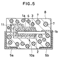
- Fig. 5 is a cross section of a solid electrolytic capacitor according to a third example of the present invention.
- the solid electrolytic capacitor according the present invention includes the capacitor element and the resin sheathing which covers the entirety of the element.
- the capacitor element may be of any structure if it contains the anode body, the dielectric film made of anodic-oxide, the conducting polymer compound film as the solid electrolyte, and the cathode film.
- the anode body may be made of any metal having film-forming properties.
- the anode body is a sintered body or metal foil or leaf of tantalum, aluminum or the like.
- the dielectric film is made of anodic-oxide of the metal making the anode body.
- the conducting polymer compound film as a solid electrolyte may be made of any conducting polymer compound. However, preferably, it is made of a cyclic compound, for example, polypyrrol, polythiophen and polyfuran, and their derivatives. An example of the derivatives is a polymer of N-methylpyrrole.
- the cathode film may be made of any conducting film. Preferably, it is made of an electrically conductive paste such as graphite, silver or the like.
- the resin sheathing contains the oxygen-absorbing substance dispersed therein.
- the substance is a bivalent metalcomplex, for example, metalloporphyrin and metallosalcomine and their derivatives.
- Fig. 3 shows a solid electrolytic capacitor of a first embodiment, which has a capacitor element 10 buried in a parallelepiped resin sheathing 8.
- the capacitor element 10 is composed of a tantalum anode body 1, a tantalum anode wire 6 fixed on the top face of the anode body 1, a dielectric film 2 of anodic-oxide which covers the bottom and side faces of the anode body 1, a conducting polypyrrol film 3 as a solid electrolyte which is formed on the dielectric film 2, and a cathode film 4 of electrically conductive paste such as graphite, silver or the like which is formed on the dielectric film 2.
- the anode body 1 is made of a sintered body of tantalum having film-forming properties and valve actions.
- a lead frame 5b is connected to the end of the anode wire 6 and a lead frame 5a is connected to the cathode film 4 using a silver paste film 11.
- the capacitor element 10 and the bottom portions of the lead frames 5a and 5b are buried in the parallelepiped resin sheathing 8 made of epoxy resin.
- the other portions of the lead frames 5a and 5b project from the resin sheathing 8 and bent like an "L" character along the surfaces of the sheathing 8.
- the resin sheathing 8 contains particles 7 of a bivalent metallic complex dispersed therein as the oxygen-absorbing substance.
- the solid electrolytic capacitor having the above-described structure was practically fabricated and tested to confirm its advantages or effects according to the following sequence:
- First, the rectangular parallepiped anode body 1 was prepared by sintering tantalum powders.
- the anode wire 6 was fixed at the top face of the anode body 1 during the sintering process.
- the anode body 1 was 3.5 mm x 3.0 mm in planar shape and was 1.5 mm in thickness.
- the tantalum anode body 1 was anodic-oxidized in an aqueous solution of phosphoric acid with an applied voltage of 90 volt.
- the anode body 1 thus anodic-oxidized was washed and dried to get a pellet whose bottom and side faces were covered with a dielectric film 2 of anodic-oxide.
- the pellet with the dielectric film 2 was dipped into a methanol solution of iron (III) dodecylbenzenesulfonate whose concentration is 20 wt% at room temperature, and then dried at 60 °C.
- the pellet was dipped into a water solution of pyrrol whose concentration is 1 mol % and held in 30 minutes therein.
- the conducting polypyrrol film 3 was formed on the surface of the pellet due to polymerization of pyrrol.
- the element 10 with the polypyrrol film 3 was washed by ethanol and dried. Then, the electrically conductive paste film was formed on the polypyrrol film 3 as the cathode film 4. Thus, the capacitor element 10 was obtained.
- the lead frame 5a is connected to the cathode film 4 using the silver paste film 11 at the bottom and side faces of the anode body 1.
- the lead frame 5b was connected to the end of the tantalum anode wire 6 by welding.
- the epoxy resin sheathing 8 was formed by molding so that the element 10 was entirely buried into the sheathing 8.
- the epoxy resin contains the particles 7 of the bivalent metallic complex such as porphyrin, salcomine and derivatives of the bivalent metallic complex as the oxygen-absorbing substance.
- the capacitor was tested about electrostatic capacitance at 120 Hz, tangent of a dielectric loss angle ⁇ at 120 Hz and ESR at 100 Khz.
- the testing results are as follows: With the capacitor of the first embodiment, capacitance at 120 Hz was 15.0 ⁇ F, tan ⁇ was 2.0 % at 120 Hz and ESR at 100 kHz was 80 m ⁇ . The same tests were carried out after holding the capacitor at 105 °C in 500 hours, and as a result, capacitance at 120 Hz was 14.9 ⁇ F, tan ⁇ at 120 Hz was 2.2 % and ESR at 100 kHz was 85 m ⁇ . It was seen from the results that the capacitor of the first embodiment is superior in high-temperature endurance.
- the conventional capacitors was made through the same sequence other than that the resin sheathing does not contain the oxygen-absorbing substance.
- a solid electrolytic capacitor of a second embodiment was made by the same fabrication sequence as that of the first embodiment excepting that a methanol solution of iron (III) p-toluenesulfonate whose concentration is 20 wt% was employed in the process of forming the conducting polypyrrol film 3.
- capacitance at 120 Hz was 15.0 ⁇ F
- tan ⁇ was 2.0 % at 120 Hz
- ESR at 100 kHz was 80 m ⁇ .
- capacitance at 120 Hz became 14.9 ⁇ F
- tan ⁇ at 120 Hz became 2.3 %
- ESR at 100 kHz became 88 m ⁇ .
- the capacitor of the second embodiment is also superior in high-temperature endurance.
- Fig. 4 shows a solid electrolytic capacitor of a third embodiment, which has a capacitor element 10a buried in a parallelepiped resin sheathing 8.
- the capacitor element 10a is composed of an aluminum anode body 1a, a dielectric film 2 of anodic-oxide which covers the bottom and side faces of the anode body 1a, a conducting polypyrrol film 3 as a solid electrolyte which is formed on the dielectric film 2, and a cathode film 4 of electrically conductive paste such as graphite, silver or the like which is formed on the dielectric film 2.
- the anode body 1 is made of a foil or leaf of aluminum having film-forming properties and valve actions, different from the first and second embodiments.
- a lead frame 5b is connected to the end of the anode wire 6 and a lead frame 5a is connected to the cathode film 4 using a silver paste film 11.
- the capacitor element 10a and the bottom portions of the lead frames 5a and 5b are buried in the parallelepiped resin sheathing 8 made of epoxy resin.
- the other portions of the lead frames 5a and 5b project from the resin sheathing 8 and bent like an "L" character along the surfaces of the sheathing 8.
- the resin sheathing 8 also contains particles 7 of a bivalent metallic complex dispersed therein as the oxygen-absorbing substance.
- the solid electrolytic capacitor having the above-described structure was made by the following fabrication sequence: First, the anode body 1a was prepared using an aluminum foil or leaf whose surface area was enlarged. The anode body 1 was 5 mm x 3 mm in planar shape and was 150 ⁇ m in thickness.
- the aluminum anode body 1a was electrolytic-oxidized in ammonium adipate with an applied voltage of 90 volt.
- the anode body 1a thus electrolytic-oxidized was washed and dried to get a pellet whose bottom and side faces were covered with the dielectric film 2 of anodic-oxide.
- the pellet with the dielectric film 2 was processed by the same sequence as that of the first embodiment and then , the solid electrolytic capacitor shown in Fig. 5 was obtained.
- capacitance at 120 Hz was 1.5 ⁇ F
- tan ⁇ at 120 Hz was 1.5 %
- ESR at 100 kHz was 52 m ⁇ .
- capacitance at 120 Hz became 1.45 ⁇ F
- tan ⁇ at 120 Hz became 1.7 %
- ESR at 100 kHz became 54 m ⁇ .
- the capacitor of the third embodiment is also superior in high-temperature endurance.
Landscapes
- Engineering & Computer Science (AREA)
- Power Engineering (AREA)
- Microelectronics & Electronic Packaging (AREA)
- Polyoxymethylene Polymers And Polymers With Carbon-To-Carbon Bonds (AREA)
- Fixed Capacitors And Capacitor Manufacturing Machines (AREA)
Applications Claiming Priority (2)
| Application Number | Priority Date | Filing Date | Title |
|---|---|---|---|
| JP16493A JPH07118436B2 (ja) | 1993-01-05 | 1993-01-05 | 固体電解コンデンサ |
| JP164/93 | 1993-01-05 |
Publications (1)
| Publication Number | Publication Date |
|---|---|
| EP0607781A1 true EP0607781A1 (fr) | 1994-07-27 |
Family
ID=11466398
Family Applications (1)
| Application Number | Title | Priority Date | Filing Date |
|---|---|---|---|
| EP94100029A Ceased EP0607781A1 (fr) | 1993-01-05 | 1994-01-03 | Condensateur électrolytique solide |
Country Status (2)
| Country | Link |
|---|---|
| EP (1) | EP0607781A1 (fr) |
| JP (1) | JPH07118436B2 (fr) |
Cited By (1)
| Publication number | Priority date | Publication date | Assignee | Title |
|---|---|---|---|---|
| US5694287A (en) * | 1994-09-02 | 1997-12-02 | Nec Corporation | Solid electrolytic capacitor with conductive polymer as solid electrolyte and method of manufacturing the same |
Families Citing this family (2)
| Publication number | Priority date | Publication date | Assignee | Title |
|---|---|---|---|---|
| JP3070446B2 (ja) * | 1995-07-28 | 2000-07-31 | 日本電気株式会社 | 固体電解コンデンサ |
| JP4642257B2 (ja) * | 2001-03-09 | 2011-03-02 | 日本ケミコン株式会社 | 固体電解コンデンサ |
Citations (3)
| Publication number | Priority date | Publication date | Assignee | Title |
|---|---|---|---|---|
| JPH01140621A (ja) * | 1987-11-26 | 1989-06-01 | Nitsuko Corp | 固体電解コンデンサ |
| JPH03109713A (ja) * | 1989-09-25 | 1991-05-09 | Kao Corp | 固体コンデンサ |
| JPH03109714A (ja) * | 1989-09-25 | 1991-05-09 | Kao Corp | 固体電解コンデンサ |
-
1993
- 1993-01-05 JP JP16493A patent/JPH07118436B2/ja not_active Expired - Lifetime
-
1994
- 1994-01-03 EP EP94100029A patent/EP0607781A1/fr not_active Ceased
Patent Citations (3)
| Publication number | Priority date | Publication date | Assignee | Title |
|---|---|---|---|---|
| JPH01140621A (ja) * | 1987-11-26 | 1989-06-01 | Nitsuko Corp | 固体電解コンデンサ |
| JPH03109713A (ja) * | 1989-09-25 | 1991-05-09 | Kao Corp | 固体コンデンサ |
| JPH03109714A (ja) * | 1989-09-25 | 1991-05-09 | Kao Corp | 固体電解コンデンサ |
Non-Patent Citations (2)
| Title |
|---|
| PATENT ABSTRACTS OF JAPAN vol. 13, no. 393 (E - 814) 31 August 1989 (1989-08-31) * |
| PATENT ABSTRACTS OF JAPAN vol. 15, no. 304 (E - 1096) 5 August 1991 (1991-08-05) * |
Cited By (1)
| Publication number | Priority date | Publication date | Assignee | Title |
|---|---|---|---|---|
| US5694287A (en) * | 1994-09-02 | 1997-12-02 | Nec Corporation | Solid electrolytic capacitor with conductive polymer as solid electrolyte and method of manufacturing the same |
Also Published As
| Publication number | Publication date |
|---|---|
| JPH06204099A (ja) | 1994-07-22 |
| JPH07118436B2 (ja) | 1995-12-18 |
Similar Documents
| Publication | Publication Date | Title |
|---|---|---|
| KR0159127B1 (ko) | 고체 전해 콘덴서 및 그 제조방법 | |
| TWI478189B (zh) | 固體電解電容器及其製造方法 | |
| EP2422350B1 (fr) | Condensateurs électrolytiques en polymère à haute tension et haute efficacité | |
| US7352563B2 (en) | Capacitor assembly | |
| EP0895259B1 (fr) | Condensateur à électrolyte solide utilisant des polymères conducteurs et sa méthode de fabrication | |
| JP2019047130A (ja) | 密封されたコンデンサアセンブリ | |
| EP0654804B1 (fr) | Condensateur à électrolyte solide | |
| EP3828906B1 (fr) | Condensateur électrolytique | |
| US6661646B2 (en) | Niobium capacitor and method of manufacture thereof | |
| KR20110027631A (ko) | 리세스 채널을 구비하는 전해 캐패시터 어셈블리 및 제조방법 | |
| KR102734046B1 (ko) | 고체 전해질 커패시터 | |
| KR20120010176A (ko) | 다수의 캐소드 종단들을 구비하는 고체 전해질 캐패시터 어셈블리 | |
| JPH05159987A (ja) | 固体電解コンデンサ | |
| EP1898433B1 (fr) | Condensateur à électrolyte solide et son procédé de production | |
| US20090089990A1 (en) | Method for manufacturing solid electrolytic capacitor | |
| EP0607781A1 (fr) | Condensateur électrolytique solide | |
| KR101098796B1 (ko) | 칩형 고체전해 캐패시터 및 이것의 제조방법 | |
| CN102177562B (zh) | 体电容器和方法 | |
| KR102894860B1 (ko) | 탄탈 커패시터 | |
| JPH03256313A (ja) | アルミニウム固体電解コンデンサ | |
| KR102141023B1 (ko) | 고체 전해 콘덴서용 전해액 | |
| JP4632134B2 (ja) | 固体電解コンデンサの製造方法 | |
| JPS622519A (ja) | 固体電解コンデンサの製造方法 | |
| JPH03116812A (ja) | 固体電解コンデンサ | |
| JP2005311014A (ja) | ニオブ固体電解コンデンサ |
Legal Events
| Date | Code | Title | Description |
|---|---|---|---|
| PUAI | Public reference made under article 153(3) epc to a published international application that has entered the european phase |
Free format text: ORIGINAL CODE: 0009012 |
|
| AK | Designated contracting states |
Kind code of ref document: A1 Designated state(s): DE FR |
|
| 17P | Request for examination filed |
Effective date: 19940608 |
|
| 17Q | First examination report despatched |
Effective date: 19950126 |
|
| STAA | Information on the status of an ep patent application or granted ep patent |
Free format text: STATUS: THE APPLICATION HAS BEEN REFUSED |
|
| 18R | Application refused |
Effective date: 19950805 |