EP0607785A1 - Méthode et appareil pour le meulage des bords de bandes de roulement - Google Patents
Méthode et appareil pour le meulage des bords de bandes de roulement Download PDFInfo
- Publication number
- EP0607785A1 EP0607785A1 EP94100035A EP94100035A EP0607785A1 EP 0607785 A1 EP0607785 A1 EP 0607785A1 EP 94100035 A EP94100035 A EP 94100035A EP 94100035 A EP94100035 A EP 94100035A EP 0607785 A1 EP0607785 A1 EP 0607785A1
- Authority
- EP
- European Patent Office
- Prior art keywords
- tread
- grinding
- edge
- wing
- wing tip
- Prior art date
- Legal status (The legal status is an assumption and is not a legal conclusion. Google has not performed a legal analysis and makes no representation as to the accuracy of the status listed.)
- Granted
Links
- 238000000034 method Methods 0.000 title claims abstract description 43
- 239000000463 material Substances 0.000 claims abstract description 7
- 238000007493 shaping process Methods 0.000 claims abstract description 5
- 239000005060 rubber Substances 0.000 description 13
- 238000007788 roughening Methods 0.000 description 7
- 230000009471 action Effects 0.000 description 3
- 239000011324 bead Substances 0.000 description 2
- 230000007246 mechanism Effects 0.000 description 2
- UONOETXJSWQNOL-UHFFFAOYSA-N tungsten carbide Chemical compound [W+]#[C-] UONOETXJSWQNOL-UHFFFAOYSA-N 0.000 description 2
- 239000004698 Polyethylene Substances 0.000 description 1
- 229910000831 Steel Inorganic materials 0.000 description 1
- 239000004568 cement Substances 0.000 description 1
- 239000011248 coating agent Substances 0.000 description 1
- 238000000576 coating method Methods 0.000 description 1
- 230000006866 deterioration Effects 0.000 description 1
- 239000004744 fabric Substances 0.000 description 1
- 239000012530 fluid Substances 0.000 description 1
- 230000006872 improvement Effects 0.000 description 1
- 239000007788 liquid Substances 0.000 description 1
- 230000002093 peripheral effect Effects 0.000 description 1
- -1 polyethylene Polymers 0.000 description 1
- 229920000573 polyethylene Polymers 0.000 description 1
- 230000008569 process Effects 0.000 description 1
- 230000009467 reduction Effects 0.000 description 1
- 238000005201 scrubbing Methods 0.000 description 1
- 238000000926 separation method Methods 0.000 description 1
- 239000007787 solid Substances 0.000 description 1
- 239000010959 steel Substances 0.000 description 1
- 239000000126 substance Substances 0.000 description 1
- 230000003746 surface roughness Effects 0.000 description 1
- 238000004073 vulcanization Methods 0.000 description 1
- 239000004636 vulcanized rubber Substances 0.000 description 1
Images




Classifications
-
- B—PERFORMING OPERATIONS; TRANSPORTING
- B24—GRINDING; POLISHING
- B24B—MACHINES, DEVICES, OR PROCESSES FOR GRINDING OR POLISHING; DRESSING OR CONDITIONING OF ABRADING SURFACES; FEEDING OF GRINDING, POLISHING, OR LAPPING AGENTS
- B24B5/00—Machines or devices designed for grinding surfaces of revolution on work, including those which also grind adjacent plane surfaces; Accessories therefor
- B24B5/36—Single-purpose machines or devices
- B24B5/366—Single-purpose machines or devices for grinding tyres
-
- B—PERFORMING OPERATIONS; TRANSPORTING
- B29—WORKING OF PLASTICS; WORKING OF SUBSTANCES IN A PLASTIC STATE IN GENERAL
- B29D—PRODUCING PARTICULAR ARTICLES FROM PLASTICS OR FROM SUBSTANCES IN A PLASTIC STATE
- B29D30/00—Producing pneumatic or solid tyres or parts thereof
- B29D30/06—Pneumatic tyres or parts thereof (e.g. produced by casting, moulding, compression moulding, injection moulding, centrifugal casting)
- B29D30/52—Unvulcanised treads, e.g. on used tyres; Retreading
Definitions
- This invention relates to an improved method and apparatus for grinding a tread edge or wing tip to remove material from, roughen, and shape its surface.
- Schelkmann in British Patent No. 1,552,841, filed October 7, 1976, illustrates a tread molded with a network of passages to assist in the evacuation of gaseous inclusions between the tread internal surfaces and the layer of bonding rubber on the prepared tire carcass.
- This patent further describes a method of coating the internal surface of the tread with unsaturated rubber to prevent deterioration of the tread internal surfaces during storage.
- the method for removing material from and shaping an edge of a precured tread comprises the steps of:
- the method of grinding the wing tip (110) may be employed by turning an annular tread (100) inside out such that the radially inner casing engaging (102) surface of the tread (100) is radially outward and the ground engaging tread surface (101) is radially inward.
- the tread (100) is mounted over an axially rotatable drum (60) and a tension mechanism (200) such that the tread (100) is centered on and supported by the drum (60).
- the mounted tread (100) is placed in tension by stretching the tread (100) to a predetermined circumferential length.
- the drum (60) is then rotated at a predetermined angular velocity.
- the casing engaging surface (102) of the tread can be buffed as described in U.S. Patent Application Serial No.
- a tread buffing wheel (51) is axially rotated to a predetermined angular velocity.
- the buffing wheel (51) is then placed in contact with the rotating tread (100), the buffing wheel (51) axis of rotation being aligned relative to the axis of rotation of the drum.
- the internal surface of the tread is buffed to a predetermined roughness with some of the grooves formed by wing buffing means 80, these grooves extending axially toward a tread edge.
- wing tips (110) are ground in the following manner, first a pair of guides (72) engage the axial exterior surfaces (104,106) of the tread (100), then a pair of rotating grinding wheels (77,78) engage each wing tip (110) thereby grinding the tips (110) sufficiently such that the inner and outer surfaces (112,114) of the wing tip (110) intersect and are roughened.
- the rotating grinding wheels (77,78) are then removed from tread contact.
- the tread (100) is removed from the drum (60) and tension mechanism (200), and a bonding cement is applied to the buffed and ground surfaces of the tread (100).
- the cemented surfaces are then covered with a polyethylene liner, and the ground contacting tread surfaces are then turned radially outward.
- a preferred apparatus (10) for buffing an annular tread (100) comprises a frame (21), a means (60) for supporting the tread, a means for stretching the tread (200), a center tread buffing means (50), a main drive motor, a pair of tread edge buffing means (81,82), and a means for rotating the tread edge buffing means (90A,90B).
- the means (60) for supporting the tread (100) is axially rotatable and mounted to the frame.
- the means (200) for stretching the tread is axially rotatable and has an axis of rotation parallel to the axis of rotation of the means (60) for supporting the tread.
- the center tread buffing means (50) has a curved surface capable of being brought into contact with the tread (100) for buffing a radially inner casing engaging tread surface (102).
- the buffing produces circumferentially extending minute grooves or brush marks of substantially even depth.
- the main drive means for rotating the mounted tread (100) about one or more axis also rotates the center tread buffing means (50).
- the pair of edge buffing means (81,82) buff the edges of the tread (100) with minute grooves or brush marks that are of substantially even depth and extend axially outward.
- the edge buffing means (81,82) are rotated by the means (90A,90B) for rotating the edge buffing means.
- the wing tip or edge grinding means (70) comprises a guide means (72) for positioning the edge or wing and supporting the tread, two pairs of grinding wheels (77,78), the rotating edge or wing tip grinding wheels (77,78) being brought into contact with the edge or wing tip (110), thereby grinding the axially inner and outer surfaces (112,114) of the edge or wing tip (110) shaping and forming the surfaces such that at least one surface is chamfered intersecting the other surface.
- Axial and “axially” means lines or directions that are parallel to the axis of rotation of the tire.
- “Buffed” means a procedure whereby the surface of an elastomeric tread or casing is roughened. The roughening removes oxidized material and permits better bonding.
- Center plane means the plane perpendicular to the axis of rotation of the tread and passing through the axial center of the tread.
- “Casing” means the carcass, belt structure, beads, sidewalls, and all other components of the tire including a layer of unvulcanized rubber to facilitate the assembly of the tread, the tread and undertread being excluded.
- the casing may be new, unvulcanized rubber or previously vulcanized rubber to be fitted with a new tread.
- Equatorial plane means the plane perpendicular to the tire's axis of rotation and passing through the center of its tread;
- Pneumatic tire means a laminated mechanical device of generally toroidal shape (usually an open torus) having beads and a tread and made of rubber, chemicals, fabric and steel or other materials. When mounted on the wheel of a motor vehicle, the tire through its tread provides a traction and contains the fluid or gaseous matter, usually air, that sustains the vehicle load.
- Ring and radially means directions radially toward or away from the axis of rotation of the tire
- Replacement tread refers to a premolded and precured tread.
- Retreading means the procedure of refurbishing a tread worn tire by removing the old tread and replacing it with a precured tread or a "hot capped” tread.
- Thread means a molded rubber component which, when bonded to a tire casing, includes that portion of the tire which comes into contact with the road when the tire is normally inflated and under normal load.
- Washings means the radial inward extension of the tread located at axial extremes of the tread, the inner surface of the wing being an extension of the inner casing contacting surface of the tread.
- Figure 1 illustrates a side view of the tread mounted on the preferred embodiment buffing and grinding apparatus.
- Figure 2 illustrates a view specifically highlighting the wing tip grinding means.
- Figure 3 is a view taken along lines 3-3 of Figure 2 illustrating the guide means and the grinding means in the retracted position relative to the tread.
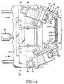
- Figure 4 is a view similar to Figure 3, depicting the guide means extended.
- Figure 5 is a view similar to Figure 4 showing the guide means extended and moved into the tread contacting position.
- Figure 6 is a view similar to Figure 5 depicting the wing tip grinding wheels moved into contact with the wing tips of the tread.
- Figure 7A illustrates a tread wing tip after grinding.
- Figure 7B illustrates a wing tip prior to grinding.
- Figure 8 illustrates a tread wing tip, as ground according to the invention, attached to a tire casing.
- Figures 1 through 6 illustrate the preferred embodiment apparatus 10.
- the basic apparatus is similar to the apparatus disclosed in U.S. Patent Application Serial No. 07/833,208, incorporated herein by reference.
- the illustrated apparatus is particularly adapted to buff and grind precured winged treads of an annular configuration.
- the method and apparatus as described is also suitable for grinding the edge of a flat tread or strip of tread of precured rubber with or without wings.
- the apparatus 10 as illustrated has a tread support drum 60 and a tension roller assembly 200. Mounted onto the drum 60 and the tension roller assembly 200 is an annular precured wing tread 100. The tread 100, when mounted to the apparatus 10, is turned inside out such that the ground contacting surface 101 is facing radially inward and the casing engaging surface 102 is radially outwardly facing.
- the apparatus has a center tread buffer assembly 50 and a wing or edge buffer assembly 80.
- the support drum 60 and the center tread buffer assembly 50 are driven by a main drive motor (not illustrated). A speed rotation reduction is accomplished such that the drum 60 rotates at an angular velocity or rpm substantially less than the center tread buffing assembly 50.
- the wing or edge buffing assembly 80 buffs the inner surface 111 of the wing or edge, the wing inner tread surface 111 being an axial extension of the tread inner surface 102 and including the tread edge.
- the wing buffer assembly 80 is powered by two 7-1/2 hp motors 90A and 90B (shown in Fig. 1). The motors are connected to the buffer assembly 80 by two drive shafts 91A and 91B.
- the tread 100 is shown mounted over the tread support drum 60 and a tension roller assembly 200.
- the tension roller assembly 200 is pivotally attached to the enclosure 22.
- the tension roller 201 is pivoted by actuating a cylinder. As the cylinder extends, the tension roller 201 axis of rotation is moved, increasing the distance between the axis of rotation of the drum 60 and the tension roller 201 axis. This relative movement increases the tension on the tread 100.
- the center tread buffing wheel 51 is rotated in a counterclockwise rotation while the tread 100 is slowly rotated in a counterclockwise direction.
- the center tread buffing wheel 51 roughens the inner tread surface 102 creating visually observable circumferential grooves.
- the wing or edge buffing assembly 80 has two oppositely rotating wing or edge buffing wheels 82 and 83, respectively. These wheels are rotated in opposite directions such that the wing's inner surfaces 102 are buffed under a tensile scrubbing action.
- the wing wheels 82,83 are mounted to a second support arm 85.
- the wing wheels 82,83 are axially movable and are spaced equidistant from the equatorial plane of the drum 60.
- the wing wheels 82,83 have an axis of rotation perpendicular to the axis of rotation of the drum 60.
- the wing wheels 82,83 can be axially moved by turning a wing buffer axial adjustment unit 81.
- the wing adjustment unit 81 When buffing a tread, the wing adjustment unit 81 is turned until the wing wheels 82,83 make firm contact with the tread 100.
- the buffing action of the center tread buffing wheel 51 creates circumferential lines along the tread's inner surface 102, whereas the wing buffing action creates lines that extend outwardly relative to the centerplane of the tread from the wing inner surfaces towards a tread edge.
- These wing buffing lines create small air passages that assist in the evacuation of trapped air when the tread is mounted to a prepared tire casing.
- the wing tip or edge grinding means 70 has a bracket 74 welded to the frame base 21, attached to the bracket is a support arm 73.
- the support arm 73 as illustrated is inclined relative to the frame base 21 such that the support arm 73 is about perpendicular to the portion of mounted tread 100 nearest to it.
- Attached to the support arm is a pair of slidably attached guide means 72.
- Each slidable guide means 72 as illustrated in Fig. 2 are positioned forward of a wing tip or edge grinder 76.
- the guide means 72 is designed to slide generally radially toward or away relative to the tread 100. When extended toward the tread 100, the guide means 72 can be slidably advanced or retracted generally laterally toward or away from the tread.
- the guide means 72 includes at least three rollers 75 attached to a rod 92. Preferably five rollers are employed. The rollers are free to spin.
- the rod 92 is rigidly fixed to the bracketry 93 but can be adjusted to increase or decrease the amount of linear extension of the guide rollers 75. This adjustment can increase or decrease the position of the wing tip 110 or edge relative to the grinding wheels 77,78.
- the guide means 72 rollers 75 contact the tread at the shoulder or axial exterior surfaces of the tread.
- shoulder surfaces 104,106 are inclined slightly such that as the rollers 75 contact the tread 100, they laterally constrain the tread 100 as well as radially resist or limit the tread from moving away from the grinding wheels 77,78 as can be seen in Fig. 5.
- the slidable movement of the guide means 72 and the grinding wheels 77,78 are affected by the actuation of the cylinders 95,96,97.
- These cylinders 95,96,97 are attached to the associated bracketry 73 and upon actuation, they extend or retract, thereby achieving the desired relative movements of the guide means 72 and the grinding means 76 toward or away from the tread 100.
- the wing tip or edge grinding assembly 70 is initially retracted relative to the tread 100.
- the tread 100 is under tension and rotated slowly about the drum 60 and tension roller 200.
- the guide means 72 is then extended toward the tread 100, but axially spaced from it as shown in Fig. 4.
- the guide means 72 next is moved axially inward until the rollers 75 contact the tread shoulders 104,106 as shown in Fig. 5. This centers the tread 100, fixes the lateral position, and limits radially inward movement of the tread. All during these steps, the grinding means 76 is in a retracted position.
- the grinding means 76 has two pairs of juxtaposed grinding wheels 77,78 commonly known as "radiused cup rasps.” It has been determined that the use of standard wire brushes simply was inferior to the solid "rigid rasps" in that the wire brushes were rapidly worn and rendered unsuitable for use.
- the wing tip or edge grinding wheels 77,78 employed in the preferred method have tungsten carbide grit surfaces of approximately the same surface roughness or grit.
- the tungsten carbide radiused cup rasps are commercially available at suppliers such as Myers Tire Supply, Akron, Ohio, or virtually any other supplier of buffing or grinding equipment. Rasps having similar grit enables the edge or wing tip inner and outer surfaces 112,114 to both be chamfered and roughened substantially the same.
- Each wheel had a diameter of about 10 cm.
- the wing tip or edge grinding wheel 77 that contacts the inner surface 112 could be substantially smooth while the outer surface wheel 78 has a grit surface that would roughen the tip or edge at the outer surface 114. This feature would result in the inner surface 112 being unchanged while the outer surface 114 is roughened, the inner wheel 77 acting merely as a support for the edge or flexible wing tip 110.
- This method of grinding when used in combination with the wing buffing means 80 insures that the buffed grooves of the inner surface of the wing intercept a tread edge, a feature considered highly desirable to assist in air evacuation.
- the grinding wheels 77,78 are connected to shafts 31, each driven or rotated by air motors 30.
- the wheels 77,78 are rotated at speeds greatly exceeding the tread's rotation speed about the drum 60 and tension roller 200.
- the tread 100 is rotated counterclockwise about the drum 60 at a speed of about 3 rpm.
- the wheels 77,78 are rotated clockwise at speeds of about 12,000 rpm.
- the rotating wheels 77,78 are brought into contact with the edge or wing tip 110 after the guide means 72 are positioned as shown in Fig. 6.
- the guides limit the amount of radially inward movement of the tensioned tread
- the tread wing tips or edges are radially unsupported as they traverse through the V-shaped grinding wheels 77,78. This prevents the wheels 77,78 from over grinding the tip or edge and enables the intersection of the surfaces to be ground to a consistent radial location.
- the direction of rotation of the drum means that edge or wing tip grinding means 70 is located on a slackened side as illustrated. This is preferable to achieve the self-compensating grinding pressure which precludes over grinding of the highly flexible wing tip of winged treads.
- approximately 5 mm or more of the radial extension of the wing tip is removed and the axially inner and outer surfaces are ground, roughening inwardly at least 5 mm radially around the entire circumference or length of the tread.
- the method as described is capable of buffing edges or wing tips of almost any size.
- the simultaneous supporting and grinding of the axially inner and outer surfaces by the buffing wheels 77,78 permits the grinding of extremely flexible wing tips.
- Each buffing wheel 77,78 has a concave curvature, by assembling two such wheels 77,78 as shown in the figures, the wheels form a curved "V" shaped grinding surface. As the wing tip 110 traverses through the wheels, the tip is ground such that the axially inner surface 104 and the axially outer surface 106 intersect.
- the buffing creates slightly chamfered ground surfaces 112,114. These chamfered and roughened surfaces as shown in Fig. 7 are believed to facilitate bonding of the edge or wing tip 110 to the casing 130.
- the wing tip 110 when mounted to the casing 130 is located in the upper shoulder region of the tire. This region is subject to constant flexing which can cause the edge or wing tip 110 to lift or separate from the casing 120.
- the tip can be securely bonded to the casing.
- Fig. 7B A prior art winged tread is illustrated in Fig. 7B. This tread had a relatively small flat axial extending surface 118 and an outer surface 114 that was unbuffed. This combination meant that the adhesion of the cushion gum to the outer surface was inferior and that the amount of gum layer that welded the unbuffed tip was substantially reduced.
- the method of grinding the edge or wing tip of a precured tread according to the present invention may be employed by a variety of apparatus. It is believed important that the tip be ground along its axially inner and outer surfaces chamfering both surfaces or at least the outer surface 114 such that the surfaces intersect, are roughened creating a textured appearance, and facilitate the creation of a fillet weld 124 of gum rubber upon curing. The fillet weld adheres to the roughened axially outer surface and thereby mechanically locks the tread wing tip or edge to the casing.
Landscapes
- Engineering & Computer Science (AREA)
- Mechanical Engineering (AREA)
- Tyre Moulding (AREA)
- Grinding And Polishing Of Tertiary Curved Surfaces And Surfaces With Complex Shapes (AREA)
Applications Claiming Priority (2)
| Application Number | Priority Date | Filing Date | Title |
|---|---|---|---|
| US08/006,915 US5313745A (en) | 1993-01-21 | 1993-01-21 | Tread edge grinding method and apparatus |
| US6915 | 1993-01-21 |
Publications (2)
| Publication Number | Publication Date |
|---|---|
| EP0607785A1 true EP0607785A1 (fr) | 1994-07-27 |
| EP0607785B1 EP0607785B1 (fr) | 1998-04-08 |
Family
ID=21723249
Family Applications (1)
| Application Number | Title | Priority Date | Filing Date |
|---|---|---|---|
| EP94100035A Expired - Lifetime EP0607785B1 (fr) | 1993-01-21 | 1994-01-04 | Méthode et appareil pour le meulage des bords de bandes de roulement |
Country Status (7)
| Country | Link |
|---|---|
| US (1) | US5313745A (fr) |
| EP (1) | EP0607785B1 (fr) |
| JP (1) | JP3621124B2 (fr) |
| BR (1) | BR9400136A (fr) |
| CA (1) | CA2094180A1 (fr) |
| DE (1) | DE69409412T2 (fr) |
| MX (1) | MX9400609A (fr) |
Families Citing this family (13)
| Publication number | Priority date | Publication date | Assignee | Title |
|---|---|---|---|---|
| US5536348A (en) * | 1995-06-30 | 1996-07-16 | The Goodyear Tire & Rubber Company | Method of assembly of a precured tire tread to an unvulcanized casing |
| US6264779B1 (en) | 1995-06-30 | 2001-07-24 | The Goodyear Tire & Rubber Company | Precurred tire tread for a truck tire and the method of assembly |
| FR2741838A1 (fr) | 1995-11-30 | 1997-06-06 | Michelin & Cie | Bande de roulement de pneumatique prevulcanisee pour rechapage |
| AUPO478597A0 (en) * | 1997-01-24 | 1997-02-20 | Woollams, John | Automatic adjuster for spring applied mechanisms |
| JP4565719B2 (ja) * | 2000-09-14 | 2010-10-20 | 株式会社ブリヂストン | 加硫済トレッド部材のバフ方法及び装置 |
| US9011203B2 (en) | 2007-03-29 | 2015-04-21 | Michelin Recherche Et Technique S.A. | Retread tire buffing with multiple response curves |
| JP4934745B2 (ja) * | 2007-09-28 | 2012-05-16 | ミシュラン ルシェルシュ エ テクニーク ソシエテ アノニム | 更生中におけるクラウン層ばらつきの修正 |
| US20110126961A1 (en) | 2009-12-02 | 2011-06-02 | Bridgestone Bandag, Llc | Passive buffer brush air cooling |
| NL2006749C2 (en) * | 2011-05-10 | 2012-11-13 | Apollo Vredestein Bv | Method for manufacturing a tire with a colored sidewall. |
| JP5632872B2 (ja) * | 2012-04-02 | 2014-11-26 | 住友ゴム工業株式会社 | 更生タイヤ用リングトレッドのバフ装置 |
| DE102015224404A1 (de) * | 2015-12-07 | 2017-06-08 | Continental Reifen Deutschland Gmbh | Vorrichtung zum Beschleifen der Innenseiten der Wulstbereiche von Fahrzeugluftreifen |
| JP7306954B2 (ja) * | 2019-10-16 | 2023-07-11 | 株式会社ブリヂストン | 試験用タイヤ製作方法、及びトレッド除去形状設定方法 |
| NL2029786B1 (en) * | 2021-11-17 | 2023-06-12 | Vmi Holland Bv | Bead separator, bead supply station and a method for separating a single bead from a bead supply unit holding a plurality of beads |
Citations (4)
| Publication number | Priority date | Publication date | Assignee | Title |
|---|---|---|---|---|
| US3932962A (en) * | 1973-07-12 | 1976-01-20 | International Trading Company | Control apparatus for a machine for grinding the edges of a workpiece |
| US4088521A (en) * | 1972-07-13 | 1978-05-09 | Tred-X Corporation | Method of retreading a tire with an endless premolded tread |
| GB1552841A (en) * | 1975-10-10 | 1979-09-19 | Vakuum Vulk Holdings Ltd | Method of re-treading tyres |
| US5185960A (en) * | 1990-07-06 | 1993-02-16 | The Goodyear Tire & Rubber Company | Tread buffing apparatus |
Family Cites Families (25)
| Publication number | Priority date | Publication date | Assignee | Title |
|---|---|---|---|---|
| US708967A (en) * | 1902-05-14 | 1902-09-09 | Stephen S Miller | Machine for smoothing rubber vehicle-tires. |
| US736239A (en) * | 1902-11-10 | 1903-08-11 | Goodyear Tire & Rubber | Device for smoothing rubber tires. |
| US2321936A (en) * | 1941-04-11 | 1943-06-15 | Randolph R Pollock | Tire shoe buffing machine and the like |
| US2597256A (en) * | 1950-03-01 | 1952-05-20 | Ernest E Murray | Polishing belt control means |
| GB700399A (en) * | 1951-12-17 | 1953-12-02 | Dunlop Rubber Co | Improvements in trimming pneumatic tyre covers |
| FR1139480A (fr) * | 1954-12-15 | 1957-07-01 | Procédé et dispositif pour le rechapage des pneumatiques | |
| US2915113A (en) * | 1956-01-13 | 1959-12-01 | William C Van Sickle | Tire buffing machine |
| US2939520A (en) * | 1956-06-25 | 1960-06-07 | Cleveland Trust Co | Tire buffing machine |
| US2864445A (en) * | 1957-06-27 | 1958-12-16 | Hawkinson Paul E Co | Automatic buffing machine |
| DE1282296B (de) * | 1965-09-30 | 1968-11-07 | Collmann G M B H & Co Spezialm | Maschine zur Vorbereitung eines abgefahrenen Luftreifens fuer die Runderneuerung |
| CA975964A (en) * | 1972-05-08 | 1975-10-14 | Bombardier Limitee | Machine pour meulage de pneus avant rechapage |
| US3841033A (en) * | 1972-06-27 | 1974-10-15 | Goodyear Tire & Rubber | Tire manufacturing |
| JPS5240347B2 (fr) * | 1974-02-15 | 1977-10-12 | ||
| US3877506A (en) * | 1974-04-08 | 1975-04-15 | John R Mattox | Tire buffing machine |
| US3910337A (en) * | 1974-04-10 | 1975-10-07 | Bombardier Ltd | Tire buffing apparatus and method |
| US3925129A (en) * | 1974-04-19 | 1975-12-09 | Long Mile Rubber Co | Tire retreading system |
| IT1022033B (it) * | 1974-05-14 | 1978-03-20 | R T S Ring Tread System Intern | Macchina atta a consentire il trattamento di pneumatici usurati e la successiva applicazione sugli stessi di anelli battistrada prestampati |
| US3976532A (en) * | 1974-12-23 | 1976-08-24 | Tred-X Corporation | Tread applying machine |
| US3953915A (en) * | 1975-02-04 | 1976-05-04 | Kennametal Inc. | Method and apparatus for removing tread material from radial belted tires |
| US3987834A (en) * | 1975-06-23 | 1976-10-26 | American Manufacturing & Equipment, Inc. | Tire buffing apparatus and method |
| US4116256A (en) * | 1976-04-22 | 1978-09-26 | National-Standard Company | Tire buffing apparatus |
| US4268998A (en) * | 1980-04-10 | 1981-05-26 | Emerson Electric Co. | Belt sander for sanding external and internal surfaces |
| EP0130759B1 (fr) * | 1983-07-01 | 1989-01-04 | The Uniroyal Goodrich Tire Company | Appareil de meulage uniforme de pneumatiques |
| US4490197A (en) * | 1983-08-22 | 1984-12-25 | Bajer Jacques J | Tire casing preparation method |
| US5179806A (en) * | 1991-01-29 | 1993-01-19 | General Tire, Inc. | Method and apparatus for buffing a tire sidewall |
-
1993
- 1993-01-21 US US08/006,915 patent/US5313745A/en not_active Expired - Lifetime
- 1993-04-16 CA CA002094180A patent/CA2094180A1/fr not_active Abandoned
-
1994
- 1994-01-04 EP EP94100035A patent/EP0607785B1/fr not_active Expired - Lifetime
- 1994-01-04 DE DE69409412T patent/DE69409412T2/de not_active Expired - Fee Related
- 1994-01-19 BR BR9400136A patent/BR9400136A/pt not_active IP Right Cessation
- 1994-01-19 JP JP00392094A patent/JP3621124B2/ja not_active Expired - Fee Related
- 1994-01-21 MX MX9400609A patent/MX9400609A/es not_active IP Right Cessation
Patent Citations (4)
| Publication number | Priority date | Publication date | Assignee | Title |
|---|---|---|---|---|
| US4088521A (en) * | 1972-07-13 | 1978-05-09 | Tred-X Corporation | Method of retreading a tire with an endless premolded tread |
| US3932962A (en) * | 1973-07-12 | 1976-01-20 | International Trading Company | Control apparatus for a machine for grinding the edges of a workpiece |
| GB1552841A (en) * | 1975-10-10 | 1979-09-19 | Vakuum Vulk Holdings Ltd | Method of re-treading tyres |
| US5185960A (en) * | 1990-07-06 | 1993-02-16 | The Goodyear Tire & Rubber Company | Tread buffing apparatus |
Also Published As
| Publication number | Publication date |
|---|---|
| DE69409412T2 (de) | 1998-10-01 |
| US5313745A (en) | 1994-05-24 |
| JP3621124B2 (ja) | 2005-02-16 |
| DE69409412D1 (de) | 1998-05-14 |
| CA2094180A1 (fr) | 1994-07-22 |
| JPH06238773A (ja) | 1994-08-30 |
| EP0607785B1 (fr) | 1998-04-08 |
| MX9400609A (es) | 1994-07-29 |
| BR9400136A (pt) | 1994-08-09 |
Similar Documents
| Publication | Publication Date | Title |
|---|---|---|
| EP0607785B1 (fr) | Méthode et appareil pour le meulage des bords de bandes de roulement | |
| US3177918A (en) | Method of building a tread on pneumatic tires | |
| US5746101A (en) | Method for cutting a cord reinforced elastomeric laminate | |
| US5185960A (en) | Tread buffing apparatus | |
| EP0080968A2 (fr) | Bandage pneumatique et procédé pour appliquer une couche obturante | |
| JPH11501586A (ja) | トレッド新替えしたタイヤ及び吹き付け接合剤を使用せずに該タイヤを製造する方法 | |
| JP2012531346A (ja) | リトレッドタイヤ | |
| US6899778B1 (en) | Method and apparatus for preparing tire tread for a retread tire | |
| CA2027251C (fr) | Procede et dispositif de brossage de bande de roulement de pneu | |
| EP1120233A2 (fr) | Procédé et dispositif pour le rechapage de pneus | |
| EP1120235A2 (fr) | Procédé et dispositif d'application de la bande de roulement sur une carcasse de pneu | |
| US4381331A (en) | Non-sticking ply end turn-over bladder and method of manufacture thereof | |
| CN1196014A (zh) | 翻新轮胎胎肩的修整方法和设备 | |
| JP5090799B2 (ja) | 更生タイヤの製造方法、及び更生タイヤの製造装置 | |
| EP0709237A2 (fr) | Bande de roulement pour pneumatiques de camions | |
| JPH0317670B2 (fr) | ||
| GB2031352A (en) | Improvements in or Relating to Retreading Pneumatic Tires | |
| US20250042115A1 (en) | Method and apparatus for retread sidewall machining | |
| CA2842733C (fr) | Methode et appareillage pour la preparation de bandes de roulement destinees aux pneus rechappes | |
| EP1120234A2 (fr) | Procédé et dispositif pour appliquer une bande en caoutchouc sur une carcasse de pneumatique | |
| JPH03136907A (ja) | 更生タイヤ | |
| HK1014903A (en) | Retreated tire shoulder trimming method and apparatus | |
| JPH09183170A (ja) | 更生タイヤの製造方法 |
Legal Events
| Date | Code | Title | Description |
|---|---|---|---|
| PUAI | Public reference made under article 153(3) epc to a published international application that has entered the european phase |
Free format text: ORIGINAL CODE: 0009012 |
|
| 17P | Request for examination filed |
Effective date: 19940104 |
|
| AK | Designated contracting states |
Kind code of ref document: A1 Designated state(s): DE FR GB IT |
|
| 17Q | First examination report despatched |
Effective date: 19961001 |
|
| GRAG | Despatch of communication of intention to grant |
Free format text: ORIGINAL CODE: EPIDOS AGRA |
|
| GRAG | Despatch of communication of intention to grant |
Free format text: ORIGINAL CODE: EPIDOS AGRA |
|
| GRAH | Despatch of communication of intention to grant a patent |
Free format text: ORIGINAL CODE: EPIDOS IGRA |
|
| GRAH | Despatch of communication of intention to grant a patent |
Free format text: ORIGINAL CODE: EPIDOS IGRA |
|
| GRAA | (expected) grant |
Free format text: ORIGINAL CODE: 0009210 |
|
| AK | Designated contracting states |
Kind code of ref document: B1 Designated state(s): DE FR GB IT |
|
| REF | Corresponds to: |
Ref document number: 69409412 Country of ref document: DE Date of ref document: 19980514 |
|
| ET | Fr: translation filed | ||
| ET1 | Fr: translation filed ** revision of the translation of the patent or the claims | ||
| ITF | It: translation for a ep patent filed | ||
| PLBE | No opposition filed within time limit |
Free format text: ORIGINAL CODE: 0009261 |
|
| STAA | Information on the status of an ep patent application or granted ep patent |
Free format text: STATUS: NO OPPOSITION FILED WITHIN TIME LIMIT |
|
| 26N | No opposition filed | ||
| REG | Reference to a national code |
Ref country code: GB Ref legal event code: IF02 |
|
| PGFP | Annual fee paid to national office [announced via postgrant information from national office to epo] |
Ref country code: GB Payment date: 20021210 Year of fee payment: 10 |
|
| PGFP | Annual fee paid to national office [announced via postgrant information from national office to epo] |
Ref country code: FR Payment date: 20030107 Year of fee payment: 10 |
|
| PGFP | Annual fee paid to national office [announced via postgrant information from national office to epo] |
Ref country code: DE Payment date: 20030131 Year of fee payment: 10 |
|
| PG25 | Lapsed in a contracting state [announced via postgrant information from national office to epo] |
Ref country code: GB Free format text: LAPSE BECAUSE OF NON-PAYMENT OF DUE FEES Effective date: 20040104 |
|
| PG25 | Lapsed in a contracting state [announced via postgrant information from national office to epo] |
Ref country code: DE Free format text: LAPSE BECAUSE OF NON-PAYMENT OF DUE FEES Effective date: 20040803 |
|
| GBPC | Gb: european patent ceased through non-payment of renewal fee |
Effective date: 20040104 |
|
| PG25 | Lapsed in a contracting state [announced via postgrant information from national office to epo] |
Ref country code: FR Free format text: LAPSE BECAUSE OF NON-PAYMENT OF DUE FEES Effective date: 20040930 |
|
| REG | Reference to a national code |
Ref country code: FR Ref legal event code: ST |
|
| PG25 | Lapsed in a contracting state [announced via postgrant information from national office to epo] |
Ref country code: IT Free format text: LAPSE BECAUSE OF NON-PAYMENT OF DUE FEES Effective date: 20050104 |