EP0607872A2 - Glühkerze für Dieselmotoren - Google Patents
Glühkerze für Dieselmotoren Download PDFInfo
- Publication number
- EP0607872A2 EP0607872A2 EP94100446A EP94100446A EP0607872A2 EP 0607872 A2 EP0607872 A2 EP 0607872A2 EP 94100446 A EP94100446 A EP 94100446A EP 94100446 A EP94100446 A EP 94100446A EP 0607872 A2 EP0607872 A2 EP 0607872A2
- Authority
- EP
- European Patent Office
- Prior art keywords
- resistance element
- lattice arrangement
- alloy
- centered cubic
- cubic lattice
- Prior art date
- Legal status (The legal status is an assumption and is not a legal conclusion. Google has not performed a legal analysis and makes no representation as to the accuracy of the status listed.)
- Granted
Links
Images


Classifications
-
- F—MECHANICAL ENGINEERING; LIGHTING; HEATING; WEAPONS; BLASTING
- F23—COMBUSTION APPARATUS; COMBUSTION PROCESSES
- F23Q—IGNITION; EXTINGUISHING-DEVICES
- F23Q7/00—Incandescent ignition; Igniters using electrically-produced heat, e.g. lighters for cigarettes; Electrically-heated glowing plugs
- F23Q7/001—Glowing plugs for internal-combustion engines
-
- F—MECHANICAL ENGINEERING; LIGHTING; HEATING; WEAPONS; BLASTING
- F02—COMBUSTION ENGINES; HOT-GAS OR COMBUSTION-PRODUCT ENGINE PLANTS
- F02B—INTERNAL-COMBUSTION PISTON ENGINES; COMBUSTION ENGINES IN GENERAL
- F02B3/00—Engines characterised by air compression and subsequent fuel addition
- F02B3/06—Engines characterised by air compression and subsequent fuel addition with compression ignition
Definitions
- the present invention relates generally to a glow plug which is designed to preheat an auxiliary chamber of a diesel engine for assuring quick starting, and more particularly to an extended life of a heating coil arrangement for such a glow plug.
- a glow plug is well known in the art as a preheating element serving to heat a diesel engine above a self-starting temperature during a starting mode of engine operation. Shortening a heating time period of the glow plug makes it possible to start the diesel engine quickly.
- Japanese Patent First Publication No. 2-110212 discloses a glow plug including a filament type resistance wire element disposed in a heat-resistant insulating material with which a plug tube is filled.
- the resistance wire element is formed with a plurality of resistant filaments, each having different chemical compositions, welded in series with each other.
- the plurality of resistant filaments include first, second, and third coils.
- the first coil is made of a Fe-Cr-Al alloy.
- the second coil is made of a 75Wt%Co-25Wt%Fe alloy.
- the third coil is made of a 92Wt%Co-8Wt%Fe alloy.
- This wire breakage is found to be caused by the second coil.
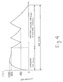
- the 75Wt%Co-25Wt%Fe (74At%Co-26At%Fe) alloy used in the second coil, as shown in Fig. 7, has an ⁇ / ⁇ transformation point in the vicinity of 800°C. Therefore, due to heating of the second coil during the engine starting operation and combustion in the engine, the temperature of the second coil will pass repeatedly through the ⁇ / ⁇ transformation point, resulting in a change in volume to create a strain on the second coil. This causes the second coil to be broken.
- the inventors of this application have proposed an arrangement wherein the first coil consists of a Fe-Cr-Al alloy and the second coil is made of a 92Wt%Co-8Wt%Fe alloy in view of the fact that they have a rate of change in resistance which is smaller than that of the75Wt%Co-25Wt%Fe alloy, but greater than that of Fe or Ni commonly used in the art, and do not have the ⁇ / ⁇ transformation point.
- Experiments were conducted with respect to a glow plug formed with the first coil and the second coil thus constructed. The experiments show that the glow plug provides quicker heating but remains indicating a short life (see the second comparative example C2 in Fig. 5).
- an electric resistance element which comprises a first resistance element having a given electric resistance and a second resistance element, connected in series with the first resistance element, having a resistance temperature coefficient positively higher than that of the first resistance element and providing a function of modifying a current to the first resistance element.
- the second resistance element is made of a Co-Fe alloy whose compositions fall in a range where a change in phase from a body-centered cubic lattice arrangement to a face-centered cubic lattice arrangement does not occur and a change in phase from a close-packed hexagonal lattice arrangement to the face-centered cubic lattice arrangement does not occur even when the second resistance element is subjected to a temperature change from a given room temperature to 1000°C.
- the first resistance element is welded at its end to an end of the second resistance element to form a connection therebetween which consists of part of material forming the first resistance element and part of the Co-Fe alloy forming the second resistance element, the material forming the first resistance element being so selected as to prevent compositions of the Co-Fe alloy in the connection from changing in phase from the body-centered cubic lattice arrangement to the face-centered cubic lattice arrangement and from the close-packed hexagonal lattice arrangement to the face-centered cubic lattice arrangement.
- the second resistance element contains 78At% to 95At% of Co and a remaining content of Fe.
- the first resistance element is made of a Ni-Cr alloy.
- a third resistance element may further be provided which connects between the first resistance element and the second resistance element in series therewith.
- the first resistance element may alternatively be made of a Fe-Cr-Al alloy.
- the third resistance element is made of Ni.
- the first resistance element has a Fe content of 68Wt% to 72Wt%.
- the Fe-Cr-Al alloy of the first resistance element has a Fe content of 68Wt% to 72Wt%.
- the Co-Fe alloy of the second coil has a Fe content of 7W% to 9Wt%.
- the volume ratio of the second to first resistance elements in a connection therebetween lies in a range from 1 : 0.15 to 1 : 0.25.
- a glow plug for an internal combustion engine which comprises a housing, a heater tube extending from an end of the housing, an insulating member arranged in the heater tube, and a resistance element.
- the resistance element includes at least two elements: a heating element and a regulating element connected in series with each other.
- the regulating element is electrically arranged upstream from the heating element.
- the regulating element assumes a positive resistance temperature coefficient higher than that of the heating element for regulating a current flowing to the heating element.
- the regulating element is made of a Co-Fe alloy whose compositions fall in a range where a change in phase from a body-centered cubic lattice arrangement to a face-centered cubic lattice arrangement does not occur and a change in phase from a close-packed hexagonal lattice arrangement to the face-centered cubic lattice arrangement does not occur even when the second resistance element is subjected to a temperature change from a given room temperature to 1000°C.
- the heating element is welded at its end to an end of the regulating element to form a connection therebetween which includes material of which the first resistance element is made and the Co-Fe alloy forming the regulating element.
- the material forming the heating element is so selected as to prevent compositions of the Co-Fe alloy in the connection from changing in phase from the body-centered cubic lattice arrangement to the face-centered cubic lattice arrangement and from the close-packed hexagonal lattice arrangement to the face-centered cubic lattice arrangement.
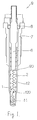
- a glow plug 9 according to the present invention which is commonly used in internal combustion engine such as a diesel engine to provide additional heat required for insuring quicker starting.
- the glow plug 9 includes generally a housing 7, a heater tube 90 partially inserted into the housing 7, and a heating coil 1 disposed within an insulating member 2 provided in the heating tube 90.
- the heating coil 1 is formed of a resistant filament including a first coil 11 serving as a heating element and a second coil 12 functioning as a regulating element for regulating a current flowing to the first coil.
- the first and second coils are connected in series by an arc welding process to form a welded connection 120.
- the first coil 11 is made of a Ni-Cr alloy which contains Ni of 80Wt% and Cr of 20Wt%.
- the second coil 12 is made of a Co-Fe alloy which contains Co of 92Wt% and Fe of 8Wt%.
- the Co-Fe alloy represents a rate of change in resistance (i.e., a resistance temperature coefficient) of about 13 in a range from the room temperature to 1000°C. This value, as can be seen in Fig. 8, is greater than those of Fe, Ni, and the first coil 11. It is desired that the Fe content of the second coil 12 fall in a range from 5At% to 22At%. When the Fe content is less than 5At%, it will cause the ⁇ / ⁇ transformation to occur, resulting in a change in volume.
- the ⁇ / ⁇ transformation may occur.
- the Co content of the second coil 12, as shown in Fig. 7 lie in a range from 78At% to 95At%.
- the welded connection 120 between the first and second coils 11 and 12 has a Co-Fe atomic percentage ratio of 91.6 : 8.4.
- the Fe content of the welded connection 120 which is less than or equal to 22Wt% is desirable. When more than 22Wt%, it will cause the welded connection 120 to assume the ⁇ / ⁇ transformation at an operational temperature of the glow plug 9.
- the heater tube 90 has a smaller diameter end portion which is bottomed. Outer and inner diameters of the heater tube 90 are so selected that the insulating member 2 around the first coil 11 is denser than that around the second coil 12.
- the insulating member 2 is made of insulating powder such as MgO.
- the heater tube 90 is formed of a heat-resistant alloy (e.g., SUS310S).
- the first coil 11 of the heating coil 1 is welded to the bottom of the heater tube 90, while the second coil 12 is welded to the end of a core shaft 6 which is disposed coaxially in the housing 7.
- the core shaft 6 is electrically connected at its end to a positive terminal of a battery (not shown).
- the housing 7 is so constructed as to mount the glow plug 9 in an engine head.
- the heater tube 90 is brazed to the housing 7.
- an O-ring 8 Arranged between the housing 7 and the core shaft 6 is an O-ring 8 made of fluororubber.
- the heating coil 1 When the heating coil 1 is energized, it will glow to heat the glow plug 9, providing additional heating required for insuring quicker starting of the engine.
- the heating coil 1, as mentioned above, includes the first and second coils 11 and 12.
- the second coil 12, as shown in Fig. 8, has the resistance temperature coefficient positively higher than that of the first resistance element, and is made of the Co-Fe alloy whose compositions, as shown in Fig. 7, fall in a range where a change in phase from a body-centered cubic lattice arrangement to a face-centered cubic lattice arrangement does not occur and a change in phase from a close-packed hexagonal lattice arrangement to the face-centered cubic lattice arrangement does not occur even when the second coil 12 is subjected to a temperature change from a given room temperature to 1000°C.
- connection 120 between the first and second coils 11 and 12 shows the Co-Fe atomic percentage ratio of 91.6 : 8.4 so that it lies, as is clear from Fig. 7, out of a range wherein changes in phase from the body-centered cubic lattice arrangement to the face-centered cubic lattice arrangement and from the close-packed hexagonal lattice arrangement to the face-centered cubic lattice arrangement occur. It will be appreciated that even when the temperature is changed rapidly, the connection 120 does not expand and contract so that it shows stable mechanical properties. Accordingly, the connection 120 is not broken even when the heating coil is heated rapidly many times so that the service life of the glow plug 9 is increased greatly.
- the O-ring 8 arranged between the core shaft 6 and the housing 7 serves to prevent oil and/or water from leaking into the housing 7. This avoids the heating coil 1 from being oxidized undesirably.
- the second coil 12 includes the Co-Fe alloy which assumes a relatively great rate of change in resistance of about 13 under the variation in temperature from the room temperature to 1000°C.
- the insulating member 2 is arranged to be denser around the first coil than that around the second coil 12. Therefore, the glow current controlling effect caused by a temperature rise of the second coil 12 is enhanced.
- the heater tube 90 includes the smaller diameter end portion in which the first coil is disposed and the large diameter middle portion in which the second coil is arranged so that the saturation temperature of the heating coil 1 is maintained safety and the temperature rising speed thereof is also improved greatly.
- FIG. 2 there is shown a second embodiment according to the present invention.
- the glow plug 9 of this embodiment is, as is clear from the drawing, different from the above first embodiment only in that the heating coil 1 includes first, second, and third coils 11, 12, and 13.
- the third coil is welded to form a connection 130 between the first and third coils 11 and 13 and a connection 230 between the third and second coils 13 and 12.
- Other arrangements are the same as in the first embodiment and explanation thereof in detail will be omitted here.
- the third coil 13 is made of Ni of 100Wt%.
- the first coil 11 is made of a 70Wt% Fe-25Wt% Cr-5Wt%Al alloy. It is desirable that the Fe content of the first coil 11 fall in a range from 68Wt% to 72Wt%. Thus, the connection 130 between the first and third coils 11 and 13 does not contain Co at all so that the ⁇ / ⁇ transformation does not occur.
- the second coil 12 is made of a 92Wt%Co-8Wt%Fe alloy. It is preferable that the Fe content of the second coil 12 range from 7Wt% to 9Wt%.
- connection 230 between the third and second coils 13 and 12 shows a Co-Fe atomic percentage ratio of 91.6 : 8.4, and thus the content of Fe is small so that the ⁇ / ⁇ transformation, as will be appreciated from Fig. 7, does not occur. Therefore, the service life of the glow plug is increased greatly without the connections 130 and 230 being broken.
- Fig. 3 shows an essential part of a third embodiment according to the invention.
- the heating coil 1 of this embodiment similar to the first embodiment, includes first and second coils 11 and 12 which are welded to form a connection 120 by a laser beam welding process.
- the connection 120 is constructed by adjusting the output and the focal depth of a laser beam to have a 1:0.2 ratio of the volume B of a fused portion 121 of the first coil 11 to the volume A of a fused portion 122 of the second coil 12.
- the first coil 11 is made of a 70Wt% Fe-25Wt% Cr-5Wt%Al alloy.
- the second coil 12 is also made of a 92Wt%Co-8Wt%Fe alloy.
- the connection 120 between the first and second coils 11 and 12 shows a Co-Fe atomic percentage ratio of 80 : 20.
- the B-A volume ratio of the connection 120 falls in a range from 0.15 to 0.25 and thus the content of Fe in the connection 120 is low. Therefore, the ⁇ / ⁇ transformation does not occur in the connection 120. The life of the glow plug is increased greatly without the connection 120 being broken.
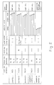
- Energizing cycle tests were performed with respect to the glow plugs constructed according to the above first, second, and third embodiments (examples 1,2, and 3).
- the glow plugs were, as shown in Fig. 4, applied with current for seventy minutes to be heated up to about 1000°C after which it is maintained at approximately 900°C. Subsequently, cooling and heating processes were conducted in an electric furnace three times in three minutes, and then cooled down to the room temperature. These were assumed to be one cycle and repeated continuously.
- the glow plug of the comparative example C1 includes a first coil made of a 70Wt%Fe-25Wt%Cr-15Wt%Al alloy and a second coil made of Ni. Other arrangements are substantially the same as the first embodiment.
- the glow plug of the comparative example C2 includes a first coil made of a 70Wt%Fe-25Wt%Cr-15Wt%Al alloy and a second coil made of a 92Wt%Co-8Wt%Fe alloy. Other arrangements are substantially the same as the comparative example.
- Fig. 5 is a table showing the results of the tests.
- the lifespans of the examples 1, 2, and 3 all exceed over 20000 cycles.
- the wire-breakage has occurred at the central portion of the first coil which is subjected to the intensest heat. Therefore, the glow plugs according to the invention may be used until their inherent service lives have expired.
- the comparative example C1 shows substantially the same results as in the first to third embodiments, however, the use of Ni having a ratio of change in resistance of 6 in the second coil gives rise to a problem in regard to quick heating when a statuary temperature is the same as the examples according to the present invention.
- the comparative example C2 exhibits an extremely shortened service life. There is a wire-breakage in a connection between the first and second coils.
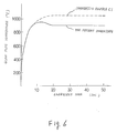
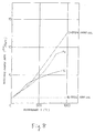
- Fig. 6 shows the relation between energizing time and temperature-rising speed in the glow plugs according to the first embodiment of the invention and the comparative example C1.
- the statuary temperature is maintained at 900°C which permits the glow plug to be energized constantly. This eliminates the need for reducing a voltage level applied to the glow plug after starting the engine, thereby eliminating the use of an after-glow resister, a sub-relay, and their attachment harnesses. Thus, the manufacturing costs are reduced greatly.
- the glow plug of the comparative example C1 shows a statuary temperature above 1000°C. It is thus, required to decrease the voltage applied to the glow plug after the engine starts.
- a glow plug for a diesel engine which includes generally a heating coil (1).
- the heating coil is provided with a first resistance element (11) and a second resistance element (12) connected in series with the first resistance element and having a resistance temperature coefficient positively higher than that of the first resistance element.
- the second resistance element (12) is made of a Co-Fe alloy whose compositions fall in a range where a change in phase from a body-centered cubic lattice arrangement to a face-centered cubic lattice arrangement does not occur and a change in phase from a close-packed hexagonal lattice arrangement to the face-centered cubic lattice arrangement does not occur even when the second resistance clement is subjected to a temperature change from a given room temperature to 1000°C.
- the first resistance element (11) is welded at its end to an end of the second resistance element (12) to form a connection therebetween which consists of-part of material forming the first resistance element and part of the Co-Fe alloy forming the second resistance element (12), the material forming the first resistance element (11) being so selected as to prevent compositions of the Co-Fe alloy in the connection from changing in phase from the body-centered cubic lattice arrangement to the face-centered cubic lattice arrangement and from the close-packed hexagonal lattice arrangement to the face-centered cubic lattice arrangement.
Landscapes
- Engineering & Computer Science (AREA)
- Chemical & Material Sciences (AREA)
- Combustion & Propulsion (AREA)
- Mechanical Engineering (AREA)
- General Engineering & Computer Science (AREA)
- Resistance Heating (AREA)
Applications Claiming Priority (3)
| Application Number | Priority Date | Filing Date | Title |
|---|---|---|---|
| JP5022011A JP2806195B2 (ja) | 1993-01-14 | 1993-01-14 | グロープラグ |
| JP22011/93 | 1993-01-14 | ||
| JP2201193 | 1993-01-14 |
Publications (4)
| Publication Number | Publication Date |
|---|---|
| EP0607872A2 true EP0607872A2 (de) | 1994-07-27 |
| EP0607872A3 EP0607872A3 (de) | 1995-04-19 |
| EP0607872B1 EP0607872B1 (de) | 1997-05-07 |
| EP0607872B2 EP0607872B2 (de) | 2002-03-20 |
Family
ID=12071065
Family Applications (1)
| Application Number | Title | Priority Date | Filing Date |
|---|---|---|---|
| EP94100446A Expired - Lifetime EP0607872B2 (de) | 1993-01-14 | 1994-01-13 | Glühkerze für Dieselmotoren |
Country Status (3)
| Country | Link |
|---|---|
| EP (1) | EP0607872B2 (de) |
| JP (1) | JP2806195B2 (de) |
| DE (1) | DE69402992T3 (de) |
Cited By (5)
| Publication number | Priority date | Publication date | Assignee | Title |
|---|---|---|---|---|
| EP0749133A3 (de) * | 1995-04-26 | 1997-10-29 | Vacuumschmelze Gmbh | Material für die Regelwendel einer Glühstiftkerze |
| US6037568A (en) * | 1996-01-18 | 2000-03-14 | Jidosha Kiki Co., Ltd. | Glow plug for diesel engine with ptc control element disposed in small-diameter sheath section and connected to the distal end thereof |
| EP1102007A3 (de) * | 1999-11-18 | 2005-08-31 | Denso Corporation | Glühkerze |
| EP1213540A3 (de) * | 2000-12-05 | 2006-06-07 | Vacuumschmelze GmbH & Co. KG | Glühstiftkerze für Brennkraftmaschinen |
| DE10014526B4 (de) * | 2000-03-23 | 2006-07-27 | NGK Spark Plug Co., Ltd., Nagoya | Selbstregelnde Schnellheizstabglühkerze |
Families Citing this family (5)
| Publication number | Priority date | Publication date | Assignee | Title |
|---|---|---|---|---|
| EP0354243B1 (de) * | 1987-07-24 | 1994-07-20 | JAPAN as represented by MINISTER OF INTERNATIONAL TRADE AND INDUSTRY | nerfahren zur Konzentrierung und Reinigung von Alkohol. |
| DE10041289B4 (de) * | 2000-08-22 | 2005-05-04 | Beru Ag | Glühkerze |
| JP6080578B2 (ja) * | 2013-02-06 | 2017-02-15 | 日本特殊陶業株式会社 | グロープラグ |
| JP6280853B2 (ja) * | 2013-10-15 | 2018-02-14 | 日本特殊陶業株式会社 | グロープラグ |
| JP6393124B2 (ja) * | 2013-11-15 | 2018-09-19 | 日本特殊陶業株式会社 | グロープラグ |
Family Cites Families (13)
| Publication number | Priority date | Publication date | Assignee | Title |
|---|---|---|---|---|
| CA1082949A (en) * | 1976-06-03 | 1980-08-05 | William F. Schilling | High-temperature austenitic alloys and articles utilizing the same |
| JPS6019404B2 (ja) * | 1980-10-22 | 1985-05-16 | 日本特殊陶業株式会社 | シ−ズグロ−プラグ |
| JPS62266323A (ja) * | 1986-05-13 | 1987-11-19 | Nippon Denso Co Ltd | デイ−ゼルエンジン用グロ−プラグ |
| JPS6420687A (en) * | 1987-07-15 | 1989-01-24 | Brother Ind Ltd | Drive circuit for semiconductor laser |
| JP2712211B2 (ja) * | 1987-12-21 | 1998-02-10 | 株式会社デンソー | シーズ型グロープラグ |
| GB2216952B (en) * | 1988-03-16 | 1991-10-02 | Wellman Automotive Products Li | Glow plugs |
| DE3822693A1 (de) † | 1988-07-05 | 1990-01-11 | Vacuumschmelze Gmbh | Widerstandselement fuer gluehkerzen |
| DE3825013A1 (de) * | 1988-07-22 | 1990-01-25 | Beru Werk Ruprecht Gmbh Co A | Gluehkerze |
| DE3923582C2 (de) * | 1988-07-22 | 1993-11-18 | Beru Werk Ruprecht Gmbh Co A | Glühkerze |
| DE3825012A1 (de) * | 1988-07-22 | 1990-01-25 | Beru Werk Ruprecht Gmbh Co A | Werkstoff fuer ein elektrisches widerstandselement mit positivem temperaturkoeffizienten |
| JPH0259372A (ja) * | 1988-08-24 | 1990-02-28 | Canon Inc | 画像記録装置 |
| DE3911506A1 (de) * | 1989-04-08 | 1990-10-11 | Bosch Gmbh Robert | Gluehstiftkerze |
| DE4010479A1 (de) * | 1990-03-31 | 1991-10-02 | Bosch Gmbh Robert | Gluehstiftkerze fuer brennkraftmaschinen |
-
1993
- 1993-01-14 JP JP5022011A patent/JP2806195B2/ja not_active Expired - Lifetime
-
1994
- 1994-01-13 DE DE1994602992 patent/DE69402992T3/de not_active Expired - Lifetime
- 1994-01-13 EP EP94100446A patent/EP0607872B2/de not_active Expired - Lifetime
Cited By (5)
| Publication number | Priority date | Publication date | Assignee | Title |
|---|---|---|---|---|
| EP0749133A3 (de) * | 1995-04-26 | 1997-10-29 | Vacuumschmelze Gmbh | Material für die Regelwendel einer Glühstiftkerze |
| US6037568A (en) * | 1996-01-18 | 2000-03-14 | Jidosha Kiki Co., Ltd. | Glow plug for diesel engine with ptc control element disposed in small-diameter sheath section and connected to the distal end thereof |
| EP1102007A3 (de) * | 1999-11-18 | 2005-08-31 | Denso Corporation | Glühkerze |
| DE10014526B4 (de) * | 2000-03-23 | 2006-07-27 | NGK Spark Plug Co., Ltd., Nagoya | Selbstregelnde Schnellheizstabglühkerze |
| EP1213540A3 (de) * | 2000-12-05 | 2006-06-07 | Vacuumschmelze GmbH & Co. KG | Glühstiftkerze für Brennkraftmaschinen |
Also Published As
| Publication number | Publication date |
|---|---|
| DE69402992D1 (de) | 1997-06-12 |
| JPH06213440A (ja) | 1994-08-02 |
| JP2806195B2 (ja) | 1998-09-30 |
| EP0607872B1 (de) | 1997-05-07 |
| DE69402992T3 (de) | 2002-08-08 |
| EP0607872A3 (de) | 1995-04-19 |
| DE69402992T2 (de) | 1997-11-13 |
| EP0607872B2 (de) | 2002-03-20 |
Similar Documents
| Publication | Publication Date | Title |
|---|---|---|
| US4636614A (en) | Self-control type glow plug | |
| US5218183A (en) | Self temperature control type glow plug | |
| US5319180A (en) | Glow plug with constant-structure cobalt-iron PTC resistor | |
| US6037568A (en) | Glow plug for diesel engine with ptc control element disposed in small-diameter sheath section and connected to the distal end thereof | |
| EP0607872B1 (de) | Glühkerze für Dieselmotoren | |
| US4549071A (en) | Glow plug for use in diesel engine | |
| JP2961124B2 (ja) | 正の温度係数を有する電気抵抗素子用の材料 | |
| JPH02110212A (ja) | グロープラグ | |
| US5039839A (en) | Diesel engine glow plug with self-temperature saturation characteristic and extended after-glow-time | |
| US5767485A (en) | Sheathed heater with a series-connected current regulating resistor comprised of cobalt-copper alloy | |
| US4650963A (en) | Ceramic glow plug | |
| US5521356A (en) | Glow plug with construction for minimizing heat transfer between interior pole and PTC regulating element | |
| US5132516A (en) | Glow plug having self-temperature control function | |
| US5206483A (en) | Temperature controlled glow plug having controlled saturation and afterglow characteristics | |
| EP0607592B1 (de) | Stabflammglühkerze | |
| JP2793004B2 (ja) | グロープラグ | |
| EP0441612A2 (de) | Kraftstoffeinspritzdüse | |
| JP3536261B2 (ja) | グロープラグ | |
| JP3736137B2 (ja) | グロープラグの製造方法 | |
| JP2004191040A (ja) | グロープラグ | |
| JPH08200676A (ja) | ディーゼルエンジン用グロープラグ | |
| EP0240650B1 (de) | Glühkerze mit zwei Glühwendeln für Dieselmotoren | |
| EP0602745A1 (de) | Glühkerze mit zwei Regelwendeln für Dieselmotoren | |
| JPH08250262A (ja) | セラミツクヒータ | |
| EP0902236A2 (de) | Glühkerze |
Legal Events
| Date | Code | Title | Description |
|---|---|---|---|
| PUAI | Public reference made under article 153(3) epc to a published international application that has entered the european phase |
Free format text: ORIGINAL CODE: 0009012 |
|
| AK | Designated contracting states |
Kind code of ref document: A2 Designated state(s): DE FR IT |
|
| PUAL | Search report despatched |
Free format text: ORIGINAL CODE: 0009013 |
|
| AK | Designated contracting states |
Kind code of ref document: A3 Designated state(s): DE FR IT |
|
| 17P | Request for examination filed |
Effective date: 19950529 |
|
| 17Q | First examination report despatched |
Effective date: 19951218 |
|
| GRAG | Despatch of communication of intention to grant |
Free format text: ORIGINAL CODE: EPIDOS AGRA |
|
| GRAH | Despatch of communication of intention to grant a patent |
Free format text: ORIGINAL CODE: EPIDOS IGRA |
|
| GRAH | Despatch of communication of intention to grant a patent |
Free format text: ORIGINAL CODE: EPIDOS IGRA |
|
| GRAA | (expected) grant |
Free format text: ORIGINAL CODE: 0009210 |
|
| AK | Designated contracting states |
Kind code of ref document: B1 Designated state(s): DE FR IT |
|
| RAP2 | Party data changed (patent owner data changed or rights of a patent transferred) |
Owner name: DENSO CORPORATION |
|
| REF | Corresponds to: |
Ref document number: 69402992 Country of ref document: DE Date of ref document: 19970612 |
|
| ET | Fr: translation filed | ||
| PLBQ | Unpublished change to opponent data |
Free format text: ORIGINAL CODE: EPIDOS OPPO |
|
| PLBI | Opposition filed |
Free format text: ORIGINAL CODE: 0009260 |
|
| PLBF | Reply of patent proprietor to notice(s) of opposition |
Free format text: ORIGINAL CODE: EPIDOS OBSO |
|
| 26 | Opposition filed |
Opponent name: ROBERT BOSCH GMBH Effective date: 19980205 |
|
| PLBF | Reply of patent proprietor to notice(s) of opposition |
Free format text: ORIGINAL CODE: EPIDOS OBSO |
|
| RDAH | Patent revoked |
Free format text: ORIGINAL CODE: EPIDOS REVO |
|
| APAC | Appeal dossier modified |
Free format text: ORIGINAL CODE: EPIDOS NOAPO |
|
| APAE | Appeal reference modified |
Free format text: ORIGINAL CODE: EPIDOS REFNO |
|
| APAC | Appeal dossier modified |
Free format text: ORIGINAL CODE: EPIDOS NOAPO |
|
| APAC | Appeal dossier modified |
Free format text: ORIGINAL CODE: EPIDOS NOAPO |
|
| PLAW | Interlocutory decision in opposition |
Free format text: ORIGINAL CODE: EPIDOS IDOP |
|
| PUAH | Patent maintained in amended form |
Free format text: ORIGINAL CODE: 0009272 |
|
| STAA | Information on the status of an ep patent application or granted ep patent |
Free format text: STATUS: PATENT MAINTAINED AS AMENDED |
|
| 27A | Patent maintained in amended form |
Effective date: 20020320 |
|
| AK | Designated contracting states |
Kind code of ref document: B2 Designated state(s): DE FR IT |
|
| ET3 | Fr: translation filed ** decision concerning opposition | ||
| APAH | Appeal reference modified |
Free format text: ORIGINAL CODE: EPIDOSCREFNO |
|
| PGFP | Annual fee paid to national office [announced via postgrant information from national office to epo] |
Ref country code: IT Payment date: 20100119 Year of fee payment: 17 Ref country code: FR Payment date: 20100208 Year of fee payment: 17 |
|
| REG | Reference to a national code |
Ref country code: FR Ref legal event code: ST Effective date: 20110930 |
|
| PG25 | Lapsed in a contracting state [announced via postgrant information from national office to epo] |
Ref country code: FR Free format text: LAPSE BECAUSE OF NON-PAYMENT OF DUE FEES Effective date: 20110131 |
|
| PG25 | Lapsed in a contracting state [announced via postgrant information from national office to epo] |
Ref country code: IT Free format text: LAPSE BECAUSE OF NON-PAYMENT OF DUE FEES Effective date: 20110113 |
|
| PGFP | Annual fee paid to national office [announced via postgrant information from national office to epo] |
Ref country code: DE Payment date: 20130109 Year of fee payment: 20 |
|
| REG | Reference to a national code |
Ref country code: DE Ref legal event code: R071 Ref document number: 69402992 Country of ref document: DE |
|
| PG25 | Lapsed in a contracting state [announced via postgrant information from national office to epo] |
Ref country code: DE Free format text: LAPSE BECAUSE OF EXPIRATION OF PROTECTION Effective date: 20140114 |