EP0607920A2 - Elektrischer Verbinder für Stromversorgungs- und Signalkontakte - Google Patents
Elektrischer Verbinder für Stromversorgungs- und Signalkontakte Download PDFInfo
- Publication number
- EP0607920A2 EP0607920A2 EP94100651A EP94100651A EP0607920A2 EP 0607920 A2 EP0607920 A2 EP 0607920A2 EP 94100651 A EP94100651 A EP 94100651A EP 94100651 A EP94100651 A EP 94100651A EP 0607920 A2 EP0607920 A2 EP 0607920A2
- Authority
- EP
- European Patent Office
- Prior art keywords
- divider
- signal contacts
- electrical connector
- contact
- fingers
- Prior art date
- Legal status (The legal status is an assumption and is not a legal conclusion. Google has not performed a legal analysis and makes no representation as to the accuracy of the status listed.)
- Granted
Links
- 238000005192 partition Methods 0.000 description 5
- 239000004020 conductor Substances 0.000 description 4
- 230000005540 biological transmission Effects 0.000 description 2
- 238000009413 insulation Methods 0.000 description 2
- 230000013011 mating Effects 0.000 description 2
- 239000002184 metal Substances 0.000 description 2
- 238000005452 bending Methods 0.000 description 1
- 238000010276 construction Methods 0.000 description 1
- 230000001419 dependent effect Effects 0.000 description 1
- 238000012986 modification Methods 0.000 description 1
- 230000004048 modification Effects 0.000 description 1
- 230000000284 resting effect Effects 0.000 description 1
Images




Classifications
-
- H—ELECTRICITY
- H01—ELECTRIC ELEMENTS
- H01R—ELECTRICALLY-CONDUCTIVE CONNECTIONS; STRUCTURAL ASSOCIATIONS OF A PLURALITY OF MUTUALLY-INSULATED ELECTRICAL CONNECTING ELEMENTS; COUPLING DEVICES; CURRENT COLLECTORS
- H01R12/00—Structural associations of a plurality of mutually-insulated electrical connecting elements, specially adapted for printed circuits, e.g. printed circuit boards [PCB], flat or ribbon cables, or like generally planar structures, e.g. terminal strips, terminal blocks; Coupling devices specially adapted for printed circuits, flat or ribbon cables, or like generally planar structures; Terminals specially adapted for contact with, or insertion into, printed circuits, flat or ribbon cables, or like generally planar structures
- H01R12/70—Coupling devices
- H01R12/71—Coupling devices for rigid printing circuits or like structures
- H01R12/72—Coupling devices for rigid printing circuits or like structures coupling with the edge of the rigid printed circuits or like structures
- H01R12/722—Coupling devices for rigid printing circuits or like structures coupling with the edge of the rigid printed circuits or like structures coupling devices mounted on the edge of the printed circuits
- H01R12/725—Coupling devices for rigid printing circuits or like structures coupling with the edge of the rigid printed circuits or like structures coupling devices mounted on the edge of the printed circuits containing contact members presenting a contact carrying strip, e.g. edge-like strip
-
- H—ELECTRICITY
- H01—ELECTRIC ELEMENTS
- H01R—ELECTRICALLY-CONDUCTIVE CONNECTIONS; STRUCTURAL ASSOCIATIONS OF A PLURALITY OF MUTUALLY-INSULATED ELECTRICAL CONNECTING ELEMENTS; COUPLING DEVICES; CURRENT COLLECTORS
- H01R13/00—Details of coupling devices of the kinds covered by groups H01R12/70 or H01R24/00 - H01R33/00
- H01R13/02—Contact members
- H01R13/26—Pin or blade contacts for sliding co-operation on one side only
-
- H—ELECTRICITY
- H01—ELECTRIC ELEMENTS
- H01R—ELECTRICALLY-CONDUCTIVE CONNECTIONS; STRUCTURAL ASSOCIATIONS OF A PLURALITY OF MUTUALLY-INSULATED ELECTRICAL CONNECTING ELEMENTS; COUPLING DEVICES; CURRENT COLLECTORS
- H01R13/00—Details of coupling devices of the kinds covered by groups H01R12/70 or H01R24/00 - H01R33/00
- H01R13/648—Protective earth or shield arrangements on coupling devices, e.g. anti-static shielding
- H01R13/6485—Electrostatic discharge protection
-
- H—ELECTRICITY
- H01—ELECTRIC ELEMENTS
- H01R—ELECTRICALLY-CONDUCTIVE CONNECTIONS; STRUCTURAL ASSOCIATIONS OF A PLURALITY OF MUTUALLY-INSULATED ELECTRICAL CONNECTING ELEMENTS; COUPLING DEVICES; CURRENT COLLECTORS
- H01R13/00—Details of coupling devices of the kinds covered by groups H01R12/70 or H01R24/00 - H01R33/00
- H01R13/648—Protective earth or shield arrangements on coupling devices, e.g. anti-static shielding
- H01R13/658—High frequency shielding arrangements, e.g. against EMI [Electro-Magnetic Interference] or EMP [Electro-Magnetic Pulse]
-
- H—ELECTRICITY
- H01—ELECTRIC ELEMENTS
- H01R—ELECTRICALLY-CONDUCTIVE CONNECTIONS; STRUCTURAL ASSOCIATIONS OF A PLURALITY OF MUTUALLY-INSULATED ELECTRICAL CONNECTING ELEMENTS; COUPLING DEVICES; CURRENT COLLECTORS
- H01R12/00—Structural associations of a plurality of mutually-insulated electrical connecting elements, specially adapted for printed circuits, e.g. printed circuit boards [PCB], flat or ribbon cables, or like generally planar structures, e.g. terminal strips, terminal blocks; Coupling devices specially adapted for printed circuits, flat or ribbon cables, or like generally planar structures; Terminals specially adapted for contact with, or insertion into, printed circuits, flat or ribbon cables, or like generally planar structures
- H01R12/70—Coupling devices
- H01R12/71—Coupling devices for rigid printing circuits or like structures
- H01R12/712—Coupling devices for rigid printing circuits or like structures co-operating with the surface of the printed circuit or with a coupling device exclusively provided on the surface of the printed circuit
- H01R12/716—Coupling device provided on the PCB
-
- H—ELECTRICITY
- H01—ELECTRIC ELEMENTS
- H01R—ELECTRICALLY-CONDUCTIVE CONNECTIONS; STRUCTURAL ASSOCIATIONS OF A PLURALITY OF MUTUALLY-INSULATED ELECTRICAL CONNECTING ELEMENTS; COUPLING DEVICES; CURRENT COLLECTORS
- H01R12/00—Structural associations of a plurality of mutually-insulated electrical connecting elements, specially adapted for printed circuits, e.g. printed circuit boards [PCB], flat or ribbon cables, or like generally planar structures, e.g. terminal strips, terminal blocks; Coupling devices specially adapted for printed circuits, flat or ribbon cables, or like generally planar structures; Terminals specially adapted for contact with, or insertion into, printed circuits, flat or ribbon cables, or like generally planar structures
- H01R12/70—Coupling devices
- H01R12/71—Coupling devices for rigid printing circuits or like structures
- H01R12/72—Coupling devices for rigid printing circuits or like structures coupling with the edge of the rigid printed circuits or like structures
- H01R12/722—Coupling devices for rigid printing circuits or like structures coupling with the edge of the rigid printed circuits or like structures coupling devices mounted on the edge of the printed circuits
- H01R12/724—Coupling devices for rigid printing circuits or like structures coupling with the edge of the rigid printed circuits or like structures coupling devices mounted on the edge of the printed circuits containing contact members forming a right angle
-
- H—ELECTRICITY
- H01—ELECTRIC ELEMENTS
- H01R—ELECTRICALLY-CONDUCTIVE CONNECTIONS; STRUCTURAL ASSOCIATIONS OF A PLURALITY OF MUTUALLY-INSULATED ELECTRICAL CONNECTING ELEMENTS; COUPLING DEVICES; CURRENT COLLECTORS
- H01R13/00—Details of coupling devices of the kinds covered by groups H01R12/70 or H01R24/00 - H01R33/00
- H01R13/66—Structural association with built-in electrical component
-
- H—ELECTRICITY
- H01—ELECTRIC ELEMENTS
- H01R—ELECTRICALLY-CONDUCTIVE CONNECTIONS; STRUCTURAL ASSOCIATIONS OF A PLURALITY OF MUTUALLY-INSULATED ELECTRICAL CONNECTING ELEMENTS; COUPLING DEVICES; CURRENT COLLECTORS
- H01R2107/00—Four or more poles
-
- H—ELECTRICITY
- H01—ELECTRIC ELEMENTS
- H01R—ELECTRICALLY-CONDUCTIVE CONNECTIONS; STRUCTURAL ASSOCIATIONS OF A PLURALITY OF MUTUALLY-INSULATED ELECTRICAL CONNECTING ELEMENTS; COUPLING DEVICES; CURRENT COLLECTORS
- H01R24/00—Two-part coupling devices, or either of their cooperating parts, characterised by their overall structure
- H01R24/60—Contacts spaced along planar side wall transverse to longitudinal axis of engagement
Definitions
- the present invention relates to an electrical connector having electrical contacts for transmitting electrical power and electrical signals in a single connector.
- the present invention relates to an electrical connector according to the preamble of claim 1.
- An electrical connector known from US-A-3,760,335, comprises, an insulating housing and conductive signal contacts.
- the contacts are grouped in pairs, with an insulative divider of the housing separating one contact of the pair from the other contact of the pair. Multiple pairs of the contacts are distributed along the insulative divider.
- the pairs of contacts are especially suitable for connection to twisted pair wires used in the communications industry for data and voice transmission. Each pair of the twisted pair wires are connected to one pair of the contacts.
- the signal contacts known from US-A-3,760,335, are suitable for transmitting electrical signals of relatively low power, but are of inadequate mass and surface area to dissipate heat from electrical power transmission.
- a single connector for both signal contacts and at least one power contact is suitable for connection to a circuit board.
- an electrical connector comprises both signal contacts and at least one power contact in the same insulative housing.
- An electrical connector according to the invention is suitable for connection to twisted pair wires and to conductors of an electrical power cable.
- an electrical connector is suitable for connection to both signal and power conductors routed on a circuit board.
- An electrical connector comprises an insulative housing, multiple pairs of conductive signal contacts distributed along an insulative divider within the housing and adapted to be connected to respective pairs of signal wires, at least one conductive power contact having a pair of contact fingers on opposite sides of the divider, the contact fingers having a surface area sufficiently broad to radiate heat from electrical power dissipation.
- the invention provides an electrical connector as defined in claim 1. Preferred embodiments are define in the dependent claims.
- An advantage of the present invention is an electrical connector that includes signal and power contacts. Another advantage of the invention is the contact fingers of the power contacts have a surface area sufficiently broad to radiate heat from electrical power dissipation.
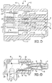
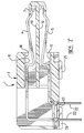
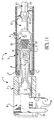
- each of the plug connector and receptacle connector of an electrical connector 1 comprises an insulative housing 2 , multiple pairs 3 of conductive signal contacts 4 , 5 , accompanied by at least one power contact 6 , in the housing 2.
- the pairs 3 of the signal contacts 4, 5 are distributed along an insulative divider 7 in an interior 8 of the housing 2.
- the signal contacts 4, 5 of each pair 3 are on opposite sides of the divider 7 that separates the signal contacts 4, 5 of each pair 3.
- the signal contacts 4, 5 are in rows, and are parallel to one another.
- a pair of contact fingers 9 on the power contact 6 are on opposite sides of the divider 7, and extend parallel to the signal contacts 4, 5.
- each of the fingers 9 is larger than that of each of the signal contacts 4, 5, and is sufficiently broad to radiate heat from electrical power dissipation.
- each of the fingers 9 is of greater mass than each of the signal contacts 4, 5 to carry electrical current. When electrical current is transmitted by the power contact 6, dissipation of electrical power generates heat. The heat is radiated from the surface area of the power contact 6. A larger surface area and a higher mass of the power contact 6 will limit the temperature attained by the power contact 6.
- the divider 7 bridges between, and is joined to side walls 10 , 11 of the housing 2.
- the divider 7 extends from a front mating end 12 of the housing 2 and rearwardly in the interior 8 of the housing 2.
- Spaced apart partitions 13 in the interior 8 bridge between the divider 7 and a top wall 14 of the housing 2, and between the divider 7 and a bottom wall 15 of the housing 2.
- the partitions 13 join the divider 7 and the top and bottom walls 14, 15.
- the walls 14, 15 bridge between and join the side walls 10, 11 to form the exterior of the housing 2.
- Contact receiving cavities 16 in the housing 2 are defined between the partitions 13 and extend behind the divider 7 to receive the signal contacts 4, 5.
- the fingers 9 are connected to a body portion 17 having a surface area sufficiently broad to radiate heat from electrical power dissipation.
- Each of the contact receiving cavities 16 is smaller than the pocket 18.
- the power contact 6 can be inserted in the housing 2 unmistakenly in the pocket 18 that is larger than each of the smaller, contact receiving cavities 16 that is smaller than the body portion 17.
- the divider 7 extends forwardly of the partitions 13, and is provided with a series of grooves 19 on its opposite sides aligned with the contact receiving passages. The grooves 19 receive the signal contacts 4, 5 and the contact fingers 9.
- the grooves 19 that receive the contact fingers 9 are larger than the grooves 19 that receive the signal contacts 4, 5. Projecting lances 20 on each signal contact 4, 5 and on the power contact 6 impinge against walls 21 of the housing 2, and resist withdrawal of the contacts 4, 5 and 6 from the grooves 19.
- Each of the signal contacts 4, 5 and the power contact 6 is of unitary construction, stamped and formed from a strip of metal.
- the divider 7 is spaced apart from the top and bottom walls 14, 15 of the housing 2.
- the grooves 19 face toward the top and bottom walls 14, 15.
- the pairs 3 of signal contacts 4, 5 are adapted to be connected to a circuit board, not shown.
- An electrical termination 22 in the form of a post extends laterally downward from each of the signal contacts 4, 5 for connection to a circuit board, not shown, and more particularly, to a plated aperture, not shown of the circuit board.
- the terminations 22 extend laterally downward by bending the signal contacts 4, 5 along their lengths, the signal contact 4 being longer in length than the signal contact 5.
- the body portion 17 has a thickness that is the same thickness as each of the contact fingers 9.
- the fingers 9 are bent to extend outward from the body portion 17 such that the thickness of the body portion 17 is in a plane perpendicular to a plane of thickness of each of the contact fingers 9.
- a termination 22 in the form of a pair of posts extend laterally downward of each body portion 17 for connection to a circuit board, not shown, and more particularly, for connection in plated apertures, not shown, of the circuit board.
- Each of the terminations 22 is larger in surface area and mass than that of each of the terminations 22 on the signal contacts 4, 5, thereby to conduct electrical current, and to radiate heat resulting from dissipation of electrical power.
- the terminations 22 are on the signal contacts 4, 5 where they emerge from a rear of the divider 7.
- the terminations 22 are on the power contact 6 where it emerges from a rear of the divider 7.
- a series of slots 23 in the bottom wall 15 of the housing 2 have open ends communicating with a rear end 24 of the bottom wall 15.
- the terminations 22 project through the slots 23, with the terminations 22 of each pair 3 of the contacts 4, 5 being spaced apart along the same slot 23.
- the bottom wall 15 of the housing 2 provides a base from which knob shaped feet 25 extend for resting against a circuit board, not shown.
- the cable connector 1 is adapted for mated connection with the version of the connector 1, Figures 2-7, for mounting on a circuit board, not shown.
- the divider 7 of the cable connector 1 is bifurcated by a passage 26 at the front mating end 12 for receiving the divider 7 of the version of the connector 1 for mounting on a circuit board, not shown.
- the grooves 19 face toward the passage 26, such that the contacts 4, 5 on opposite sides of the divider 7 face toward the passage 26.
- the pairs 3 of signal contacts 4, 5 are adapted to be connected to respective pairs 3 of signal wires 27 of a single electrical cable, not shown, or of multiple electrical cables, not shown.
- the signal wires 27 can be a twisted pair of signal wires 27.
- each of the signal contacts further comprises a termination 22 having arms 28 that extend outward laterally of each other, the arms being bendable into an open barrel configuration to encircle and connect with the signal wire 27.
- Another set of arms 29 extend laterally of each other, the arms 29 being bendable into an open barrel configuration to encircle and connect with insulation 30 , Figure 8, encircling the signal wire 27.
- the contact fingers 9 extend from a connection to an electrical power transmitting wire 31 larger in diameter than each of the signal wires 27.
- the wire 31 may comprise an electrical power cable.
- the body portion 17 comprises a termination 22 having sets of arms 32 , 33 that extend outward laterally of each other, the arms 32 being bendable into an open barrel configuration to encircle and connect with the electrical power transmitting wire 31.
- the wire 31 is larger in diameter than each of the signal wires 27 to carry electrical current.
- the signal wires 27 are smaller in diameter, as they are required to transmit electrical signals of which the voltage, not the electrical power, is of paramount importance.
- the set of arms 33 extend laterally of each other, and are bendable into an open barrel configuration to encircle and connect with insulation 34 encircling the wire 31.
- An electrical connector 1 comprises both signal contacts 4, 5 and at least one power contact 6 in the same insulative housing 2.
- An electrical connector 1 is suitable for connection to twisted pair wires 4, 5 and to a conductor 31 of an electrical power cable.
- an electrical connector 1 is suitable for connection to both signal and power conductors routed on a circuit board.
- metal shield members can be mounted on the dielectric housings of the matable connectors to shield the electrical connections between the electrical contacts when the connectors are matably connected together.
Landscapes
- Coupling Device And Connection With Printed Circuit (AREA)
- Details Of Connecting Devices For Male And Female Coupling (AREA)
- Connector Housings Or Holding Contact Members (AREA)
Applications Claiming Priority (2)
| Application Number | Priority Date | Filing Date | Title |
|---|---|---|---|
| US5690 | 1993-01-19 | ||
| US08/005,690 US5295843A (en) | 1993-01-19 | 1993-01-19 | Electrical connector for power and signal contacts |
Publications (3)
| Publication Number | Publication Date |
|---|---|
| EP0607920A2 true EP0607920A2 (de) | 1994-07-27 |
| EP0607920A3 EP0607920A3 (en) | 1996-01-31 |
| EP0607920B1 EP0607920B1 (de) | 1998-11-11 |
Family
ID=21717209
Family Applications (1)
| Application Number | Title | Priority Date | Filing Date |
|---|---|---|---|
| EP94100651A Expired - Lifetime EP0607920B1 (de) | 1993-01-19 | 1994-01-18 | Elektrischer Verbinder für Stromversorgungs- und Signalkontakte |
Country Status (7)
| Country | Link |
|---|---|
| US (3) | US5295843A (de) |
| EP (1) | EP0607920B1 (de) |
| JP (1) | JPH06231821A (de) |
| KR (1) | KR100248680B1 (de) |
| CN (1) | CN1074592C (de) |
| DE (1) | DE69414428T2 (de) |
| TW (1) | TW252229B (de) |
Cited By (1)
| Publication number | Priority date | Publication date | Assignee | Title |
|---|---|---|---|---|
| DE29504865U1 (de) * | 1995-03-22 | 1995-05-11 | Siemens AG, 80333 München | Anschlußadapter für Installationsgeräte und Busgeräte |
Families Citing this family (161)
| Publication number | Priority date | Publication date | Assignee | Title |
|---|---|---|---|---|
| US5639265A (en) * | 1994-07-30 | 1997-06-17 | Mitsumi Electric Co., Ltd. | Electric connector |
| US5793617A (en) * | 1995-02-23 | 1998-08-11 | Intel Corporation | Shorter compact expansion card to replace an Extended Industry Standard Architecture (EISA) card |
| DE69602669T2 (de) * | 1995-03-27 | 1999-11-11 | The Whitaker Corp., Wilmington | Elektrischer Verbinder |
| US5641308A (en) * | 1995-04-28 | 1997-06-24 | Molex Incorporated | Electrical connector |
| US5643013A (en) * | 1995-05-24 | 1997-07-01 | The Whitaker Corporation | Electrical connector |
| US5700164A (en) * | 1995-06-16 | 1997-12-23 | The Whitaker Corporation | Electrical connector with shield |
| JP3095349B2 (ja) * | 1996-03-21 | 2000-10-03 | ヒロセ電機株式会社 | 電気コネクタ |
| US6116956A (en) * | 1996-04-19 | 2000-09-12 | Wu; Kun-Tsan | Electrical connector for a power supply |
| CA2252611A1 (en) * | 1996-04-22 | 1997-10-30 | Siemens Aktiengesellschaft | Plug-in connector with contact surface protection in the plug-in opening area |
| JPH09320693A (ja) * | 1996-05-24 | 1997-12-12 | Amp Japan Ltd | 電気コネクタ組立体、その組立体に使用される電気コネクタ及びその電気コネクタに使用されるコンタクト |
| TW313343U (en) * | 1997-01-17 | 1997-08-11 | Su-Lan Yanglee | Electrical connector device |
| JP3843402B2 (ja) * | 1997-03-07 | 2006-11-08 | モレックス インコーポレーテッド | 電気コネクタの製造法 |
| US5901038A (en) * | 1997-03-17 | 1999-05-04 | Cheng; Wing Ling | Power supply system for high density printed circuit boards |
| JP3640759B2 (ja) * | 1997-04-09 | 2005-04-20 | ケル株式会社 | コネクタ |
| US5993263A (en) * | 1997-08-15 | 1999-11-30 | Molex Incorporated | Reduced mating force electrical connector |
| JPH11185897A (ja) * | 1997-12-17 | 1999-07-09 | Jst Mfg Co Ltd | 薄型カートリッジ用コネクタ |
| US6319075B1 (en) * | 1998-04-17 | 2001-11-20 | Fci Americas Technology, Inc. | Power connector |
| US7314377B2 (en) * | 1998-04-17 | 2008-01-01 | Fci Americas Technology, Inc. | Electrical power connector |
| US20020098743A1 (en) * | 1998-04-17 | 2002-07-25 | Schell Mark S. | Power connector |
| EP1605550B1 (de) * | 1998-04-17 | 2007-10-17 | Fci | Elektrische Anschlussblöcke mit Signal- und Leistungseigenschaften |
| TW405764U (en) | 1998-10-19 | 2000-09-11 | Molex Inc | Connector supporting device |
| US6166892A (en) * | 1998-12-18 | 2000-12-26 | Hon Hai Precision Ind. Co., Ltd. | Connector with built-in resettable power regulation |
| US6257903B1 (en) * | 1999-02-05 | 2001-07-10 | Visteon Global Technologies, Inc. | Self-docking electrical connector |
| US6247948B1 (en) * | 1999-02-08 | 2001-06-19 | The Whitaker Corporation | Electrical connector and panel assembly |
| WO2000077887A1 (en) * | 1999-06-16 | 2000-12-21 | Fci 's-Hertogenbosch B.V. | Connector, method for manufacturing such a connector and contact element for a connector |
| NL1012363C2 (nl) * | 1999-06-16 | 2000-12-19 | Berg Electronics Mfg | Connectors. |
| DE19939580C2 (de) * | 1999-08-20 | 2003-11-27 | Tyco Electronics Logistics Ag | Elektrischer Steckverbinder |
| US6270379B1 (en) * | 1999-09-14 | 2001-08-07 | Hon Hai Precision Ind. Co., Ltd. | Connector with securely retained contacts |
| US6217347B1 (en) | 1999-10-01 | 2001-04-17 | Berg Technology, Inc. | Electrical connector having multiple arrays of contacts with co-linear mounting points |
| SG101926A1 (en) * | 1999-11-12 | 2004-02-27 | Molex Inc | Power connector |
| US6257929B1 (en) * | 1999-12-27 | 2001-07-10 | Hon Hai Precision Ind. Co., Ltd. | Shielded connector assembly |
| JP2001223057A (ja) * | 2000-02-09 | 2001-08-17 | Hirose Electric Co Ltd | 電気コネクタ |
| US6290514B1 (en) * | 2000-04-13 | 2001-09-18 | Hon Hai Precision Ind. Co., Ltd. | Low-inductance low-resistance electrical connector |
| JP2002175856A (ja) * | 2000-10-13 | 2002-06-21 | Hewlett Packard Co <Hp> | 2つの物体を電気的に接続するための方法および装置 |
| US6592381B2 (en) | 2001-01-25 | 2003-07-15 | Teradyne, Inc. | Waferized power connector |
| US6383023B1 (en) * | 2001-01-26 | 2002-05-07 | Hon Hai Precision, Inc., Co., Ltd. | Electrical connector with power contacts positioned at lateral ends without increasing dimension thereof |
| JP2002298968A (ja) * | 2001-03-30 | 2002-10-11 | Mitsumi Electric Co Ltd | コネクタ |
| US6619993B2 (en) * | 2001-06-01 | 2003-09-16 | Robert Jayne | DSX jack connection system |
| JP4841756B2 (ja) * | 2001-06-08 | 2011-12-21 | 日本圧着端子製造株式会社 | コンタクトとこれを装着した電気コネクタ |
| US6835091B2 (en) * | 2001-07-06 | 2004-12-28 | Fci Americas Technology, Inc. | Universal serial bus electrical connector |
| US7044752B2 (en) * | 2002-05-24 | 2006-05-16 | Fci Americas Technology, Inc. | Receptacle |
| US6942525B2 (en) | 2002-05-24 | 2005-09-13 | Fci Americas Technology, Inc. | Plug |
| CN101051719A (zh) * | 2002-05-24 | 2007-10-10 | Fci公司 | 改进的插头 |
| US6663428B1 (en) * | 2002-08-09 | 2003-12-16 | Hon Hai Precision Ind. Co., Ltd. | Electrical connector with improved grounding terminal arrangement |
| US6663406B1 (en) * | 2002-09-17 | 2003-12-16 | Hon Hai Precision Ind. Co., Ltd. | Slanted electrical connector having board lock |
| US6890221B2 (en) * | 2003-01-27 | 2005-05-10 | Fci Americas Technology, Inc. | Power connector with male and female contacts |
| US6780027B2 (en) | 2003-01-28 | 2004-08-24 | Fci Americas Technology, Inc. | Power connector with vertical male AC power contacts |
| US20040147169A1 (en) | 2003-01-28 | 2004-07-29 | Allison Jeffrey W. | Power connector with safety feature |
| TW568460U (en) * | 2003-04-11 | 2003-12-21 | Surtec Ind Inc | Signal connector device |
| US6758685B1 (en) * | 2003-04-11 | 2004-07-06 | Compal Electronics, Inc. | Serial advanced technology attachment connector |
| TW200501521A (en) * | 2003-04-16 | 2005-01-01 | J S T Mfg Co Ltd | Electric coupler and housing of plug-type connector |
| US6848950B2 (en) * | 2003-05-23 | 2005-02-01 | Fci Americas Technology, Inc. | Multi-interface power contact and electrical connector including same |
| US6881102B2 (en) * | 2003-06-13 | 2005-04-19 | Tyco Electronics Corporation | Terminal locking mechanism for hybrid electrical connector |
| US6872100B2 (en) * | 2003-06-13 | 2005-03-29 | Tyco Electronics Corporation | Terminal locking mechanism for hybrid electrical connector |
| ATE498219T1 (de) * | 2003-07-28 | 2011-02-15 | Sandisk Secure Content Solutions Inc | Elektrischer verbinder |
| US7049514B2 (en) * | 2003-09-30 | 2006-05-23 | Rockwell Automation Technologies, Inc. | Rail system for distributing power and data signals |
| US6939181B2 (en) * | 2003-10-31 | 2005-09-06 | Medtronic, Inc. | Assembly and method for connecting electrical medical components |
| CN2682660Y (zh) * | 2003-12-06 | 2005-03-02 | 富士康(昆山)电脑接插件有限公司 | 电连接器 |
| CN2674672Y (zh) * | 2003-12-06 | 2005-01-26 | 富士康(昆山)电脑接插件有限公司 | 电源连接器 |
| US7458839B2 (en) * | 2006-02-21 | 2008-12-02 | Fci Americas Technology, Inc. | Electrical connectors having power contacts with alignment and/or restraining features |
| CN101882718B (zh) | 2003-12-31 | 2012-11-21 | Fci公司 | 电源触头及包括电源触头的连接器 |
| US7094089B2 (en) * | 2004-03-12 | 2006-08-22 | Apple Computer, Inc. | DC connector assembly |
| CN2728007Y (zh) * | 2004-08-05 | 2005-09-21 | 富士康(昆山)电脑接插件有限公司 | 电连接器 |
| US7525216B2 (en) * | 2005-01-07 | 2009-04-28 | Apple Inc. | Portable power source to provide power to an electronic device via an interface |
| US20060154530A1 (en) * | 2005-01-07 | 2006-07-13 | Novotney Donald J | Connector system |
| US7384289B2 (en) | 2005-01-31 | 2008-06-10 | Fci Americas Technology, Inc. | Surface-mount connector |
| US7354282B2 (en) * | 2005-06-15 | 2008-04-08 | Molex Incorporated | Electrical connector having blade terminals |
| US7589536B2 (en) | 2007-01-05 | 2009-09-15 | Apple Inc. | Systems and methods for determining the configuration of electronic connections |
| US7599191B2 (en) * | 2005-11-01 | 2009-10-06 | Avx Corporation | Electrochemical low ESR capacitor with connector |
| US7376215B2 (en) * | 2005-12-27 | 2008-05-20 | Honeywell International Inc. | Measurement of ash composition using scanning high voltage X-ray sensor |
| EP1977156A4 (de) * | 2006-01-04 | 2011-06-22 | Luxim Corp | Plasmaleuchte mit feldfokussierender antenne |
| DE102006008015B3 (de) * | 2006-02-21 | 2007-04-12 | Harting Electronics Gmbh & Co. Kg | Leiterplatten-Steckfortsatz |
| US7726982B2 (en) | 2006-06-15 | 2010-06-01 | Fci Americas Technology, Inc. | Electrical connectors with air-circulation features |
| US7594827B2 (en) * | 2006-11-17 | 2009-09-29 | Nintendo Co., Ltd. | Secure and/or lockable connecting arrangement for video game system |
| US7862367B2 (en) * | 2007-04-04 | 2011-01-04 | John Mezzalingua Associates, Inc. | Releasably engaging high definition multimedia interface plug |
| US8628345B2 (en) * | 2007-04-04 | 2014-01-14 | Ppc Broadband, Inc. | Releasably engaging high definition multimedia interface plug |
| US7857652B2 (en) * | 2007-04-04 | 2010-12-28 | John Mezzalingua Associates, Inc. | Releasably engaging high definition multimedia interface plug |
| US7892014B2 (en) * | 2007-04-04 | 2011-02-22 | John Mezzalingua Associates, Inc. | Releasably engaging high definition multimedia interface plug |
| US7641500B2 (en) | 2007-04-04 | 2010-01-05 | Fci Americas Technology, Inc. | Power cable connector system |
| US7476118B2 (en) * | 2007-04-04 | 2009-01-13 | John Mezzalingua Assoc., Inc. | Releasably engaging high definition multimedia interface plug |
| US7905731B2 (en) | 2007-05-21 | 2011-03-15 | Fci Americas Technology, Inc. | Electrical connector with stress-distribution features |
| US7762857B2 (en) * | 2007-10-01 | 2010-07-27 | Fci Americas Technology, Inc. | Power connectors with contact-retention features |
| US7785152B2 (en) * | 2008-04-22 | 2010-08-31 | Hon Hai Precision Ind. Co., Ltd | High density connector having two-leveled contact interface |
| US7976342B2 (en) * | 2008-06-04 | 2011-07-12 | Tyco Electronics Corporation | High density rectangular interconnect |
| USD589455S1 (en) * | 2008-06-11 | 2009-03-31 | Hon Hai Precision Ind. Co., Ltd. | Electronic adaptor |
| US8062051B2 (en) * | 2008-07-29 | 2011-11-22 | Fci Americas Technology Llc | Electrical communication system having latching and strain relief features |
| US7635280B1 (en) * | 2008-07-30 | 2009-12-22 | Apple Inc. | Type A USB receptacle with plug detection |
| JP5324173B2 (ja) * | 2008-09-25 | 2013-10-23 | 日本圧着端子製造株式会社 | コネクタ及びコネクタの製造方法 |
| US20100112859A1 (en) * | 2008-10-30 | 2010-05-06 | Olawsky Barry L | Shielded connector system |
| USD664096S1 (en) | 2009-01-16 | 2012-07-24 | Fci Americas Technology Llc | Vertical electrical connector |
| USD608293S1 (en) | 2009-01-16 | 2010-01-19 | Fci Americas Technology, Inc. | Vertical electrical connector |
| USD640637S1 (en) | 2009-01-16 | 2011-06-28 | Fci Americas Technology Llc | Vertical electrical connector |
| USD610548S1 (en) | 2009-01-16 | 2010-02-23 | Fci Americas Technology, Inc. | Right-angle electrical connector |
| USD606496S1 (en) | 2009-01-16 | 2009-12-22 | Fci Americas Technology, Inc. | Right-angle electrical connector |
| USD606497S1 (en) | 2009-01-16 | 2009-12-22 | Fci Americas Technology, Inc. | Vertical electrical connector |
| US8323049B2 (en) * | 2009-01-30 | 2012-12-04 | Fci Americas Technology Llc | Electrical connector having power contacts |
| USD619099S1 (en) | 2009-01-30 | 2010-07-06 | Fci Americas Technology, Inc. | Electrical connector |
| US8366485B2 (en) | 2009-03-19 | 2013-02-05 | Fci Americas Technology Llc | Electrical connector having ribbed ground plate |
| USD618181S1 (en) | 2009-04-03 | 2010-06-22 | Fci Americas Technology, Inc. | Asymmetrical electrical connector |
| USD618180S1 (en) | 2009-04-03 | 2010-06-22 | Fci Americas Technology, Inc. | Asymmetrical electrical connector |
| JP2010251319A (ja) | 2009-04-15 | 2010-11-04 | Chou Hsien Tsai | 双方向電気的連接が可能なソケット構造 |
| US8070526B2 (en) * | 2009-08-19 | 2011-12-06 | Hon Hai Precision Ind. Co., Ltd. | Electrical connector with improved terminals assembled to insulative housing from top to bottom |
| CN201656090U (zh) * | 2010-03-29 | 2010-11-24 | 美国莫列斯股份有限公司 | 电连接器 |
| CN201956490U (zh) * | 2010-05-21 | 2011-08-31 | 梁骞 | 一种可双面插接的usb插座与插头 |
| RU2544839C2 (ru) | 2010-05-28 | 2015-03-20 | Эппл Инк. | Соединитель с двойной ориентацией с внешними контактами |
| JP5066243B2 (ja) * | 2010-06-08 | 2012-11-07 | ヒロセ電機株式会社 | 電気コネクタ、およびツイストペアケーブルと電気コネクタとの接続方法 |
| US8931962B2 (en) | 2010-06-18 | 2015-01-13 | Apple Inc. | Dual orientation connector with side contacts |
| CN103004035A (zh) | 2010-06-21 | 2013-03-27 | 苹果公司 | 外部接触插塞连接器 |
| US8882524B2 (en) * | 2010-06-21 | 2014-11-11 | Apple Inc. | External contact plug connector |
| US10243284B2 (en) * | 2011-01-31 | 2019-03-26 | Amphenol Corporation | Multi-stage beam contacts |
| US8512081B2 (en) * | 2011-01-31 | 2013-08-20 | Amphenol Corporation | Multi-stage beam contacts |
| US8277258B1 (en) * | 2011-03-11 | 2012-10-02 | Cheng Uei Precision Industry Co., Ltd. | Electrical connector |
| US8727796B2 (en) * | 2011-08-12 | 2014-05-20 | Fci Americas Technology Llc | Power connector |
| US9293876B2 (en) | 2011-11-07 | 2016-03-22 | Apple Inc. | Techniques for configuring contacts of a connector |
| US8708745B2 (en) | 2011-11-07 | 2014-04-29 | Apple Inc. | Dual orientation electronic connector |
| US9112327B2 (en) | 2011-11-30 | 2015-08-18 | Apple Inc. | Audio/video connector for an electronic device |
| EP2792027A4 (de) * | 2011-12-14 | 2015-09-09 | Intel Corp | Verbinder mit skalierbarer rate für verbraucheranwendungen mit hoher bandbreite |
| US8591265B2 (en) * | 2012-01-05 | 2013-11-26 | Cheng Uei Precision Industry Co., Ltd. | Receptacle connector |
| EP2624034A1 (de) | 2012-01-31 | 2013-08-07 | Fci | Abbaubare optische Kupplungsvorrichtung |
| USD718253S1 (en) | 2012-04-13 | 2014-11-25 | Fci Americas Technology Llc | Electrical cable connector |
| USD727268S1 (en) | 2012-04-13 | 2015-04-21 | Fci Americas Technology Llc | Vertical electrical connector |
| US8944831B2 (en) | 2012-04-13 | 2015-02-03 | Fci Americas Technology Llc | Electrical connector having ribbed ground plate with engagement members |
| US9257778B2 (en) | 2012-04-13 | 2016-02-09 | Fci Americas Technology | High speed electrical connector |
| USD727852S1 (en) | 2012-04-13 | 2015-04-28 | Fci Americas Technology Llc | Ground shield for a right angle electrical connector |
| TWM445798U (zh) * | 2012-07-02 | 2013-01-21 | Nai-Chien Chang | 具有雙面接觸式連接器的傳輸線(二) |
| USD751507S1 (en) | 2012-07-11 | 2016-03-15 | Fci Americas Technology Llc | Electrical connector |
| US9543703B2 (en) | 2012-07-11 | 2017-01-10 | Fci Americas Technology Llc | Electrical connector with reduced stack height |
| US8777666B2 (en) | 2012-09-07 | 2014-07-15 | Apple Inc. | Plug connector modules |
| US9093803B2 (en) | 2012-09-07 | 2015-07-28 | Apple Inc. | Plug connector |
| WO2014040231A1 (en) | 2012-09-11 | 2014-03-20 | Apple Inc. | Connectors and methods for manufacturing connectors |
| US9059531B2 (en) | 2012-09-11 | 2015-06-16 | Apple Inc. | Connectors and methods for manufacturing connectors |
| US9160129B2 (en) * | 2012-09-11 | 2015-10-13 | Apple Inc. | Connectors and methods for manufacturing connectors |
| US9325097B2 (en) | 2012-11-16 | 2016-04-26 | Apple Inc. | Connector contacts with thermally conductive polymer |
| JP2014135197A (ja) * | 2013-01-10 | 2014-07-24 | Toshiba Corp | 電子機器およびコネクタ |
| US20140206209A1 (en) | 2013-01-24 | 2014-07-24 | Apple Inc. | Reversible usb connector |
| USD745852S1 (en) | 2013-01-25 | 2015-12-22 | Fci Americas Technology Llc | Electrical connector |
| US9293851B2 (en) * | 2013-03-15 | 2016-03-22 | Nike, Inc. | Electronic connector having flexible region |
| USD720698S1 (en) | 2013-03-15 | 2015-01-06 | Fci Americas Technology Llc | Electrical cable connector |
| US9774157B2 (en) | 2013-07-12 | 2017-09-26 | Molex, Llc | Power connector |
| CN104347988B (zh) * | 2013-08-02 | 2018-09-25 | 安费诺公司 | 多级梁型触头 |
| WO2015022564A1 (en) | 2013-08-13 | 2015-02-19 | Nokia Corporation | Power delivery information over data interface |
| CN203481453U (zh) * | 2013-09-26 | 2014-03-12 | 昆山德朋电子科技有限公司 | 电连接器 |
| JP6206713B2 (ja) * | 2013-10-01 | 2017-10-04 | パナソニックIpマネジメント株式会社 | コネクタ |
| US9547573B2 (en) | 2013-10-10 | 2017-01-17 | Nokia Technologies Oy | Serial communication over communication control pin |
| US9727518B2 (en) * | 2013-10-10 | 2017-08-08 | Nokia Technologies Oy | Communication control pins in a dual row connector |
| US9612991B2 (en) | 2013-10-10 | 2017-04-04 | Nokia Technologies Oy | Connector interface pin mapping |
| KR101575441B1 (ko) * | 2013-12-30 | 2015-12-07 | 현대자동차주식회사 | 자동차용 알에프 커넥터 조립체 |
| WO2015174357A1 (ja) * | 2014-05-13 | 2015-11-19 | ソニー株式会社 | レセプタクル、プラグ、送信装置、送信装置におけるデータ送信方法、受信装置および受信装置におけるデータ受信方法 |
| WO2015196913A1 (zh) * | 2014-06-27 | 2015-12-30 | 深圳市得润电子股份有限公司 | 一种线缆连接器组件、板端连接器组件及其电连接器组合 |
| JP2016091598A (ja) * | 2014-10-29 | 2016-05-23 | 富士通コンポーネント株式会社 | コネクタ及びコネクタ装置 |
| US20160211619A1 (en) * | 2015-01-21 | 2016-07-21 | Intel Corporation | Electrostatic discharge for electronic device coupling |
| CN109196733B (zh) * | 2016-05-16 | 2020-11-03 | 3M创新有限公司 | 用于印刷电路板的电连接器 |
| CN205882228U (zh) * | 2016-07-27 | 2017-01-11 | 广东欧珀移动通信有限公司 | 电源接口、移动终端及电源适配器 |
| US9716349B1 (en) * | 2016-08-15 | 2017-07-25 | Allsmartlite Technology Co., Ltd. | Electric connector |
| US10587074B2 (en) | 2017-09-29 | 2020-03-10 | Appple Inc. | Hybrid electrical connector |
| TWI642237B (zh) * | 2017-10-06 | 2018-11-21 | 唐虞企業股份有限公司 | 電連接器總成及其板端連接器與線端連接器 |
| CN109921213B (zh) * | 2017-12-13 | 2021-06-22 | 唐虞企业股份有限公司 | 电连接器总成及其板端连接器与线端连接器 |
| JP2020202036A (ja) * | 2019-06-06 | 2020-12-17 | 株式会社オートネットワーク技術研究所 | シールドコネクタ |
| CN114824862B (zh) * | 2021-01-21 | 2023-09-22 | 华为技术有限公司 | 母端连接器、公端连接器、连接器组件及相关产品 |
| JP7775612B2 (ja) * | 2021-09-28 | 2025-11-26 | セイコーエプソン株式会社 | 印刷装置、及び印刷装置の生産方法 |
| CN119381802A (zh) * | 2023-07-26 | 2025-01-28 | 东莞立讯技术有限公司 | 电源连接器 |
Family Cites Families (27)
| Publication number | Priority date | Publication date | Assignee | Title |
|---|---|---|---|---|
| US3231848A (en) * | 1961-03-20 | 1966-01-25 | Elco Corp | Contact for direct reception of printed circuit board |
| US3663930A (en) * | 1970-12-17 | 1972-05-16 | Amp Inc | Disengageable electrical connector |
| US3760335A (en) * | 1971-05-27 | 1973-09-18 | Amp Inc | Pre-loaded electric connector |
| US3868162A (en) * | 1973-09-04 | 1975-02-25 | Elfab Corp | Electrical connector |
| US4084875A (en) * | 1975-01-10 | 1978-04-18 | International Telephone And Telegraph Corporation | Electrical connector |
| JPS5326978A (en) * | 1976-08-25 | 1978-03-13 | Hitachi Ltd | Connector |
| US4464832A (en) * | 1981-05-14 | 1984-08-14 | Amp Incorporated | Method of making cartridge connector system |
| US4582386A (en) * | 1984-11-01 | 1986-04-15 | Elfab Corp. | Connector with enlarged power contact |
| US4653825A (en) * | 1985-09-06 | 1987-03-31 | Amp Incorporated | Shielded electrical connector assembly |
| US4790763A (en) * | 1986-04-22 | 1988-12-13 | Amp Incorporated | Programmable modular connector assembly |
| US4687267A (en) * | 1986-06-27 | 1987-08-18 | Amp Incorporated | Circuit board edge connector |
| US5057028A (en) * | 1986-11-18 | 1991-10-15 | E. I. Du Pont De Nemours And Company | Receptacle having a nosepeice to receive cantilevered spring contacts |
| US4824383A (en) * | 1986-11-18 | 1989-04-25 | E. I. Du Pont De Nemours And Company | Terminator and corresponding receptacle for multiple electrical conductors |
| US4917616A (en) * | 1988-07-15 | 1990-04-17 | Amp Incorporated | Backplane signal connector with controlled impedance |
| JPH0716312Y2 (ja) * | 1989-02-28 | 1995-04-12 | ホシデン株式会社 | コネクタ |
| FR2647971B1 (fr) * | 1989-06-01 | 1991-09-20 | Itt Composants Instr | Ensemble de connexion pour cartes a circuits imprimes |
| US4976628A (en) * | 1989-11-01 | 1990-12-11 | Amp Incorporated | Modules for cable assemblies |
| US4975069A (en) * | 1989-11-01 | 1990-12-04 | Amp Incorporated | Electrical modular connector |
| JPH0722064Y2 (ja) * | 1989-12-04 | 1995-05-17 | ホシデン株式会社 | コネクタ |
| US5066240A (en) * | 1990-07-24 | 1991-11-19 | Compaq Computer Corporation | High density electrical connector with electrostatic discharge protection |
| JPH0494068A (ja) * | 1990-08-10 | 1992-03-26 | Fujitsu Ltd | 電源端子を備えた端子盤及び電源接触子を備えたソケット |
| JP2509254Y2 (ja) * | 1990-09-27 | 1996-08-28 | ホシデン株式会社 | プラグ及びソケット |
| US5085601A (en) * | 1990-12-11 | 1992-02-04 | Amp Incorporated | Reduced insertion force electrical connector |
| GB9027858D0 (en) * | 1990-12-21 | 1991-02-13 | Amp Holland | Stamped and formed electrical tab |
| US5190480A (en) * | 1991-07-17 | 1993-03-02 | Foxconn International, Inc. | All-in-one interconnection assembly |
| JP2598584Y2 (ja) * | 1991-09-12 | 1999-08-16 | 矢崎総業株式会社 | 組立式シールドコネクタ |
| US5158481A (en) * | 1991-09-27 | 1992-10-27 | Amp Incorporated | Shielded electrical connector with torsioned shield interconnect |
-
1993
- 1993-01-19 US US08/005,690 patent/US5295843A/en not_active Expired - Lifetime
- 1993-02-08 US US08/014,911 patent/US5785557A/en not_active Ceased
- 1993-03-10 TW TW082101750A patent/TW252229B/zh active
- 1993-12-23 KR KR1019930029238A patent/KR100248680B1/ko not_active Expired - Lifetime
-
1994
- 1994-01-18 CN CN94101081A patent/CN1074592C/zh not_active Expired - Lifetime
- 1994-01-18 DE DE69414428T patent/DE69414428T2/de not_active Expired - Lifetime
- 1994-01-18 EP EP94100651A patent/EP0607920B1/de not_active Expired - Lifetime
- 1994-01-19 JP JP6018894A patent/JPH06231821A/ja active Pending
-
2000
- 2000-07-28 US US09/628,669 patent/USRE39380E1/en not_active Expired - Lifetime
Cited By (1)
| Publication number | Priority date | Publication date | Assignee | Title |
|---|---|---|---|---|
| DE29504865U1 (de) * | 1995-03-22 | 1995-05-11 | Siemens AG, 80333 München | Anschlußadapter für Installationsgeräte und Busgeräte |
Also Published As
| Publication number | Publication date |
|---|---|
| EP0607920B1 (de) | 1998-11-11 |
| DE69414428T2 (de) | 1999-05-12 |
| TW252229B (de) | 1995-07-21 |
| KR100248680B1 (ko) | 2000-03-15 |
| DE69414428D1 (de) | 1998-12-17 |
| CN1074592C (zh) | 2001-11-07 |
| CN1094859A (zh) | 1994-11-09 |
| EP0607920A3 (en) | 1996-01-31 |
| USRE39380E1 (en) | 2006-11-07 |
| JPH06231821A (ja) | 1994-08-19 |
| US5785557A (en) | 1998-07-28 |
| US5295843A (en) | 1994-03-22 |
Similar Documents
| Publication | Publication Date | Title |
|---|---|---|
| EP0607920B1 (de) | Elektrischer Verbinder für Stromversorgungs- und Signalkontakte | |
| EP0072063B1 (de) | Zwei- oder dreireihiger Koaxialkabelverbinder | |
| US5518421A (en) | Two piece shell for a connector | |
| KR890004498B1 (ko) | 잭-플러그 조립체 | |
| US6705893B1 (en) | Low profile cable connector assembly with multi-pitch contacts | |
| US4457570A (en) | Connector for mating modular plug with printed circuit board | |
| EP0735612B1 (de) | Elektrischer Verbinder mit verbesserter Leiterhalterung und Schirmung | |
| US6238235B1 (en) | Cable organizer | |
| CA1068363A (en) | Electrical connector having insulation stripping means | |
| US4863393A (en) | Modular jack assembly with improved bridging arrangement | |
| EP0624928B1 (de) | Abgeschirmte elektrische Verbinderanordnung | |
| US4491381A (en) | Electrical panelboard connector | |
| JPH07201379A (ja) | パッチコネクタ | |
| US4223971A (en) | Electrical wiring assembly and method | |
| US4537459A (en) | Jack for EMI/RFI shield terminating modular plug connector | |
| JPH0828252B2 (ja) | 電気コネクタ組立体及びその製造方法 | |
| US5415568A (en) | Electrical contact and electrical connector using such contact | |
| EP1166400B1 (de) | Elektrischer verbinder | |
| US5556307A (en) | Modular telecommunication jack assembly | |
| KR100571901B1 (ko) | 배선 관리 시스템을 갖춘 전기 커넥터 | |
| JP3425634B2 (ja) | 高速ケーブル用のシールド終端機構を備えた電気コネクタ | |
| WO1997012428A1 (en) | Electrical connector strain relief with shield ground for multiple cables | |
| GB2385720A (en) | A cable connector having pre-assembled terminal modules | |
| JP2735488B2 (ja) | 電気コネクタ | |
| CA2089461C (en) | Circuit board connector |
Legal Events
| Date | Code | Title | Description |
|---|---|---|---|
| PUAI | Public reference made under article 153(3) epc to a published international application that has entered the european phase |
Free format text: ORIGINAL CODE: 0009012 |
|
| AK | Designated contracting states |
Kind code of ref document: A2 Designated state(s): DE FR GB IT NL |
|
| PUAL | Search report despatched |
Free format text: ORIGINAL CODE: 0009013 |
|
| AK | Designated contracting states |
Kind code of ref document: A3 Designated state(s): DE FR GB IT NL |
|
| 17P | Request for examination filed |
Effective date: 19960724 |
|
| 17Q | First examination report despatched |
Effective date: 19970805 |
|
| GRAG | Despatch of communication of intention to grant |
Free format text: ORIGINAL CODE: EPIDOS AGRA |
|
| GRAG | Despatch of communication of intention to grant |
Free format text: ORIGINAL CODE: EPIDOS AGRA |
|
| GRAH | Despatch of communication of intention to grant a patent |
Free format text: ORIGINAL CODE: EPIDOS IGRA |
|
| GRAH | Despatch of communication of intention to grant a patent |
Free format text: ORIGINAL CODE: EPIDOS IGRA |
|
| GRAA | (expected) grant |
Free format text: ORIGINAL CODE: 0009210 |
|
| AK | Designated contracting states |
Kind code of ref document: B1 Designated state(s): DE FR GB IT NL |
|
| PG25 | Lapsed in a contracting state [announced via postgrant information from national office to epo] |
Ref country code: NL Free format text: LAPSE BECAUSE OF FAILURE TO SUBMIT A TRANSLATION OF THE DESCRIPTION OR TO PAY THE FEE WITHIN THE PRESCRIBED TIME-LIMIT Effective date: 19981111 Ref country code: IT Free format text: LAPSE BECAUSE OF FAILURE TO SUBMIT A TRANSLATION OF THE DESCRIPTION OR TO PAY THE FEE WITHIN THE PRE;WARNING: LAPSES OF ITALIAN PATENTS WITH EFFECTIVE DATE BEFORE 2007 MAY HAVE OCCURRED AT ANY TIME BEFORE 2007. THE CORRECT EFFECTIVE DATE MAY BE DIFFERENT FROM THE ONE RECORDED.SCRIBED TIME-LIMIT Effective date: 19981111 |
|
| REF | Corresponds to: |
Ref document number: 69414428 Country of ref document: DE Date of ref document: 19981217 |
|
| PGFP | Annual fee paid to national office [announced via postgrant information from national office to epo] |
Ref country code: NL Payment date: 19981222 Year of fee payment: 6 |
|
| ET | Fr: translation filed | ||
| NLV1 | Nl: lapsed or annulled due to failure to fulfill the requirements of art. 29p and 29m of the patents act | ||
| PLBE | No opposition filed within time limit |
Free format text: ORIGINAL CODE: 0009261 |
|
| STAA | Information on the status of an ep patent application or granted ep patent |
Free format text: STATUS: NO OPPOSITION FILED WITHIN TIME LIMIT |
|
| 26N | No opposition filed | ||
| REG | Reference to a national code |
Ref country code: GB Ref legal event code: IF02 |
|
| PGFP | Annual fee paid to national office [announced via postgrant information from national office to epo] |
Ref country code: GB Payment date: 20130125 Year of fee payment: 20 Ref country code: DE Payment date: 20130129 Year of fee payment: 20 Ref country code: FR Payment date: 20130211 Year of fee payment: 20 |
|
| REG | Reference to a national code |
Ref country code: DE Ref legal event code: R071 Ref document number: 69414428 Country of ref document: DE |
|
| REG | Reference to a national code |
Ref country code: GB Ref legal event code: PE20 Expiry date: 20140117 |
|
| PG25 | Lapsed in a contracting state [announced via postgrant information from national office to epo] |
Ref country code: GB Free format text: LAPSE BECAUSE OF EXPIRATION OF PROTECTION Effective date: 20140117 Ref country code: DE Free format text: LAPSE BECAUSE OF EXPIRATION OF PROTECTION Effective date: 20140121 |