EP0607938B1 - Verfahren und Vorrichtung, zwei magnetische Sensoren und eine Laser-Messeinrichtung enthaltend, für das Messen der Dicke eines Filmes - Google Patents
Verfahren und Vorrichtung, zwei magnetische Sensoren und eine Laser-Messeinrichtung enthaltend, für das Messen der Dicke eines Filmes Download PDFInfo
- Publication number
- EP0607938B1 EP0607938B1 EP94100712A EP94100712A EP0607938B1 EP 0607938 B1 EP0607938 B1 EP 0607938B1 EP 94100712 A EP94100712 A EP 94100712A EP 94100712 A EP94100712 A EP 94100712A EP 0607938 B1 EP0607938 B1 EP 0607938B1
- Authority
- EP
- European Patent Office
- Prior art keywords
- magnetic sensors
- film
- distance
- cylinder
- laser
- Prior art date
- Legal status (The legal status is an assumption and is not a legal conclusion. Google has not performed a legal analysis and makes no representation as to the accuracy of the status listed.)
- Expired - Lifetime
Links
- 238000000034 method Methods 0.000 title claims description 12
- 239000002184 metal Substances 0.000 claims abstract description 20
- 238000005259 measurement Methods 0.000 claims description 25
- 230000003287 optical effect Effects 0.000 claims description 3
- 239000010408 film Substances 0.000 abstract description 22
- 239000010409 thin film Substances 0.000 abstract description 2
- 238000010586 diagram Methods 0.000 description 4
- 239000011159 matrix material Substances 0.000 description 3
- 230000005855 radiation Effects 0.000 description 3
- 239000000463 material Substances 0.000 description 2
- 230000007547 defect Effects 0.000 description 1
- 238000001514 detection method Methods 0.000 description 1
- 238000013507 mapping Methods 0.000 description 1
- 238000012986 modification Methods 0.000 description 1
- 230000004048 modification Effects 0.000 description 1
Images


Classifications
-
- G—PHYSICS
- G01—MEASURING; TESTING
- G01B—MEASURING LENGTH, THICKNESS OR SIMILAR LINEAR DIMENSIONS; MEASURING ANGLES; MEASURING AREAS; MEASURING IRREGULARITIES OF SURFACES OR CONTOURS
- G01B21/00—Measuring arrangements or details thereof, where the measuring technique is not covered by the other groups of this subclass, unspecified or not relevant
- G01B21/02—Measuring arrangements or details thereof, where the measuring technique is not covered by the other groups of this subclass, unspecified or not relevant for measuring length, width, or thickness
- G01B21/08—Measuring arrangements or details thereof, where the measuring technique is not covered by the other groups of this subclass, unspecified or not relevant for measuring length, width, or thickness for measuring thickness
Definitions
- This invention proposes an apparatus and the relevant method for measuring the thickness of a thin film while the film moves forward.
- the apparatus includes a metal cylinder, on which the film to be measured is caused to pass, and a scanning head that moves alternately along a slide parallel to the cylinder axis and comprises a pair of magnetic sensors and a laser sensor placed between the two magnetic sensors.
- the magnetic sensors sense the distance of the cylinder surface in correspondence with the points where the sensors are fitted; the distance of the cylinder in correspondence with the point where the laser measurements is performed is then obtained by interpolation.
- the laser senses the distance of the surface of the film, the thickness of which is obtained as the difference between the two measurements.
- a reading is to be performed in a zone where the cylinder surface exhibits, relative to the axis, a profile that is known a priori .
- a reading is then performed by means of the first sensor with the scanning head held standstill, sensing the surface in correspondence with a plan perpendicular to the axis; the reading is repeated by means of the remaining sensors with the head held standstill, in correspondence with the same zone.
- the comparison between the readings performed allows the difference between magnetic the sensor curves and the laser one to be detected, in order to accurately calibrate the machine.
- Apparatuses for measuring the thickness of a film while the film is moving are known.
- apparatuses comprising a scanning head that moves along a slide in a direction perpendicular to the film forward movement including a radiation emitter, said radiations being detected by a sensor, such as a ionization chamber, moving with the emitter and arranged the opposite side relative to the film, are known.
- the thickness of the material can be calculated as a function of the amount of radiation detected.
- Another system provides the utilization of a magnetic sensor coupled to a laser sensor.
- the film is passed on a metal cylinder while the head with the two sensors moves along an axis parallel to the cylinder one.
- the magnetic sensor senses the distance of the cylinder metal surface while the laser measures the distance of the film surface.
- the reading is performed while the cylinder is rotating, it is obvious that the sensors, that move parallel to the cylinder axis and lie at a distance of some centimeters from one another, perform detection (at the same height along the axis) at different times. Owing to the cylinder rotation, the reading is then effected in different positions of the cylinder surface, the angular distance of which positions is a function of the film forward speed.
- British patent n. GB 2.217.835 to Kineron describes a machine which offers a part solution of the problem and provides for utilizing a magnetic sensor on which a slot where the laser sensor is fitted is provided in correspondence with the central zone.
- a gauge device like the one described the above mentioned document GB 2,217,835 is also described in US 4,977,853.
- DE 3,929,469 A1 describes a gauge device which differs from those described in GB 2,217,835 and US 4,977,853 in that the magnetic sensor, which measures the distance of a metal reference surface, and the optical sensor, which measures the distance of the free side of a web in contact with said metal reference surface, operate on parallel but different measuring axis. It is obvious for the skilled reader that the reliability of such arrangement is limited by the unavoidable profile unevennesses of said metal reference surface.
- This invention proposes now an apparatus according to claim 1 and the relevant method for measuring the thickness of a film according to claim 5, which allow a further improvement in the results obtained by said known machines to be achieved.
- the apparatus includes a scanning head fitted with a pair of magnetic sensors between which a laser meter is fitted.
- the distance of the cylindrical surface in correspondence with the zone where the measurement by the laser is effected is obtained by interpolation between the measurements performed by the magnetic sensors.
- the laser measures then the distance of the film surface and the thickness is obtained with adequate accuracy as the difference between said values.
- the machine provides, moreover, a self-calibration function.
- a zone shaped so that the cylinder surface exhibits a known profile is provided in correspondence with a cylinder end, said zone having preferably its surface subdivided into more cylindrical profile sectors with different diameters; in such zone three measurements are performed, one by each sensor, each measurement being performed in the same point as the previous ones and with the scanning head held standstill.
- Each sensor thereby senses exactly the same surface known a priori , and it is therefore possible to determine, from the comparison between the measurements performed, the difference between the magnetic sensors' and the laser sensor's response curves.
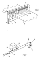
- the machine includes a frame 1 on which a metal cylinder 2 with smooth ground surface is mounted, on which frame the sheet of material to be measured, indicated by 3, is slided.
- the cylinder is preferably driven by an electric motor 4 or the like or it can be dragged by sheet 3 while moving forward.
- connection between motor and cylinder is by means of a ratchet 5 that allows the cylinder to rotate even while the motor is stopped.
- the cylinder angular position is detected, instant after instant, by an encoder 6 connected to electronic machine control devices which are not illustrated since they are of a known type.
- the scanning head 9 includes a pair of magnetic sensors 11 and 12 and a laser sensor 13 placed between the two magnetic ones.
- Sensors 11 and 12 have the capability of measuring the distance of the cylinder surface from the scanning head while the laser sensor senses the distance of sheet 3 surface.
- the cylinder radius in the point where the magnetic sensor is at the time of measurement, owing to a working imperfection, is a few microns lower than the cylinder radius in the zone where the laser sensor performs its reading.
- the method according to the invention provides for the cylinder surface to be sensed by both sensors 11 and 12 and for the calculation, by interpolation, of the cylinder surface distance in correspondence with the zone where the laser performs its reading.
- the film thickness in that point is determined by simply subtracting the two measured values.
- the cylinder surface is not round but it presents more sectors with variable radius, e.g. with the profile illustrated in figure 2.
- a second encoder checks the angular position of this part of the cylinder.
- the scanning head is brought in correspondence with such zone 14 of the cylinder and a first reading is performed, holding the head standstill, by sensing the cylinder surface in correspondence with a plane perpendicular to the axis by means of one of the magnetic sensors.
- the head is then moved, thereby bringing the laser sensor in correspondence with the same point and the reading is performed again, the same reading being thereafter repeated upon bringing to the same point the second sensor.
- Three readings are then available, all relevant to the same surface known a priori , that allow, by comparison, to calibrate the machine by adjusting the response curves of the magnetic sensors as a function of the readings values given by the laser.
- Figure 4 shows a block diagram relative to such calibration function.
- the calibration zone shall be preferably obtained in correspondence with one of the cylinder ends and such cylinder part assigned to calibration may be set to rotate independently from the remaining part. Such an arrangement allows the calibration at an optimum revolving speed, both with the main roller stopped and during the film sliding, to be performed.
- the film thickness in a given point is given by the difference between the distance as measured by the laser and the distance obtained based on the suitably averaged measurements of the two magnetic sensors.
- Th(x, ⁇ ) L(x, ⁇ ) - M(x, ⁇ )
- a matrix constiting of a series of cells each corresponding to a cylinder surface zone defined in any case by abscissa and angular position is formed and, at every passage of the heads, the values read in the zones corresponding to the different cells are stored.
- the reading heads perform a series of scannings by moving in a direction parallel to the cylinder axis and, for each reading, the program checks whether the values corresponding to the zones comprised between the reading points between the two magnetic sensors are stored in the table.
- the magnetic sensor readings are stored and inserted into the matrix where they replace the previous ones, in order to keep the table updated and thereby compensate for possible variations or reading errors due e.g. to temperature variations etc.
- FIG. 3 shows the block diagram of the above method.
Landscapes
- Physics & Mathematics (AREA)
- General Physics & Mathematics (AREA)
- Length Measuring Devices By Optical Means (AREA)
- Measurement Of Length, Angles, Or The Like Using Electric Or Magnetic Means (AREA)
- Length Measuring Devices With Unspecified Measuring Means (AREA)
Claims (8)
- Vorrichtung zum Messen der Dicke eines sich bewegenden Films, welcher aufweist:einen Metallzylinder, über den der Film (3) in gleitendem Kontakt bewegt wird, undeinen Abtastkopf (8), der ausgelegt ist, um sich parallel zu der Metallzylinderachse zu bewegen und einen Lasersensor (13) sowie einen magnetischen Sensor (11, 12) enthält,dadurch gekennzeichnet, daßder Abtastkopf (8) mit einem weiteren gesonderten magnetischen Sensor (12, 11) ausgestattet ist, wobei der Lasersensor (13) in einer Zwischenstellung zwischen den beiden magnetischen Sensoren (11, 12) angeordnet ist, und die beiden magnetischen Sensoren (11, 12) sowie der Lasersensor (13) in der Bewegungsrichtung des Abtastkopfes (8) ausgerichtet sind, und daßMittel bereitgestellt sind, um von den magnetischen Sensoren (11, 12) einen interpolierten Wert zu erhalten, welcher der Entfernung zu der Metalloberfläche entspricht, die sich unterhalb des Zielbereichs auf dem Lasersensor (13) auf dem Film (3) befindet.
- Vorrichtung nach Anspruch 1, dadurch gekennzeichnet, daß der Metallzylinder im Leerlauf ist und mittels des Films (3) durch Zug gedreht wird.
- Vorrichtung nach Anspruch 1 und 2, dadurch gekennzeichnet, daß sie an einem Ende des Zylinders einen Kalibrierungsbereich aufweist, in welchem die Oberfläche des Zylinders ein a priori bekanntes Profil hat, wobei geeignete Mittel vorgesehen sind, um den Abtastkopt (8) zu dem Bereich zu bewegen, um eine Reihe von Messungen durchzuführen, während der Kopf (8) mittels der beiden magnetischen Sensoren (11, 12) bzw. dem optischen Lasersensor (13) in seiner Stellung gehalten wird, sowie Mittel zum Einstellen der Reaktionskurven der magnetischen sensoren in Abhängigkeit von den Messungen von dem optischen Sensor vorgesehen sind.
- Vorrichtung nach Anspruch 3, dadurch gekennzeichnet, daß die Oberfläche des Kalibrierungsbereichs des Zylinders aus einer Reihe von Kreisbögen mit unterschiedlichem Durchmesser besteht.
- Verfahren zum Messen der Dicke eines Films (3), der sich in gleitendem Kontakt über eine metallische Referenzoberfläche bewegt, mittels einer Vorrichtung nach einem der Ansprüche 1 bis 4, wobei das Verfahren die folgenden Schritte aufweist:Messen einer.Entfernung zu der Filmoberfläche mittels eines Lasersensors (13) ;Messen einer Entfernung zu der Metalloberfläche mittels magnetischer Sensoren (11; 12);Abschätzen der Entfernung der Metalloberfläche, die sich unterhalb des Zielbereiches des Lasersensors befindet, durch Interpolation; undBerechnen der Differenz zwischen den beiden Messungen.
- Verfahren nach Anspruch 5, bei welchem bei jedem abgelesenen Meßwert die durch die magnetischen Sensoren (11, 12) erfaßten Entfernungen gespeichert werden, wobei jede solcher Messungen einem Koordinatenpaar zugeordnet wird, das geeignet ist, einen wohldefinierten Bereich der Metalloberfläche zu lokalisieren; eine Karte der Metalloberfläche aufgebaut wird und eine solche Karte verwendet wird, um während den darauffolgenden Durchläufen die Entfernungen zu korrigieren, die man durch Interpolation von den Messungen erhalten hat, die durch magnetischen Sensoren (11, 12) durchgeführt wurden.
- Verfahren nach Anspruch 6, bei welchem bei jedem Abtasten durch die magnetischen Ablesevorrichtungen (11, 12) die Werte bezüglich der Entfernung der Metalloberflache in Übereinstimmung mit den Zwischenpunkten von der Karte abgelesen werden und die Entfernung der Metalloberfläche in Übereinstimmung mit dem Laserablesebereich mittels einer Polynom-Interpolation zwischen dem von der Karte abgelesenen Zwischenwert und den durch die magnetischen Sensoren (11, 12) erfaßten Werten gewonnen wird.
- Verfahren nach einem der Ansprüche 5 bis 7, welches einen Selbstkalibrierungsschritt aufweist, bei welchem man, während man den Kopf (8) im Stillstand hält, Messungen mittels der magnetischen Sensoren (11, 12) und dem Lasersensor (13) der Reihe nach in Übereinstimmung mit ein und demselben Oberlächenbereich durchführt, dessen Profil a priori bekannt ist, und wobei die Reaktionskurven der magnetischen Sensoren (11, 12) gemäß einer Funktion einer durch die Laserablesevorrichtung (13) bereitgestellten Kurve korrigiert werden.
Applications Claiming Priority (2)
| Application Number | Priority Date | Filing Date | Title |
|---|---|---|---|
| ITMI930092A IT1263789B (it) | 1993-01-22 | 1993-01-22 | Metodo e apparecchio comprendente due sensori magnetici ed un misuratore laser per misurare lo spessore di un film |
| ITMI930092 | 1993-01-22 |
Publications (2)
| Publication Number | Publication Date |
|---|---|
| EP0607938A1 EP0607938A1 (de) | 1994-07-27 |
| EP0607938B1 true EP0607938B1 (de) | 1997-09-10 |
Family
ID=11364718
Family Applications (1)
| Application Number | Title | Priority Date | Filing Date |
|---|---|---|---|
| EP94100712A Expired - Lifetime EP0607938B1 (de) | 1993-01-22 | 1994-01-19 | Verfahren und Vorrichtung, zwei magnetische Sensoren und eine Laser-Messeinrichtung enthaltend, für das Messen der Dicke eines Filmes |
Country Status (4)
| Country | Link |
|---|---|
| EP (1) | EP0607938B1 (de) |
| AT (1) | ATE158075T1 (de) |
| DE (1) | DE69405415T2 (de) |
| IT (1) | IT1263789B (de) |
Families Citing this family (7)
| Publication number | Priority date | Publication date | Assignee | Title |
|---|---|---|---|---|
| IT1283347B1 (it) * | 1996-07-29 | 1998-04-17 | Electronic Systems Spa | Metodo ed apperecchiatura per misurare con precisione un film che avanza,su tutta la sua superficie |
| AT408580B (de) * | 1997-11-21 | 2002-01-25 | Bierbaumer Hans Peter Dr | Messvorrichtung zumindest zur ermittlung der dicke einer bahn sowie verfahren hierfür |
| US20020190710A1 (en) * | 2001-02-13 | 2002-12-19 | Asm Automation Sensorik Messtechnik Gmbh | Magnetic length measuring device |
| EP2837484B1 (de) | 2013-08-14 | 2020-10-21 | Electronic Systems S.p.A. | Vorrichtung zur automatischen Analyse von Extrusionsfolien |
| CN115436387A (zh) * | 2022-10-08 | 2022-12-06 | 山东中为电子科技有限公司 | 一种陶瓷膜带外观标记装置 |
| CN118640810B (zh) * | 2024-08-15 | 2024-10-22 | 江苏众盈精特科技有限公司 | 一种精密钢管线激光测厚方法 |
| CN120740461B (zh) * | 2025-08-15 | 2025-12-30 | 连云港市金田高新材料有限公司 | 一种高性能膜材料在线测厚仪 |
Family Cites Families (4)
| Publication number | Priority date | Publication date | Assignee | Title |
|---|---|---|---|---|
| JPS61254812A (ja) * | 1985-05-08 | 1986-11-12 | Meisan Kk | 非磁性体シ−ト厚さ連続測定装置 |
| JPH0648185B2 (ja) * | 1988-10-12 | 1994-06-22 | 明産株式会社 | シート厚さ測定装置 |
| US4977853A (en) * | 1989-06-01 | 1990-12-18 | E. I. Du Pont De Nemours And Company | Non-contact wet or dry film thickness measuring device |
| US5485082A (en) * | 1990-04-11 | 1996-01-16 | Micro-Epsilon Messtechnik Gmbh & Co. Kg | Method of calibrating a thickness measuring device and device for measuring or monitoring the thickness of layers, tapes, foils, and the like |
-
1993
- 1993-01-22 IT ITMI930092A patent/IT1263789B/it active IP Right Grant
-
1994
- 1994-01-19 EP EP94100712A patent/EP0607938B1/de not_active Expired - Lifetime
- 1994-01-19 AT AT94100712T patent/ATE158075T1/de not_active IP Right Cessation
- 1994-01-19 DE DE69405415T patent/DE69405415T2/de not_active Expired - Fee Related
Also Published As
| Publication number | Publication date |
|---|---|
| EP0607938A1 (de) | 1994-07-27 |
| IT1263789B (it) | 1996-08-29 |
| ATE158075T1 (de) | 1997-09-15 |
| ITMI930092A0 (it) | 1993-01-22 |
| DE69405415T2 (de) | 1998-01-22 |
| ITMI930092A1 (it) | 1994-07-22 |
| DE69405415D1 (de) | 1997-10-16 |
Similar Documents
| Publication | Publication Date | Title |
|---|---|---|
| KR920010735B1 (ko) | 롤프로필 계측방법 및 장치 | |
| US4375921A (en) | Dimension measuring apparatus | |
| US6453730B2 (en) | Surface texture measuring instrument, surface texture measuring method and stylus radius measuring instrument | |
| EP0607938B1 (de) | Verfahren und Vorrichtung, zwei magnetische Sensoren und eine Laser-Messeinrichtung enthaltend, für das Messen der Dicke eines Filmes | |
| CA2091727A1 (en) | Method and an apparatus for sensing of wheel parameters in a wheel balancing machine | |
| JPH0441922B2 (de) | ||
| KR960013682B1 (ko) | 스틸영역 사이즈 측정 방법 및 장치 | |
| JP2746511B2 (ja) | 単結晶インゴットのオリエンテーションフラット幅測定方法 | |
| JPS5842904A (ja) | 測長装置 | |
| JP2635913B2 (ja) | 測長あるいは測角装置の方法 | |
| JP2756544B2 (ja) | シート厚み計測方法 | |
| JPH0465610A (ja) | 管体の形状測定装置 | |
| JPH05240609A (ja) | ローラ偏心量測定装置 | |
| JP2675662B2 (ja) | 自動板厚測定装置 | |
| JP2000114327A (ja) | 半導体ウェーハ抵抗率測定器 | |
| JPS6247505A (ja) | 圧延された金属薄板及び金属帯材の厚さを測定するための装置及びこの装置を基準調整するための方法 | |
| JPH05231856A (ja) | 厚み測定装置 | |
| US20240159685A1 (en) | Compact-Cross Direction C-Frame Scanner | |
| JPS6254109A (ja) | 帯状体の巾・蛇行測定装置 | |
| JPH06186028A (ja) | 長尺材真直度測定方法 | |
| JPH07115139B2 (ja) | 連続鋳造用ロール対間隔測定方法・装置 | |
| JPH04364410A (ja) | 非接触式板厚測定方法 | |
| JPH06273103A (ja) | 円筒状物体の外径測定方法 | |
| JPS63277916A (ja) | 帯状物体の反り量計測装置 | |
| JPH08247742A (ja) | 帯状物の2次元形状測定装置 |
Legal Events
| Date | Code | Title | Description |
|---|---|---|---|
| PUAI | Public reference made under article 153(3) epc to a published international application that has entered the european phase |
Free format text: ORIGINAL CODE: 0009012 |
|
| AK | Designated contracting states |
Kind code of ref document: A1 Designated state(s): AT BE CH DE DK ES FR GB GR IE IT LI LU MC NL PT SE |
|
| 17P | Request for examination filed |
Effective date: 19950109 |
|
| 17Q | First examination report despatched |
Effective date: 19961004 |
|
| GRAG | Despatch of communication of intention to grant |
Free format text: ORIGINAL CODE: EPIDOS AGRA |
|
| GRAH | Despatch of communication of intention to grant a patent |
Free format text: ORIGINAL CODE: EPIDOS IGRA |
|
| GRAH | Despatch of communication of intention to grant a patent |
Free format text: ORIGINAL CODE: EPIDOS IGRA |
|
| GRAA | (expected) grant |
Free format text: ORIGINAL CODE: 0009210 |
|
| AK | Designated contracting states |
Kind code of ref document: B1 Designated state(s): AT BE CH DE DK ES FR GB GR IE IT LI LU MC NL PT SE |
|
| PG25 | Lapsed in a contracting state [announced via postgrant information from national office to epo] |
Ref country code: NL Free format text: LAPSE BECAUSE OF FAILURE TO SUBMIT A TRANSLATION OF THE DESCRIPTION OR TO PAY THE FEE WITHIN THE PRESCRIBED TIME-LIMIT Effective date: 19970910 Ref country code: LI Effective date: 19970910 Ref country code: GR Free format text: LAPSE BECAUSE OF FAILURE TO SUBMIT A TRANSLATION OF THE DESCRIPTION OR TO PAY THE FEE WITHIN THE PRESCRIBED TIME-LIMIT Effective date: 19970910 Ref country code: FR Free format text: THE PATENT HAS BEEN ANNULLED BY A DECISION OF A NATIONAL AUTHORITY Effective date: 19970910 Ref country code: ES Free format text: THE PATENT HAS BEEN ANNULLED BY A DECISION OF A NATIONAL AUTHORITY Effective date: 19970910 Ref country code: DK Free format text: LAPSE BECAUSE OF NON-PAYMENT OF DUE FEES Effective date: 19970910 Ref country code: CH Effective date: 19970910 Ref country code: BE Effective date: 19970910 Ref country code: AT Effective date: 19970910 |
|
| REF | Corresponds to: |
Ref document number: 158075 Country of ref document: AT Date of ref document: 19970915 Kind code of ref document: T |
|
| ITF | It: translation for a ep patent filed | ||
| REG | Reference to a national code |
Ref country code: CH Ref legal event code: EP |
|
| REF | Corresponds to: |
Ref document number: 69405415 Country of ref document: DE Date of ref document: 19971016 |
|
| ET | Fr: translation filed | ||
| PG25 | Lapsed in a contracting state [announced via postgrant information from national office to epo] |
Ref country code: SE Effective date: 19971210 Ref country code: PT Effective date: 19971210 |
|
| PG25 | Lapsed in a contracting state [announced via postgrant information from national office to epo] |
Ref country code: LU Free format text: LAPSE BECAUSE OF NON-PAYMENT OF DUE FEES Effective date: 19980119 Ref country code: IE Free format text: LAPSE BECAUSE OF NON-PAYMENT OF DUE FEES Effective date: 19980119 Ref country code: GB Free format text: LAPSE BECAUSE OF NON-PAYMENT OF DUE FEES Effective date: 19980119 |
|
| REG | Reference to a national code |
Ref country code: IE Ref legal event code: FG4D Free format text: 76368 |
|
| NLV1 | Nl: lapsed or annulled due to failure to fulfill the requirements of art. 29p and 29m of the patents act | ||
| REG | Reference to a national code |
Ref country code: CH Ref legal event code: PL |
|
| PLBE | No opposition filed within time limit |
Free format text: ORIGINAL CODE: 0009261 |
|
| STAA | Information on the status of an ep patent application or granted ep patent |
Free format text: STATUS: NO OPPOSITION FILED WITHIN TIME LIMIT |
|
| PG25 | Lapsed in a contracting state [announced via postgrant information from national office to epo] |
Ref country code: MC Free format text: LAPSE BECAUSE OF NON-PAYMENT OF DUE FEES Effective date: 19980731 |
|
| 26N | No opposition filed | ||
| GBPC | Gb: european patent ceased through non-payment of renewal fee |
Effective date: 19980119 |
|
| PG25 | Lapsed in a contracting state [announced via postgrant information from national office to epo] |
Ref country code: DE Free format text: LAPSE BECAUSE OF NON-PAYMENT OF DUE FEES Effective date: 19981001 |
|
| REG | Reference to a national code |
Ref country code: FR Ref legal event code: ST |
|
| REG | Reference to a national code |
Ref country code: IE Ref legal event code: MM4A |
|
| PG25 | Lapsed in a contracting state [announced via postgrant information from national office to epo] |
Ref country code: IT Free format text: LAPSE BECAUSE OF NON-PAYMENT OF DUE FEES Effective date: 20050119 |