EP0608101A2 - Compteur de scintillation - Google Patents
Compteur de scintillation Download PDFInfo
- Publication number
- EP0608101A2 EP0608101A2 EP94300337A EP94300337A EP0608101A2 EP 0608101 A2 EP0608101 A2 EP 0608101A2 EP 94300337 A EP94300337 A EP 94300337A EP 94300337 A EP94300337 A EP 94300337A EP 0608101 A2 EP0608101 A2 EP 0608101A2
- Authority
- EP
- European Patent Office
- Prior art keywords
- scintillation
- fiber
- light
- radiation
- intensity
- Prior art date
- Legal status (The legal status is an assumption and is not a legal conclusion. Google has not performed a legal analysis and makes no representation as to the accuracy of the status listed.)
- Granted
Links
Images




Classifications
-
- G—PHYSICS
- G01—MEASURING; TESTING
- G01T—MEASUREMENT OF NUCLEAR OR X-RADIATION
- G01T1/00—Measuring X-radiation, gamma radiation, corpuscular radiation, or cosmic radiation
- G01T1/16—Measuring radiation intensity
- G01T1/20—Measuring radiation intensity with scintillation detectors
- G01T1/201—Measuring radiation intensity with scintillation detectors using scintillating fibres
-
- G—PHYSICS
- G01—MEASURING; TESTING
- G01T—MEASUREMENT OF NUCLEAR OR X-RADIATION
- G01T1/00—Measuring X-radiation, gamma radiation, corpuscular radiation, or cosmic radiation
- G01T1/16—Measuring radiation intensity
- G01T1/20—Measuring radiation intensity with scintillation detectors
- G01T1/2008—Measuring radiation intensity with scintillation detectors using a combination of different types of scintillation detectors, e.g. phoswich
Definitions
- the present invention relates to a scintillation counter for detecting radiation such a ⁇ srays. More particularly, the present invention relates to the scintillation counter being for in vitro or in vivo detection of ⁇ rays or being for detecting ⁇ rays from radioactive contamination in small diameter pipes at, for example, nuclear power plants.
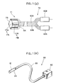
- Japanese Patent Application Publication Kokai No. HE12-206786 describes the scintillation counter 50 shown in Fig. 1 (a) for in vivo detection of ⁇ rays emitted from an organism injected with a radioactive substance.
- ⁇ rays include electrons ( ⁇ - ) and positrons ( ⁇ + ).
- the scintillation counter 50 includes a scintillation fiber 51 and an optical detector 52 joined by an optical fiber 53.
- the scintillation fiber 51 is inserted as a probe into the area.
- the scintillation fiber 51 also picks up y rays from other sources, which are then converted into a signal.
- the signal appears as a background noise which lowers the precision of the ⁇ ray measurement.
- Japanese Patent Application Publication Kokai No. HE14-274792 describes a scintillation counter 60 shown in Fig. 1 (b) for detecting the distribution of radioactive substances in the internal wall of a pipe.
- the scintillation probe 61 of the scintillation counter 60 has a bundle of a plurality of scintillation fibers.
- the bundle consists of two groups of parallel scintillation fibers: a measurement fiber group 61A and a reference fiber group 61 B.
- the measurement fiber group 61A surrounds the reference fiber group 61 B.
- the reference fiber group 61 B consists of a plurality of parallel scintillation fibers 161 Beach of which is covered with a shield material 64 for blocking out ⁇ rays, as shown in Figure 1(c). Therefore, the scintillation fibers 161B of the reference fiber group 61 B are sensitive to only y rays.
- the measurement fiber group 61A consists of a plurality of parallel scintillation fibers 161Aeach of which is not covered with such a shield material 64. Accordingly, the scintillation fibers 161A of the measurement fiber group 61A are sensitive to both ⁇ rays and y rays, similarly as the scintillation fiber 51 of Fig. 1 (a).
- a plurality of optical fibers 63A connect the plural scintillation fibers 161A to an optical detector62A.
- a plurality of optical fibers 63B connect the plural scintillation fibers 161 B to an optical detector 62B.
- the fiber bundle 61 can be inserted as a probe into an object to be measured. The intensity of ⁇ rays only can be measured by subtracting the value detected by the optical detector 62B from the value detected by the optical detector 62A.
- This publication also describes the scintillation counter 70 shown in Fig. 1 (d) wherein a plurality of scintillation fibers 171A of a measurement fiber group 71A are paired with a plurality of scintillation fibers 171B (each covered with a (3-ray shield material 64) of the reference fiber group 71 B.
- a scintillation probe 71 is formed by attaching the pairs of scintillation fibers 171A and 171 B to the outer surface of a cylindrical holder 75 at appropriate intervals in the circumferential direction.
- Each of the probes 61 and 71 of the above- described scintillation counters is thus formed from a bundle of a plurality of parallel scintillation fibers for detecting the distribution of radiation. Accordingly, the probes 61 and 71 become too thick to be inserted into pipes with small diameters or living objects, particularly small animals.
- the scintillation counter 80 has a single scintillation fiber 81, covered with a (3-ray shield material 84, connected to an optical detector 82 by an optical fiber 83.
- a single scintillation fiber 81 covered with a (3-ray shield material 84, connected to an optical detector 82 by an optical fiber 83.
- two fibers i.e., the scintillation fiber 61 and the scintillation fiber 81, must be inserted as two probes into the object to be measured.
- This invention aims to solve the above described problems and provide a scintillation counter for detecting ⁇ rays only with high accuracy.
- a scintillation counter comprises:
- a scintillation counter comprises:
- the scintillation counter two scintillation fibers with different optical wavelengths are connected in series into a probe, one scintillation fiber being covered with a (3-ray shield.
- the optical signal (scintillation light) generated by the scintillation fiber not covered with a (3-ray shield represents the intensity of both ⁇ rays and y rays.
- This optical signal is transmitted through the optical fiber and separated by the light separating means toward the first optical detector means. The separated optical signal is incident upon the first optical detector means where its intensity is detected.
- the scintillation fiber covered with a (3-ray shied has its sensitivity for rays greatly reduced, the optical signal (scintillation light) generated by this scintillation fiber represents almost only the intensity of y rays.
- the optical signal is transmitted through the optical fiber and separated by the light separating means toward the second optical detector means. Then, the separated optical signal is incident on the second optical detector means where its intensity is detected.
- the intensity of only the ⁇ rays can be detected by subtracting the intensity of the optical signal (representing the intensity of only y rays) detected by the second optical detector means from the intensity of the optical signal (representing the intensity of both ⁇ rays and y rays) detected by the first optical detector.
- a scintillation counter according to a first preferred embodiment of the present invention will be described below while referring to Figs. 2 through 8.
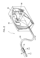
- Fig. 2 is a perspective diagram showing the overall structure of a scintillation counter 1 according to the first preferred embodiment.
- the scintillation counter 1 according to the first preferred embodiment includes: a probe 10 for being inserted into an appropriate position in the object to be measured; an optical fiber20 for transmitting light (i.e., optical signal) emitted from the probe 10; and a detection portion 30 for detecting the intensity of the optical signal transmitted by the optical fiber 20.
- the probe 10 is provided with two scintillation fibers 11 and 12 optically connected in series with a common optical axis.
- the scintillation fiber (reference fiber) 12 is surrounded by a ⁇ -ray shield material film 13 which obstructs passage of ⁇ rays so that only y rays can be incident on the side surface of the scintillation fiber 12.
- a ⁇ -ray shield material film 13 tungsten, iron, lead, or the like can be used. Tungsten is most preferable.
- the scintillation fiber (measurement fiber) 11 is not covered with such a ⁇ -ray shield material 13, both ⁇ rays and y rays can be incident on the scintillation fiber 11.
- the scintillation fiber 11 is formed from such a scintillation fiber as generates scintillation light with wavelength ⁇ 1 upon incidence of radiation such as ⁇ - and y- rays thereto, with the intensity of the scintillation light corresponding to the intensity of the incident radiation.
- the scintillation fiber 12 is formed from such a scintillation fiber as generates scintillation light with another wavelength X 2 upon incidence of radiation such as ⁇ - and y- rays thereto, with the intensity of the scintillation light corresponding to the intensity of the incident radiation.
- the scintillation light generated in each of the scintillation fibers can therefore be considered an optical signal which includes information on the intensity of the corresponding incident radiation.
- the scintillation fiber 11 because the scintillation fiber 11 is not covered with the ⁇ -ray shield material 13, the scintillation fiber 11 generates scintillation light with wavelength ⁇ 1 upon incidence of ⁇ - and y- rays thereto, with the intensity of the scintillation light corresponding to the total intensity of the incident ⁇ - and y- rays.
- the scintillation fiber 12 because the scintillation fiber 12 is covered with the ⁇ -ray shield material 13, the scintillation fiber 12 generates scintillation light with the wavelength X 2 upon incidence of y- rays thereto, with the intensity of the scintillation light corresponding to the intensity of the incident y-rays.
- the cylindrically-shaped scintillation fiber 11 is formed from plastic and includes a polystyrene-based scintillator core Ila and a clad lib with polymethyl methacrylate (PMMA).
- the cylindrically-shaped scintillation fiber 12 is formed from plastic and includes a polystyrene-based scintillator core 12a and a clad 12b with polymethyl methacrylate (PMMA).
- the scintillation fibers 11 and 12 are connected in serial using, for example, adhesive or thermal fusion so that they are optically connected with their optical axes 11X and 12X aligned.
- the scintillation fiber 12 and the optical fiber 20 are connected in serial using, for example, adhesive or thermal fusion so that they are optically connected with their optical axes 12X and 20X aligned. Thus, all the optical axes 11X, 12X and 20X are aligned.
- An appropriately thick ⁇ -ray shield 13 surrounds and covers a peripheral surface 12p (i.e., an external surface of the clad 12b) of the scintillation fiber 12.
- a hollow needle 40 is first inserted into a skin of the living object. Then, the probe 10 is inserted into the hollow needle 40 so as to expose a peripheral surface lip of the scintillation fiber 11 (i.e., an outer surface of the clad lib) and an outer surface of the ⁇ -ray shield 13 in the living object. Accordingly, ⁇ - and y- rays strike both the peripheral surface 11 of the scintillation fiber 11 and the outer surface of the ⁇ -ray shield 13.
- the ⁇ - and y- rays striking the peripheral surface lip enter the core Ila of the fiber 11 through the clad lib, upon which a flash of scintillation light of wavelength ⁇ 1 generates in the core.
- the scintillation light is repeatedly totally internally reflected at the interface between the core and the clad to be propagated toward the core 12a of the scintillation fiber 12.
- the scintillation light is then repeatedly totally internally reflected at the interface between the core 12a and the clad 12b to be propagated in the core 12a toward the optical fiber 20.
- ⁇ - and y- rays also strike the tip end surface lie and enter the fiber 11 to generate the scintillation flash therein.
- an area of the tip end surface lie is very small relative to the area of the peripheral surface 11 p
- the amount of ⁇ - and y- rays entering the fiber 11 through the tip end surface lie is very small relative to that of ⁇ - and y- rays entering the fiber 11 through the peripheral surface 11p. Accordingly, ⁇ - and y- rays enter the fiber 11 mainly through the peripheral surface 11p.
- the ⁇ -ray shield film 13 prevents the ⁇ rays striking the outer surface thereof from being incident on the peripheral surface 12p of the fiber 12. Only the y rays can be incident on the peripheral surface 12p of the fiber 12. The y rays enter the core 12a through the clad 12b, upon which a flash of scintillation light with wavelength X 2 generates in the core. The scintillation light is repeatedly totally internally reflected at the interface between the core and the clad to be propagated toward the optical fiber 20.
- the scintillation light of wavelengths ⁇ 1 and X 2 thus introduced into the optical fiber 20 are then repeatedly totally internally reflected at the interface between a core 20a and a clad 20b of the optical fiber 20 to be propagated in the core 20a toward the detection portion 30.
- Fig. 3(c) shows the case where the probe 10 is inserted into a pipe 41 of a small diameter for detecting ⁇ -rays from radioactive contamination therein. Also in this case, ⁇ - and y- rays enter the scintillation fiber 11 mainly through the peripheral surface 11 p. y- rays only enter the fiber 12 through the ⁇ -ray shield 13 and the peripheral surface 12p.
- Scintillation fibers produced by Bicron Corporation can be used for the scintillation fibers 11 and 12.
- scintillation fibers BCF-20 or BCF-28 both generating scintillation lightwith wavelength of about 480 nm upon incidence of radiation thereto
- scintillation fibers BCF-10 or BCF-12 both generating scintillation light with wavelength of about 430 nm upon incidence of radiation thereto
- the scintillation fibers BCF-20 and BCF-28 should be used as the scintillation fiber 11 positioned at the tip end of the probe 10 opposite the optical fiber20.
- the material of the scintillation fibers BCF-20 and BCF-28 tend to absorb the shorter wavelength light emitted by BCF-10 and BCF-20. If the fibers BCF-20 and BCF-28 are used as the fiber 12, the fiber 12 will greatly absorb the light of wavelength ⁇ 1 generated in the fiber 11 while transmitting the light therethrough. As a general rule, the material of scintillation fiber 12 connected to the optical fiber 20 should have a low absorption coefficient for the wavelength ⁇ 1 generated by the scintillation fiber 11.
- Luminous TC-500-15 produced by Asahi Chemical Industry Co., Ltd, are acceptable for the optical fiber 20.
- the detection portion 30 is provided with: a dichroic mirror 31 for separating the optical signal emitted from the optical fiber 20; optical detectors 32 and 33 for detecting the intensity of the two optical signals after they are separated; and a calculator 34 for subtracting the intensity detected at the optical detectors 32 and 33.
- the scintillation fiber 11 When the scintillation fiber 11 generates wavelength ⁇ 1 and the scintillation fiber 12 generates wavelength ⁇ 2 , two optical signals, i.e., light with wavelength ⁇ 1 (at intensity representing the total intensity of ⁇ rays and y rays) and light with wavelength X 2 (at intensity representing the intensity of only y rays) are both transmitted through the single optical fiber 20.
- the optical fiber 20 propagates or leads the optical signals toward the dichromatic mirror 31. As shown in Fig. 4, the dichromic mirror 31 reflects almost 100% of the optical signal with wavelength ⁇ 1 and transmits almost 100% of the optical signal with wavelength ⁇ 2 .
- the optical detectors 32 and 33 detect the intensity of incident light, i.e., light with wavelengths ⁇ 1 and ⁇ 2 respectively.
- the intensity data detected by the optical detectors 32 and 33 from the optical signals is sent to the calculator 34 which determines the difference between the intensity data from the optical detector 33 and the intensity data from the optical detector 32. In other words, by determining the difference between the intensity data representing intensity of rays only (detected by the optical detector 33) and the intensity data representing intensity of both ⁇ rays and y rays (detected by the optical detector 32), the intensity data of only ⁇ rays can be determined.
- Figs. 5 (a) is a cross-sectional diagram showing one concrete example of the structure around the probe 10.
- the scintillation fibers 11 and 12 are each about 3 mm long and have an external diameter of about 0.5 mm.
- the scintillation fiber 11, the ⁇ -ray shield 13, and the optical fiber 20 are covered with an optical shield pipe 14 made from, for example, aluminum, for blocking out visible light.
- the portion of the optical shield pipe 14 surrounding the optical fiber 20 is covered with a reinforcing pipe 15 made from, for example, 1.0 mm diameter stainless steel.
- a reflective film 16, made of, for example, aluminum, is added to the tip end 11e of the scintillation fiber 11.
- This reflective film 16 receives parts of the optical signals generated in the scintillation fibers 11 and 12, and reflects them back toward the optical fiber 20. This reflective film 16 thus increases a fraction of scintillation light propagating through the optical fiber 20 so they are effectively incident on the optical detectors 32 and 33.
- a modified probe 10' As shown in Fig. 5 (b), sharpening the tip 11e of the scintillation fiber 11 to a point and adding a reflective film 16' thereafter produces a modified probe 10'.
- the angled surfaces produced by this sharpening process can more effectively reflect the scintillation light generated in the scintillation fibers 11 and 12 through the cores ofthe two scintillation fibers 11 and 12 toward the optical fiber 20.
- a portion of the scintillation light travels or propagates towards the optical fiber 20 while another portion passes through the scintillation fiber 11.
- the portion that passes through the scintillation fiber 11 reflects once off both the angled edges of the scintillation fiber 11, thereby reversing direction toward the optical fiber 20.
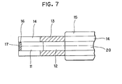
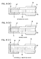
- the ⁇ -ray shield 13 can be formed integrally with the optical shield pipe 14 as shown in Fig. 6 (a), buried in the optical shield pipe 14 as shown in Fig. 6 (b), or mounted externally around the optical shield pipe 14 as shown in Fig. 6 (c). As shown in Fig. 7, the tip end 11e may be further covered with a black pigment film 17 for blocking visible light.
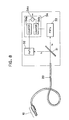
- Fig. 8 is a block diagram showing a concrete example of the detection portion 30.
- the optical signals emitted from the optical fiber 20 are incident on the dichromatic mirror 31.
- the optical signal with wavelength ⁇ 1 reflects off the dichromatic mirror 31 and is incident on the optical detector 32.
- the optical signal with wavelength X 2 is transmitted through the dichromatic mirror 31 and is incident on the optical detector 33.
- the optical detector 32 is provided with a photomultiplier tube (PMT) having a photocathode surface with a high sensitivity for tight with wavelength ⁇ 1 .
- the optical detector 33 is provided with a photomultiplier tube (PMT) having a photocathode surface with a high sensitivity for light with wavelength X2.
- the optical detectors 32 and 33 detect wavelength ⁇ 1 of 480 nm and wavelength X 2 of 430 nm, respectively.
- Each of the detectors 32 and 33 should therefore preferably have a bialkali photocathode surface.
- the optical detector 32 should preferably have a multialkali photocathode surface. This is because multialkali photocathode surfaces generally have a sensitivity peak for longer wavelengths than the bialkali photocathode surfaces. As a general rule, because the optical detector 32 is for detecting a wavelength ( ⁇ 1 ) longer than that (X 2 ) detected by the optical detector 33, the detector 32 should be sensitive for wavelengths longer than those for which the optical detector 33 is sensitive.
- the intensity signal detected by the optical detector 32 is applied to a photon counter 34a in the calculator 34 where an intensity value representing the total intensity of detected y and ⁇ rays is determined.
- the intensity signal detected at the optical detector 33 is applied to the other photon counter 34b of the calculator 34 where an intensity value representing the intensity of detected y rays is determined.
- each of the photon counters 34a and 34b includes such devices as amplifiers, discriminators (single channel analyzers, for example), pulse- shaping circuits, a counter, etc. for performing a well-known photon counting operation.
- the difference between the values calculated at each counter 34a, 34b is taken in a subtraction portion 34c and outputted as intensity data on ⁇ rays only.
- the scintillation fiber 12 is covered with the ⁇ -ray shield material 13.
- the scintillation fiber 11 is covered with a ⁇ -ray shield 13' while the scintillation fiber 12 being not covered with the ⁇ -ray shield material. Accordingly, the scintillation fiber 11 measures y rays only, and the scintillation fiber 12 measures both ⁇ - and y- rays.
- the ⁇ -ray shield 13' is preferably cap shaped so as to cover not only the peripheral surface 11 p but also the tip end surface 11e of the scintillation fiber 11.
- a scintillation fiber for detecting the intensity of only y rays and a scintillation fiber for detecting the total intensity of y rays and ⁇ rays are provided in series to a single probe. By calculating difference between the detected values, the intensity of only ⁇ rays and of only y rays can be determined
- the scintillation counter according to the present invention can therefore detect and provide the intensity of only y rays and of only ⁇ rays using a single probe. Because only one probe is used, there is no second probe to block ⁇ rays, and therefore ⁇ rays have equal access to all sides of the probe. Also, connecting the two scintillation fibers in serial into a single probe sets a single positional relationship between the two scintillation fibers and the object to be measured. Therefore, there is no polarity in regards to the position of the object to be measured, thereby improving the precision of measurements.
- a single probe is thinner than two probes, and can therefore be more easily inserted into a living body which reduces damage to the living body compared to inserting two probes.
- the scintillation counter according to the present invention could be used for measuring intensities of a rays, positrons or other various kinds of radiations. Intensities of various kinds of radiation could be measured byexchang- ing the shield type.
- a dichromatic mirror 31 is used as the light separation means, another wavelength selecting element can be used.
- the scintillation counter of the present invention is widely applicable to various types of in vivo and in vitro detection of ⁇ ray and various types of detection of ⁇ ray from radioactive contamination.
Landscapes
- Physics & Mathematics (AREA)
- Health & Medical Sciences (AREA)
- Life Sciences & Earth Sciences (AREA)
- General Physics & Mathematics (AREA)
- High Energy & Nuclear Physics (AREA)
- Molecular Biology (AREA)
- Spectroscopy & Molecular Physics (AREA)
- Measurement Of Radiation (AREA)
Applications Claiming Priority (2)
| Application Number | Priority Date | Filing Date | Title |
|---|---|---|---|
| JP584493A JPH06214035A (ja) | 1993-01-18 | 1993-01-18 | シンチレーション検出装置 |
| JP5844/93 | 1993-01-18 |
Publications (3)
| Publication Number | Publication Date |
|---|---|
| EP0608101A2 true EP0608101A2 (fr) | 1994-07-27 |
| EP0608101A3 EP0608101A3 (fr) | 1995-07-05 |
| EP0608101B1 EP0608101B1 (fr) | 1998-11-11 |
Family
ID=11622328
Family Applications (1)
| Application Number | Title | Priority Date | Filing Date |
|---|---|---|---|
| EP94300337A Expired - Lifetime EP0608101B1 (fr) | 1993-01-18 | 1994-01-18 | Compteur de scintillation |
Country Status (4)
| Country | Link |
|---|---|
| US (1) | US5424546A (fr) |
| EP (1) | EP0608101B1 (fr) |
| JP (1) | JPH06214035A (fr) |
| DE (1) | DE69414429T2 (fr) |
Cited By (6)
| Publication number | Priority date | Publication date | Assignee | Title |
|---|---|---|---|---|
| WO1996024859A1 (fr) * | 1995-02-06 | 1996-08-15 | Forschungszentrum Jülich GmbH | Procede de mesure et capteur pour la determination in vivo en direct de la dose en equivalent-tissu en radiotherapie |
| FR2735242A1 (fr) * | 1995-06-12 | 1996-12-13 | Commissariat Energie Atomique | Sonde de controle de contamination pour canalisations |
| FR2822239A1 (fr) * | 2001-03-15 | 2002-09-20 | Centre Nat Rech Scient | Procede de mesure de dose d'irradiation |
| WO2006029380A3 (fr) * | 2004-09-09 | 2006-05-26 | Halliburton Energy Serv Inc | Appareil, systemes et procedes de surveillance des rayonnements |
| GB2530785A (en) * | 2014-10-02 | 2016-04-06 | Lightpoint Medical Ltd | Method and apparatus for imaging of radiation sources |
| CN111812700A (zh) * | 2020-07-23 | 2020-10-23 | 中核武汉核电运行技术股份有限公司 | γ-β复合探测装置 |
Families Citing this family (27)
| Publication number | Priority date | Publication date | Assignee | Title |
|---|---|---|---|---|
| US5651047A (en) | 1993-01-25 | 1997-07-22 | Cardiac Mariners, Incorporated | Maneuverable and locateable catheters |
| US5588084A (en) * | 1995-04-28 | 1996-12-24 | Johnson; Kurtis F. | Scintillating optical fibers containing non-uniformly distributed dopants and process for preparing same |
| US5811814A (en) * | 1996-02-12 | 1998-09-22 | Cordis Corporation | Radiation measuring catheter apparatus and method |
| US6076009A (en) * | 1997-05-05 | 2000-06-13 | The University Of Michigan | Solid state beta-sensitive surgical probe |
| JPH10213663A (ja) * | 1997-01-29 | 1998-08-11 | Mitsubishi Electric Corp | 局所線量計 |
| US6782289B1 (en) | 1999-10-08 | 2004-08-24 | The Board Of Trustees Of The Leland Stanford Junior University | Methods and apparatus for characterizing lesions in blood vessels and other body lumens |
| US7328058B2 (en) | 2000-01-04 | 2008-02-05 | Gamma Medica-Ideas, Inc. | Intravascular imaging detector |
| US6602488B1 (en) | 2000-03-03 | 2003-08-05 | Intramedical Imaging, Llc | Use of radiopharmaceuticals and intraoperative radiation probe for delivery of medicinal treatments |
| US6510336B1 (en) | 2000-03-03 | 2003-01-21 | Intra Medical Imaging, Llc | Methods and devices to expand applications of intraoperative radiation probes |
| US7373197B2 (en) * | 2000-03-03 | 2008-05-13 | Intramedical Imaging, Llc | Methods and devices to expand applications of intraoperative radiation probes |
| RU2190240C2 (ru) * | 2000-11-13 | 2002-09-27 | Уральский государственный технический университет (Уральский политехнический институт) | Сцинтилляционный детектор |
| US20020087073A1 (en) * | 2000-12-29 | 2002-07-04 | Hoffman David M. | CT detector reflector useful in detector scintillator array |
| EP1565107A4 (fr) * | 2002-11-14 | 2008-03-05 | Ethicon Endo Surgery Inc | Methodes et dispositifs de detection de cellules tissulaires |
| JP2005024539A (ja) * | 2003-06-10 | 2005-01-27 | Hitachi Ltd | 荷電粒子検出器およびそれを用いた検知装置 |
| WO2005008287A1 (fr) * | 2003-07-18 | 2005-01-27 | Toudai Tlo, Ltd. | Dispositif de surveillance de flux de neutrons thermiques |
| US7651506B2 (en) * | 2003-10-02 | 2010-01-26 | University Of Florida Research Foundation, Inc. | Frameless stereotactic guidance of medical procedures |
| FR2890567B1 (fr) * | 2005-09-13 | 2008-05-30 | Centre Nat Rech Scient | Tete de detection per-operatoire apte a etre couplee a un outil d'exerese |
| US9775573B2 (en) | 2005-09-13 | 2017-10-03 | Centre National De La Recherche Scientifique | Peroperative sensing head adapted to be coupled to an ablation tool |
| JP4675244B2 (ja) * | 2006-01-17 | 2011-04-20 | 三菱電機株式会社 | 放射線測定システム |
| JP2007327967A (ja) * | 2007-07-30 | 2007-12-20 | Toshiba Corp | 放射線弁別測定装置 |
| EP2521157A1 (fr) * | 2011-05-05 | 2012-11-07 | Fei Company | Détecteur segmenté de particules chargées utilisant matériau de scintillation |
| JP6452425B2 (ja) * | 2014-12-11 | 2019-01-16 | 株式会社日立製作所 | 放射線モニタ |
| US10067261B2 (en) | 2015-09-15 | 2018-09-04 | Halliburton Energy Services, Inc. | Downhole photon radiation detection using scintillating fibers |
| JP6932619B2 (ja) * | 2017-11-10 | 2021-09-08 | 株式会社日立製作所 | 放射線モニタ、及び放射線の測定方法 |
| JP6779247B2 (ja) | 2018-03-23 | 2020-11-04 | 株式会社日立製作所 | 超音波診断装置 |
| FR3089306B1 (fr) * | 2018-11-30 | 2021-06-18 | Centre Nat Rech Scient | Détecteur peu-invasif de rayonnements ionisants |
| CN119395740B (zh) * | 2024-10-28 | 2025-09-02 | 深圳大学 | 一种探针型海产品辐射测量仪 |
Family Cites Families (9)
| Publication number | Priority date | Publication date | Assignee | Title |
|---|---|---|---|---|
| JPS58158848A (ja) * | 1982-03-15 | 1983-09-21 | Jeol Ltd | 電子検出器 |
| US4788436A (en) * | 1986-12-24 | 1988-11-29 | Walter Koechner | Radiation sensitive optical fiber and detector |
| JPH067163B2 (ja) * | 1989-02-07 | 1994-01-26 | 浜松ホトニクス株式会社 | 計測用プローブおよびシンチレーション検出器 |
| US4931646A (en) * | 1989-03-17 | 1990-06-05 | The United States Of America As Represented By The Secretary Of The Army | Remote multichannel coincident nuclear detector and characterization system |
| JPH068858B2 (ja) * | 1989-04-06 | 1994-02-02 | 浜松ホトニクス株式会社 | 計測用プローブ |
| US5008546A (en) * | 1990-06-18 | 1991-04-16 | The Regents Of The University Of California | Intraoperative beta probe and method of using the same |
| JP3124306B2 (ja) * | 1991-03-01 | 2001-01-15 | 浜松ホトニクス株式会社 | 管内壁放射物質の分布検出器 |
| US5087818A (en) * | 1991-05-06 | 1992-02-11 | Bicron Corporation | Beta scintillation probe |
| US5313065A (en) * | 1992-09-01 | 1994-05-17 | The Babcock & Wilcox Company | Fiber optic radiation monitor |
-
1993
- 1993-01-18 JP JP584493A patent/JPH06214035A/ja active Pending
-
1994
- 1994-01-18 EP EP94300337A patent/EP0608101B1/fr not_active Expired - Lifetime
- 1994-01-18 DE DE69414429T patent/DE69414429T2/de not_active Expired - Fee Related
- 1994-01-18 US US08/184,198 patent/US5424546A/en not_active Expired - Lifetime
Cited By (11)
| Publication number | Priority date | Publication date | Assignee | Title |
|---|---|---|---|---|
| WO1996024859A1 (fr) * | 1995-02-06 | 1996-08-15 | Forschungszentrum Jülich GmbH | Procede de mesure et capteur pour la determination in vivo en direct de la dose en equivalent-tissu en radiotherapie |
| US5938605A (en) * | 1995-02-06 | 1999-08-17 | Forschungszentrum Julich Gmbh | Measuring process and sensor for on-line in-vivo determination of the tissue-equivalent dose in radiotherapy |
| FR2735242A1 (fr) * | 1995-06-12 | 1996-12-13 | Commissariat Energie Atomique | Sonde de controle de contamination pour canalisations |
| FR2822239A1 (fr) * | 2001-03-15 | 2002-09-20 | Centre Nat Rech Scient | Procede de mesure de dose d'irradiation |
| WO2002075359A1 (fr) * | 2001-03-15 | 2002-09-26 | Centre National De La Recherche Scientifique (Cnrs) | Procede de mesure de dose d'irradiation par un faisceau d'un rayonnement ionisant susceptible de creer du rayonnement cerenkov |
| US7154097B2 (en) | 2001-03-15 | 2006-12-26 | Centre National De La Recherche Scientifique (Cnrs) | Method for measuring a dose of irradiation with a beam of ionizing radiation capable of creating Cherenkov radiation |
| WO2006029380A3 (fr) * | 2004-09-09 | 2006-05-26 | Halliburton Energy Serv Inc | Appareil, systemes et procedes de surveillance des rayonnements |
| GB2530785A (en) * | 2014-10-02 | 2016-04-06 | Lightpoint Medical Ltd | Method and apparatus for imaging of radiation sources |
| EP3012668A3 (fr) * | 2014-10-02 | 2016-07-27 | Lightpoint Medical Ltd | Procédé et appareil pour l'imagerie de sources de rayonnement |
| US9588232B2 (en) | 2014-10-02 | 2017-03-07 | Lightpoint Medical Ltd. | Method and apparatus for imaging of radiation sources |
| CN111812700A (zh) * | 2020-07-23 | 2020-10-23 | 中核武汉核电运行技术股份有限公司 | γ-β复合探测装置 |
Also Published As
| Publication number | Publication date |
|---|---|
| JPH06214035A (ja) | 1994-08-05 |
| EP0608101B1 (fr) | 1998-11-11 |
| EP0608101A3 (fr) | 1995-07-05 |
| US5424546A (en) | 1995-06-13 |
| DE69414429T2 (de) | 1999-04-08 |
| DE69414429D1 (de) | 1998-12-17 |
Similar Documents
| Publication | Publication Date | Title |
|---|---|---|
| US5424546A (en) | Scintillation counter having two scintillation fibers provided in series and which emit at different wavelengths | |
| US5391878A (en) | Multiplexed fiber readout of scintillator arrays | |
| EP0604947B1 (fr) | Dispositif pour la transmission de lumière produit par un détecteur de rayonnement | |
| US5811814A (en) | Radiation measuring catheter apparatus and method | |
| US6333502B1 (en) | Radiation detector, radiation measurement system and radiation measurement method | |
| RU2182715C2 (ru) | Сцинтилляционное оптическое волокно, чувствительное к излучению с низкой энергией, детектор излучения для регистрации частиц излучения с низкой энергией и устройство для контроля источника воды | |
| KR20040022437A (ko) | Pet 스캐너 | |
| JP2000346947A (ja) | 放射線検出装置 | |
| JPH07306270A (ja) | 放射線検出器および放射線検出方法 | |
| CN106291657A (zh) | 一种基于合束闪烁光纤的放射能谱分析系统 | |
| Rushbrooke et al. | Optical fibre readout and performance of small scintillating crystals for a fine-grained gamma detector | |
| KR101320891B1 (ko) | 산란 제거 및 선량 측정이 가능한 그리드 일체형 x선 검출기 | |
| CN111221021A (zh) | 一种辐射剂量测量方法与装置 | |
| CN108489948B (zh) | 一种u型双向光纤荧光辐射传感探头 | |
| JPH09243752A (ja) | 光ファイバ型大面積放射線モニタ | |
| JPH04204079A (ja) | シンチレーション式β線検出器 | |
| Yasuda et al. | Development of scintillation-light-transmission type phoswich detector for simultaneous alpha-and beta (gamma)-ray counting | |
| CN108646282A (zh) | 基于塑料闪烁体的气态氚化水在线探测系统 | |
| CN102451017A (zh) | Pet检测器模块、pet扫描仪系统、核医学图像摄影检测器模块 | |
| JP4621821B2 (ja) | 集光ファイバ、光検出システム、光結合構造、及び放射線検出ユニット | |
| JP3462871B2 (ja) | 放射線検出光伝送装置 | |
| JPS6347686A (ja) | 放射線3次元位置検出装置 | |
| JP2882964B2 (ja) | 放射性液体モニタ | |
| JPH07231884A (ja) | 血中放射能検出装置 | |
| RU2079172C1 (ru) | Устройство контроля толщины внутренней оболочки твэла |
Legal Events
| Date | Code | Title | Description |
|---|---|---|---|
| PUAI | Public reference made under article 153(3) epc to a published international application that has entered the european phase |
Free format text: ORIGINAL CODE: 0009012 |
|
| AK | Designated contracting states |
Kind code of ref document: A2 Designated state(s): CH DE FR GB LI SE |
|
| PUAL | Search report despatched |
Free format text: ORIGINAL CODE: 0009013 |
|
| AK | Designated contracting states |
Kind code of ref document: A3 Designated state(s): CH DE FR GB LI SE |
|
| 17P | Request for examination filed |
Effective date: 19951221 |
|
| 17Q | First examination report despatched |
Effective date: 19970425 |
|
| GRAG | Despatch of communication of intention to grant |
Free format text: ORIGINAL CODE: EPIDOS AGRA |
|
| GRAG | Despatch of communication of intention to grant |
Free format text: ORIGINAL CODE: EPIDOS AGRA |
|
| GRAH | Despatch of communication of intention to grant a patent |
Free format text: ORIGINAL CODE: EPIDOS IGRA |
|
| GRAH | Despatch of communication of intention to grant a patent |
Free format text: ORIGINAL CODE: EPIDOS IGRA |
|
| GRAA | (expected) grant |
Free format text: ORIGINAL CODE: 0009210 |
|
| AK | Designated contracting states |
Kind code of ref document: B1 Designated state(s): CH DE FR GB LI SE |
|
| REG | Reference to a national code |
Ref country code: CH Ref legal event code: NV Representative=s name: ISLER & PEDRAZZINI AG Ref country code: CH Ref legal event code: EP |
|
| REF | Corresponds to: |
Ref document number: 69414429 Country of ref document: DE Date of ref document: 19981217 |
|
| ET | Fr: translation filed | ||
| PLBE | No opposition filed within time limit |
Free format text: ORIGINAL CODE: 0009261 |
|
| STAA | Information on the status of an ep patent application or granted ep patent |
Free format text: STATUS: NO OPPOSITION FILED WITHIN TIME LIMIT |
|
| 26N | No opposition filed | ||
| REG | Reference to a national code |
Ref country code: GB Ref legal event code: IF02 |
|
| PGFP | Annual fee paid to national office [announced via postgrant information from national office to epo] |
Ref country code: DE Payment date: 20030130 Year of fee payment: 10 |
|
| PG25 | Lapsed in a contracting state [announced via postgrant information from national office to epo] |
Ref country code: DE Free format text: LAPSE BECAUSE OF NON-PAYMENT OF DUE FEES Effective date: 20040803 |
|
| PGFP | Annual fee paid to national office [announced via postgrant information from national office to epo] |
Ref country code: SE Payment date: 20060105 Year of fee payment: 13 |
|
| PGFP | Annual fee paid to national office [announced via postgrant information from national office to epo] |
Ref country code: FR Payment date: 20060110 Year of fee payment: 13 |
|
| PGFP | Annual fee paid to national office [announced via postgrant information from national office to epo] |
Ref country code: CH Payment date: 20060113 Year of fee payment: 13 |
|
| PGFP | Annual fee paid to national office [announced via postgrant information from national office to epo] |
Ref country code: GB Payment date: 20060118 Year of fee payment: 13 |
|
| PG25 | Lapsed in a contracting state [announced via postgrant information from national office to epo] |
Ref country code: SE Free format text: LAPSE BECAUSE OF NON-PAYMENT OF DUE FEES Effective date: 20070119 |
|
| PG25 | Lapsed in a contracting state [announced via postgrant information from national office to epo] |
Ref country code: LI Free format text: LAPSE BECAUSE OF NON-PAYMENT OF DUE FEES Effective date: 20070131 Ref country code: CH Free format text: LAPSE BECAUSE OF NON-PAYMENT OF DUE FEES Effective date: 20070131 |
|
| REG | Reference to a national code |
Ref country code: CH Ref legal event code: PL |
|
| EUG | Se: european patent has lapsed | ||
| GBPC | Gb: european patent ceased through non-payment of renewal fee |
Effective date: 20070118 |
|
| REG | Reference to a national code |
Ref country code: FR Ref legal event code: ST Effective date: 20070930 |
|
| PG25 | Lapsed in a contracting state [announced via postgrant information from national office to epo] |
Ref country code: GB Free format text: LAPSE BECAUSE OF NON-PAYMENT OF DUE FEES Effective date: 20070118 |
|
| PG25 | Lapsed in a contracting state [announced via postgrant information from national office to epo] |
Ref country code: FR Free format text: LAPSE BECAUSE OF NON-PAYMENT OF DUE FEES Effective date: 20070131 |