EP0608475A2 - Kapazitiver elektromagnetischer Durchflussmesser - Google Patents
Kapazitiver elektromagnetischer Durchflussmesser Download PDFInfo
- Publication number
- EP0608475A2 EP0608475A2 EP93113216A EP93113216A EP0608475A2 EP 0608475 A2 EP0608475 A2 EP 0608475A2 EP 93113216 A EP93113216 A EP 93113216A EP 93113216 A EP93113216 A EP 93113216A EP 0608475 A2 EP0608475 A2 EP 0608475A2
- Authority
- EP
- European Patent Office
- Prior art keywords
- flowtube
- fluid
- conduit
- electromagnetic flowmeter
- capacitance
- Prior art date
- Legal status (The legal status is an assumption and is not a legal conclusion. Google has not performed a legal analysis and makes no representation as to the accuracy of the status listed.)
- Ceased
Links
Images


Classifications
-
- G—PHYSICS
- G01—MEASURING; TESTING
- G01F—MEASURING VOLUME, VOLUME FLOW, MASS FLOW OR LIQUID LEVEL; METERING BY VOLUME
- G01F1/00—Measuring the volume flow or mass flow of fluid or fluent solid material wherein the fluid passes through a meter in a continuous flow
- G01F1/002—Measuring the volume flow or mass flow of fluid or fluent solid material wherein the fluid passes through a meter in a continuous flow wherein the flow is in an open channel
-
- G—PHYSICS
- G01—MEASURING; TESTING
- G01F—MEASURING VOLUME, VOLUME FLOW, MASS FLOW OR LIQUID LEVEL; METERING BY VOLUME
- G01F1/00—Measuring the volume flow or mass flow of fluid or fluent solid material wherein the fluid passes through a meter in a continuous flow
- G01F1/56—Measuring the volume flow or mass flow of fluid or fluent solid material wherein the fluid passes through a meter in a continuous flow by using electric or magnetic effects
- G01F1/58—Measuring the volume flow or mass flow of fluid or fluent solid material wherein the fluid passes through a meter in a continuous flow by using electric or magnetic effects by electromagnetic flowmeters
- G01F1/584—Measuring the volume flow or mass flow of fluid or fluent solid material wherein the fluid passes through a meter in a continuous flow by using electric or magnetic effects by electromagnetic flowmeters constructions of electrodes, accessories therefor
-
- G—PHYSICS
- G01—MEASURING; TESTING
- G01F—MEASURING VOLUME, VOLUME FLOW, MASS FLOW OR LIQUID LEVEL; METERING BY VOLUME
- G01F1/00—Measuring the volume flow or mass flow of fluid or fluent solid material wherein the fluid passes through a meter in a continuous flow
- G01F1/56—Measuring the volume flow or mass flow of fluid or fluent solid material wherein the fluid passes through a meter in a continuous flow by using electric or magnetic effects
- G01F1/58—Measuring the volume flow or mass flow of fluid or fluent solid material wherein the fluid passes through a meter in a continuous flow by using electric or magnetic effects by electromagnetic flowmeters
- G01F1/60—Circuits therefor
Definitions
- the present invention relates to a capacitance-type electromagnetic flowmeter for detecting, via electrostatic capacitances, signal voltages corresponding to flow rates produced in a fluid undergoing measurement and, more particularly, to an improved capacitance-type electromagnetic flowmeter which does not only detect signals from a closed flowtube without being affected by the flow velocity distribution in a fluid when the flowtube is fully filled with the fluid, but which can also detect such signals without being affected either by changes in the level of the fluid or by the flow velocity distribution even if the closed flowtube is not fully filled with the liquid. Furthermore, the invention relates to an improved capacitance-type electromagnetic flowmeter capable of detecting the aforementioned signal voltages without being affected either by changes in the level of the fluid under measurement or by flow velocity distribution even in an open conduit having a free liquid surface.
- Fig. 1 shows the structure of a conventional electromagnetic flowmeter designed to reduce the effect of flow velocity distribution. This structure is disclosed in Japanese Patent Publication No. 28325/1980 entitled “Electromagnetic Flowmeter”. This is described briefly below.
- a tube 10 has an electrically insulated inner surface. Magnets 11 and 12 are disposed on opposite sides of the tube 10 to apply magnetic flux & to the tube 10.
- Plural pairs of electrodes 13a, 13b, 14a, 14b, 15a, 15b, 16a, 16b, and 17a, 17b are mounted on the insulated inner surface of the tube 10.
- the electrodes 13a and 13b are arranged in diametrically opposite relation to each other in the center of the tube 10.
- the electrodes 14a and 14b are respectively located a given distance above the electrodes 13a and 13b, and the electrodes 15a and 15b are respectively located above the electrodes 14a and 14b and spaced a given distance from the electrodes 14a and 14b.
- the electrodes 16a, 17a, 16b, and 17b are successively regularly located downward from the electrodes 13a and 13b, respectively.
- the electrodes 13a and 13b are connected with a first amplifier 18, the electrodes 14a and 14b are connected with a second amplifier 19, the electrodes 15a and 15b are connected with a third amplifier 20, the electrodes 16a and 16b are connected with a fourth amplifier 21, and the electrodes 17a and 17b are connected with a fifth amplifier 22.
- the outputs from these amplifiers 18-22 are applied to a converter 23, which applies the average of these outputs across output terminals 24a and 24b.
- These amplifiers 18-22, the converter 23, and other components together form a signal processor 25.
- the output voltage developed across the output terminals 24a and 24b is in proportion to the flow rate of the fluid flowing through the tube 10.
- the prior art electromagnetic flowmeter constructed as described above cannot sufficiently suppress the effect of the flow velocity distribution unless numerous electrodes in contact with the liquid are provided. This makes the structure and arrangement of the electrodes complex. In addition, liquid might leak from these electrodes.
- the signal processor must incorporate numerous amplifiers for averaging out the signal voltages. This increases cost.
- the mutually spaced electrodes When the tube is not fully filled, the mutually spaced electrodes may be brought into and out of contact with the fluid under measurement by variations in the free liquid surface. Thus, electrochemical potentials on the surfaces of the electrodes vary greatly, resulting in great variations in indicated value.
- an object of the present invention to provide an electromagnetic flowmeter having a simple electrode structure which is unaffected by the flow velocity distribution in liquid and which does not permit leakage of liquid.
- An electromagnetic flowmeter satisfying these objects consists principally of: a flowtube electrically insulated at least on its inner surface; an exciting means for applying a magnetic field to a fluid to be measured in a vertical relation to the axis of said flowtube; and a pair of detecting electrodes mounted in said flowtube and electrically insulated from said fluid.
- the electrodes extend perpendicular to both said axis of the flowtube and said magnetic field.
- This flowmeter is characterized in that the length of each of said electrodes taken axially of said flowtube is so set as to be in proportion to the cosine of an angle made between a line normal to the wall of said flowtube and an axis which is perpendicular to both said axis of the flowtube and to said magnetic field.
- each of said electrodes taken axially of said flowtube is so set as to be in proportion to the cosine of an angle made between a line normal to the wall of said flowtube and an axis which is perpendicular to both said axis of the flowtube and to said magnetic field. Therefore, flow signals originating from various points on the detecting electrodes are produced while weighted with the cosine of the angle described above. As a result, an output can be obtained without being affected by the flow velocity distribution.
- Another electromagnetic flowmeter satisfying the above objects comprises: a conduit which is electrically insulated at least on its inner surface and through which a fluid to be measured flows, the conduit having a free liquid surface therein; an exciting means for applying a magnetic field perpendicular to said free liquid surface; a pair of detecting electrodes mounted in said conduit and electrically insulated from said fluid; and a current-to-voltage converter means for converting electrical current signals produced from said detecting electrodes according to flow rate of said fluid into voltage signals.
- a signal accurately indicating a flow rate can be derived by passing the current signals through current-to-voltage converter means if the inside of the conduit is not fully filled with the fluid, the current signal originating from the detecting electrodes insulated from the fluid.
- FIG. 2 there is shown an electromagnetic flowmeter embodying the concept of the present invention.
- This flowmeter comprises an insulated cylindrical flowtube 30 through which fluid Q to be measured flows.
- a uniform magnetic field B is applied parallel to the axis of the flowtube 30.
- a pair of conductive electrodes 31 and 32 are mounted in the center of the flowtube 30 along the outer wall of the flowtube 30 in opposite relation to each other.
- the electrodes 31 and 32 are electrically insulated from the liquid Q.
- the length of the electrodes 31 and 32 taken along the axis of the flowtube is in proportion to the cosine of an angle 0 made between the curved surface of the flowtube 30 and a line X-X' connecting the centers of the detecting electrodes 31 and 32 at a point at which a line Y-Y' crossing the central cross section of the flowtube 30 intersects the axis Z-Z' of the flowtube.
- the detecting electrode 31 is connected with the inverting input terminal (-) of an operational amplifier 33 whose non-inverting input terminal (+) is connected with a common potential point COM.
- the output terminal of the amplifier 33 is connected with the inverting input terminal (-) via a capacitor C I1 .
- the detecting electrode 32 is connected with the inverting input terminal (-) of an operational amplifier 34 whose non-inverting input terminal (+) is connected with a common potential point COM.
- the output terminal of the amplifier 34 is connected with the inverting input terminal (-) of the amplifier 34 via a capacitor C fz .
- These operational amplifiers 33 and 34 are connected with the non-inverting input terminal (+) and the inverting input terminal (-), respectively, of a third operational amplifier 35.
- This amplifier 35 outputs the difference between the voltage signals from the operational amplifiers 33 and 34 to an output terminal 36.
- the fluid Q undergoing measurement flows through the flowtube 30, producing an electromotive force inside the fluid.
- This force creates a given potential distribution in the fluid along the inner wall of the insulated flowtube 30.
- Composite signal voltages produced by this potential distribution are detected by the electrodes 31 and 32, via electrostatic capacitances C w1 and C w2 , respectively, formed by the flowtube 30.
- the current signals detected by the electrodes 31 and 32 are supplied to the operational amplifiers 33 and 34, respectively, which convert their respective input current signals into voltage signals. The difference between these two voltage signals is output to the output terminal 36 by the operational amplifier 35.
- the flowmeter is able to accurately measure flow rates without being affected by the flow velocity distribution even if the inside of the flowtube 30 is not fully filled or if the flowtube 30 is a partially open conduit. This is described in further detail below.
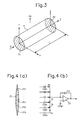
- FIG. 3 the cross section of the flowtube of an electromagnetic flowmeter of interest is uniform along the axis of the flowtube, or z-axis direction, irrespective of the shape of the cross section. It is assumed that the wall of the flowtube is insulated.
- a uniform magnetic field having a strength of Ho is applied in the y-axis direction, perpendicular to the axis of the flowtube.
- the magnetic field covers a length of L in the z-axis direction.
- X-axis is taken at right angles to y- and z-axes.
- a cylindrical region having the length L and surrounded by the inner wall of the flowtube is the subject of analysis.
- S be the area of the curved surface of the cylindrical region.
- a 1 and A 2 be the two cross sections, respectively, which have an area of A.
- a fluid flows in the z-axis direction at a flow rate of Q.
- Maxwell field equations hold at any arbitrary point within the region. If the magnetic field varies slowly, displacement current can be neglected compared with conduction current. Where none of polarization of the fluid, transportation of electric charge by the fluid, generation of electric charge, and annihilation of electric charge take place, the following equations hold: where H is a vector indicating a magnetic field strength, J is a vector indicating a current density, and E is a vector indicating an electric field strength. Let 6 , ⁇ , and v be a specific conductance, permeability, and a vector indicating a flow velocity, respectively.
- Equation (9) is a fundamental equation for a three-dimensional model of an electromagnetic flowmeter.
- equation (10) can take the form where r is the diameter of the cross section of the flowtube, and Bo is ⁇ H 0 .
- the magnetic field strength Ho has an x-axis component and can be given by where H x and Hy are functions of a location.
- equations (4)-(6) do not depend on the magnetic field.
- the vector ( ⁇ v x Ho) included in the right side of equation (7) is given by
- terms containing H x appear.
- Equation (7) is given by By substituting equations (6) and (7)' into equation (5), we have By making L short, the following equation is derived as a formula representing a two-dimensional model:
- H x disappears from the equation.
- Fig. 4(a) is a pictorial representation of the detecting electrode 31 which is divided into n for ease of illustration.
- Fig. 4(b) illustrates the relation with the operational amplifier 33 connected with the electrode 31.
- the electrode 31 is entirely made of one conductive substance.
- the n portions 31 a, 31 b, 31 c, ... , 31 n of the electrode 31 are electrically insulated from each other and mounted on the surface of the insulated flowtube 30 or on the inner wall of the flowtube so as to come into close contact with the surface or wall.
- Electrostatic capacitances C wa , C Wb , C wc , ...., C wn are formed respectively between the detecting electrodes 31 a-31 n and the fluid Q via the insulated flowtube 30.
- Voltages v a , v b , v c , ..., v n are induced on the electrodes 31a-31n, respectively, by the fluid Q. These induced voltages V a- V n are converted into current signals i a , i b , i c , ..., in, respectively, with respective small electrostatic capacitances C wa , C wb , C wc , ..., C wn , and added at the inverting input terminal (-) of the operational amplifier 33. The resulting current is converted back to a voltage by the feedback capacitor C f1 and appears at the output terminal.
- the electrostatic capacitance C wi is so selected that the length of the detecting electrode 31 taken in the z-axis direction of the flowtube 30 is proportional to cos ⁇ i .
- an electromagnetic flowmeter whose output is proportional to the flow rate Q but not affected by the flow velocity distribution is obtained by weighting the electromotive force produced on the inner surface of the flowtube 30 with cos 0, summing up the current signals derived from the whole detecting electrode 31, and delivering the sum current.
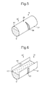
- Fig. 5 is a perspective view showing the structure of such an electromagnetic flowmeter.
- Electrodes 38 and 39 are formed on the outer surface of an insulated circular flowtube 37 such that their length taken in the axis of the flowtube is in proportion to cos 0.
- the fluid Q under measurement fills only a part of the inside of the flowtube.
- a space 40 is left in an upper portion.
- a current signal representing a flow rate is obtained as shown in Fig. 4 by detecting the sum of current signals as a signal indicating the flow rate, in the same way as in Fig. 2.
- the electrode 31 n is not in contact with the fluid Q, the voltage v n is zero. Also, the electrostatic capacitance C wn is zero. Therefore, the impedance at this portion is infinitely large. Hence, this is not added to other currents. That is, only currents converted from electromotive forces produced at the portions where the fluid Q exists are added together. In consequence, the flow rate can be measured correctly, whether the flowtube is filled with liquid or not.
- Fig. 6 is a perspective view of an electromagnetic flowmeter comprising a flowtube having an open conduit 41, which is insulated and takes a U-shaped form.
- the inside of the conduit 41 is filled with a fluid Q under measurement.
- a magnetic field B is applied perpendicularly to a free liquid surface 42.
- Detecting electrodes 43 and 44 having a given length along the axis of the conduit are mounted on the curved surface of the conduit 41.
- the length of the electrodes 43 and 44 taken longitudinally of the conduit is so selected as to be proportional to the cosine of an angle 0 made between a normal to the wall of the conduit and an axis vertical to both the longitudinal direction of the conduit and the magnetic field, while making reference to equation (10).
- Figs. 7(a) and 7(b) are cross-sectional views of electromagnetic flowmeters having open conduits of trapezoidal and triangular cross sections, respectively.
- an insulated conduit 45 has a trapezoidal cross section.
- Detecting electrodes 46 and 47 are mounted on the side wall of this conduit 45. Also in this case, the length of the electrodes 46 and 47 taken longitudinally of the conduit is selected so as to be proportional to cos 0, in the same way as in the case of Fig. 6.
- an insulated conduit 48 assumes a triangular cross section.
- Detecting electrodes 49 and 50 are mounted on the side wall of the conduit.
- the length of the electrodes 46 and 47 taken longitudinally of the conduit is so selected as to be in proportion to cos 0, in the same way as in the structure shown in Fig. 6.
- Fig. 8 is a circuit diagram of a first modification of the aforementioned operational amplifier 33 (Fig. 2) to which an electrical current is supplied.
- This amplifier, indicated by 51 is similar to the amplifier 33 shown in Fig. 2 except that the capacitor C f1 has been replaced by a resistor R 1 .
- An electrostatic capacitance C 1 is formed between the electrode and the fluid Q under measurement. A signal voltage produced in the fluid Q is converted into an electrical current signal by the electrostatic capacitance C 1 , converted into a voltage signal via the resistor Ri, and appears at the output terminal of the operational amplifier 51 as a voltage signal.
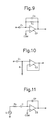
- Fig. 9 is a circuit diagram of a second modification of the aforementioned operational amplifier 33 (Fig. 2) to which an electrical current is supplied.
- a parallel combination of a resistor R 2 and a capacitor C 2 forms a feedback circuit for an operational amplifier 52.
- phase varies between the input and the output. Therefore, it is necessary to take account of phase when signals are treated in succeeding stages.
- Fig. 10 is a circuit diagram of a modification of an operational amplifier to which a voltage is applied.
- a signal voltage is developed in the fluid Q under measurement.
- This signal voltage is converted into a current signal by an electrostatic capacitance C 1 at the input side of an operational amplifier 53, because I » R ; .
- the converted current signal is converted into a voltage signal by a resistor R i .
- This voltage signal is amplified by the amplifier 53.
- This voltage input-type operational amplifier can be applied to an electromagnetic flowmeter comprising an open conduit not fully filled with liquid.
- this amplifier is used with an electromagnetic flowmeter having a flowtube consisting of an open conduit, i.e., the inside of the flowtube is not fully filled with liquid, flow rates cannot be measured accurately.
- the resistor Ro in contact with liquid is inserted in series with the electrostatic capacitor Ci, as shown in Fig. 11.
- the impedance of the capacitor C 1 is much larger than the resistance of the resistor Ro in contact with liquid. Consequently, the measured flow rate is not readily affected by variations in the resistor R o , e.g., the electrical conductivity.
- an exciting means having various waveforms such as rectangular wave and sinusoidal wave can be used.
- the length of detecting electrodes taken axially of a flowtube is varied while maintaining a certain relation given by a function cos 0.
- the effect of the flow velocity distribution can be eliminated by changing the distance between each detecting electrode and a fluid under measurement while maintaining the same relationship given by the function.
- each detecting electrode is provided in the outer surface of the flowtube.
- each detecting electronode can be built in the flowtube.
- capacitance-detection type detecting electrodes are so shaped that errors caused by flow velocity distribution are reduced. Potentials on the inner wall of the flowtube are detected by the detecting electrodes. The weighted mean value of these potentials is extracted. Hence, an electromagnetic flowmeter which is less affected by the flow velocity distribution can be realized.
- the flat shape of the electrodes provides a means for producing the weighted mean value. Consequently, the flowmeter can be fabricated at low cost.
- a receiver circuit is built so as to detect electrical currents. Hence, flow rates can be measured correctly, irrespective of whether the inside of the flowtube is fully filled with liquid or not, and irrespective of the distribution of flow velocities.
- each detecting electrode taken axially of the flowtube is in proportion to the cosine of the angle made between a normal to the wall of the conduit and an axis vertical to both the axis of the flowtube and the magnetic field. Therefore, flow rates in the open conduit can be made independent of variations of the liquid level and are not affected by flow velocity distribution.
- a receiver circuit is built so as to detect voltage signals. Therefore, if the flowtube is filled with liquid, flow rates can be measured correctly.
- the flowtube and the conduit can take various forms, although the same measuring principle is utilized. Consequently, the shape can be adjusted according to the subject of measurement. This can extend the range of applications.
Landscapes
- Physics & Mathematics (AREA)
- Fluid Mechanics (AREA)
- General Physics & Mathematics (AREA)
- Electromagnetism (AREA)
- Measuring Volume Flow (AREA)
Applications Claiming Priority (2)
| Application Number | Priority Date | Filing Date | Title |
|---|---|---|---|
| JP5013211A JP3031096B2 (ja) | 1993-01-29 | 1993-01-29 | 容量式電磁流量計 |
| JP13211/93 | 1993-01-29 |
Publications (2)
| Publication Number | Publication Date |
|---|---|
| EP0608475A2 true EP0608475A2 (de) | 1994-08-03 |
| EP0608475A3 EP0608475A3 (de) | 1995-07-19 |
Family
ID=11826826
Family Applications (1)
| Application Number | Title | Priority Date | Filing Date |
|---|---|---|---|
| EP93113216A Ceased EP0608475A3 (de) | 1993-01-29 | 1993-08-18 | Kapazitiver elektromagnetischer Durchflussmesser. |
Country Status (4)
| Country | Link |
|---|---|
| US (1) | US5421210A (de) |
| EP (1) | EP0608475A3 (de) |
| JP (1) | JP3031096B2 (de) |
| DE (1) | DE608475T1 (de) |
Cited By (2)
| Publication number | Priority date | Publication date | Assignee | Title |
|---|---|---|---|---|
| WO1997039313A1 (de) * | 1996-04-17 | 1997-10-23 | Krohne Messtechnik Gmbh & Co. Kg | Vorrichtung zur bestimmung des phasenanteils eines leitfähigen mediums in einer leitung |
| DE19932041C2 (de) * | 1999-07-09 | 2002-09-19 | Techem Service Ag | Verfahren und Vorrichtung zur Bewegungsmessung durch kapazitives Abtasten |
Families Citing this family (21)
| Publication number | Priority date | Publication date | Assignee | Title |
|---|---|---|---|---|
| WO1996030725A1 (en) * | 1995-03-30 | 1996-10-03 | Nihon Parkerizing Co., Ltd. | Device for measuring flow rate of powder, method and device for supplying powder |
| DE19531124C2 (de) * | 1995-08-24 | 1997-08-14 | Krohne Ag | Verfahren zur Bestimmung des Phasenanteils eines Mediums in offenen und geschlossenen Leitungen |
| US5945831A (en) * | 1997-06-10 | 1999-08-31 | Sargent; John S. | Volume charge density measuring system |
| US6604053B2 (en) | 2001-02-13 | 2003-08-05 | Global Tech Systems, Inc. | Method for measuring flow rate of a continuous fluid flow |
| US6722208B2 (en) * | 2001-02-13 | 2004-04-20 | Global Tech Systems, Inc. | Milk flow meter for a milking system having a substantially stable vacuum level and method for using same |
| JP2005241546A (ja) | 2004-02-27 | 2005-09-08 | Fuji Electric Systems Co Ltd | ドップラー式超音波流量計、その演算処理装置、プログラム |
| WO2006133357A2 (en) * | 2005-06-08 | 2006-12-14 | Lumenite Control Technology Inc. | Self-calibrating liquid level transmitter |
| JP4754932B2 (ja) * | 2005-10-17 | 2011-08-24 | 株式会社山武 | 電磁流量計 |
| CH701728B1 (de) * | 2005-12-06 | 2011-03-15 | Digmesa Ag | Ultraschallmessanordnung mit einer Ultraschallmessstrecke aus Kunststoff, Verfahren zur Durchflussmessung und Verfahren zur Herstellung einer Ultraschallmessstrecke. |
| US7942809B2 (en) * | 2006-05-26 | 2011-05-17 | Leban Stanley G | Flexible ultrasonic wire in an endoscope delivery system |
| GB201006409D0 (en) * | 2010-04-17 | 2010-06-02 | Univ Huddersfield | Means and method for mearsuring the flow rate of fluid |
| CN103196503B (zh) * | 2013-02-22 | 2015-03-25 | 孙晓君 | 一种流量计 |
| JP5829351B1 (ja) * | 2015-07-29 | 2015-12-09 | 東京計装株式会社 | 接液式電磁流量計 |
| GB2543587B (en) * | 2015-10-25 | 2019-08-14 | Iphase Ltd | Method and means for monitoring fluid flow |
| EP4227585B1 (de) | 2018-11-05 | 2026-04-15 | Watts Regulator Co. | Detektor für fluidausstossereignisse |
| CN114846304A (zh) * | 2019-12-31 | 2022-08-02 | Abb瑞士股份有限公司 | 电磁流量计 |
| NO347033B1 (en) * | 2020-06-12 | 2023-04-24 | Roxar Flow Measurement As | Flow meter for measuring flow velocity in oil continuous flows |
| US12584298B2 (en) | 2020-12-08 | 2026-03-24 | Watts Regulator Co. | Backflow alert system |
| US12188213B2 (en) | 2020-12-08 | 2025-01-07 | Watts Regulator Co. | Fluid detection systems and methods using the same |
| US12392919B2 (en) | 2020-12-08 | 2025-08-19 | Watts Regulator Co. | Fluid detection systems and methods using the same |
| CN116067443A (zh) * | 2021-12-29 | 2023-05-05 | 中国石油天然气集团有限公司 | 一种试油气录井返排液的液量测量装置和测量方法 |
Family Cites Families (16)
| Publication number | Priority date | Publication date | Assignee | Title |
|---|---|---|---|---|
| DE1498323A1 (de) * | 1965-11-13 | 1969-02-06 | Eckardt Ag J | Vorrichtung zur Durchflussmessung in offenen Kanaelen oder Abwasserleitungen |
| DE2063792C3 (de) * | 1970-12-24 | 1978-06-08 | Eckardt Ag, 7000 Stuttgart | Magnetische Abflußmeßeinrichtung |
| US3839912A (en) * | 1973-01-18 | 1974-10-08 | Fischer & Porter Co | Metering electrode assembly for electromagnetic flowmeters |
| US3991612A (en) * | 1975-10-14 | 1976-11-16 | Fischer & Porter Co. | Electromagnetic flowmeter usable in less-than full fluid lines |
| US4036052A (en) * | 1976-07-30 | 1977-07-19 | Fischer & Porter Co. | Electromagnetic flowmeter usable in less-than-full fluid lines |
| US4631969A (en) * | 1977-02-23 | 1986-12-30 | Fischer & Porter Company | Capacitance-type electrode assemblies for electromagnetic flowmeter |
| DE2816796A1 (de) * | 1978-04-18 | 1979-10-25 | Fischer & Porter Gmbh | Magnetisch induktiver durchflussmesser |
| SU775622A1 (ru) * | 1979-01-09 | 1980-10-30 | Таллинский Политехнический Институт | Электромагнитный расходомер |
| DE3013035A1 (de) * | 1979-04-05 | 1980-10-23 | Nat Res Dev | Verfahren zur elektromagnetischen stroemungsmessung und danach arbeitendes stroemungsmessgeraet |
| GB2064130B (en) * | 1979-11-08 | 1983-09-14 | Hemp J | Electromagnetic channel flowmeter |
| DE3018260A1 (de) * | 1980-05-13 | 1981-11-19 | Turbo-Werk Fritz Hammelrath, 5000 Köln | Abflussmesser fuer offene gerinne |
| US4513624A (en) * | 1983-01-20 | 1985-04-30 | The Foxboro Company | Capacitively-coupled magnetic flowmeter |
| US4658652A (en) * | 1986-02-14 | 1987-04-21 | Fischer & Porter Co. | Electromagnetic flowmeter with capacitance type electrodes |
| DE3829564C2 (de) * | 1988-08-31 | 1999-02-04 | Fischer & Porter Gmbh | Verfahren zur Erzeugung eines der Stromstärke eines fließenden, elektrisch leitenden Mediums entsprechenden Signals bei einem elektromagnetischen Durchflußmesser |
| DE59106056D1 (de) * | 1991-11-22 | 1995-08-24 | Fischer & Porter Gmbh | Schaltungsanordnung für eine Vorrichtung zur Messung der Stärke des Stroms einer elektrische Ladungen enthaltenden Flüssigkeit. |
| DK0543054T3 (da) * | 1991-11-22 | 1995-05-08 | Fischer & Porter Gmbh | Indretning til måling af strømningshastigheden af en væske, som indeholder elektriske ladninger |
-
1993
- 1993-01-29 JP JP5013211A patent/JP3031096B2/ja not_active Expired - Fee Related
- 1993-08-18 EP EP93113216A patent/EP0608475A3/de not_active Ceased
- 1993-08-18 DE DE0608475T patent/DE608475T1/de active Pending
- 1993-08-30 US US08/114,318 patent/US5421210A/en not_active Expired - Fee Related
Cited By (2)
| Publication number | Priority date | Publication date | Assignee | Title |
|---|---|---|---|---|
| WO1997039313A1 (de) * | 1996-04-17 | 1997-10-23 | Krohne Messtechnik Gmbh & Co. Kg | Vorrichtung zur bestimmung des phasenanteils eines leitfähigen mediums in einer leitung |
| DE19932041C2 (de) * | 1999-07-09 | 2002-09-19 | Techem Service Ag | Verfahren und Vorrichtung zur Bewegungsmessung durch kapazitives Abtasten |
Also Published As
| Publication number | Publication date |
|---|---|
| US5421210A (en) | 1995-06-06 |
| JPH06229797A (ja) | 1994-08-19 |
| EP0608475A3 (de) | 1995-07-19 |
| JP3031096B2 (ja) | 2000-04-10 |
| DE608475T1 (de) | 1995-04-20 |
Similar Documents
| Publication | Publication Date | Title |
|---|---|---|
| EP0608475A2 (de) | Kapazitiver elektromagnetischer Durchflussmesser | |
| US9163967B2 (en) | Electromagnetic flow meter and method for monitoring fluid flow of a conducting fluid having either a uniform or a non-uniform flow profile | |
| KR101232494B1 (ko) | 단일체 구조 및 전도성 폴리머 전극을 구비한 자기 유량계 | |
| CN109690260B (zh) | 用于有损介质成像的位移电流相位层析成像 | |
| US4363244A (en) | Fluid velocity meter | |
| JPH08503077A (ja) | 位相角差から流量を決定する磁気流量計 | |
| US8037774B2 (en) | State detection device | |
| US4308752A (en) | Magnetic flowmeter | |
| EP0972205B1 (de) | Impedanz-spannungswandler und wandlungsverfahren | |
| US3942377A (en) | Electromagnetic flowmeter | |
| US4357835A (en) | Electromagnetic flowmeter in shielded lines | |
| US12372389B2 (en) | Flow meter for measuring flow velocity in oil continuous flows | |
| Teshima et al. | Electromagnetic flowmeter with multiple poles and electrodes | |
| US4809559A (en) | Detector for an electromagnetic flowmeter | |
| Abrolat et al. | Evaluation of an electromagnetic flow tomography system with multiple pairs of field coils | |
| Al-Rabeh et al. | Induction flow-measurement theory for poorly conducting fluids | |
| JP3337118B2 (ja) | 電磁流量計 | |
| JPH0862005A (ja) | 電磁流量計 | |
| GB2063482A (en) | Fluid Velocity Meter | |
| RU1838789C (ru) | Электромагнитный измеритель скорости потока | |
| JP2689163B2 (ja) | 二重管分別型電磁流量計 | |
| Machida et al. | Development of displacement current tomography system | |
| JPH0886674A (ja) | 容量式電磁流量計 | |
| Horner | Accurate measurement of asymmetric flow by means of a multi-electrode induction flowmeter | |
| RU2497153C1 (ru) | Устройство для измерения турбулентных пульсаций скорости потока жидкости |
Legal Events
| Date | Code | Title | Description |
|---|---|---|---|
| PUAI | Public reference made under article 153(3) epc to a published international application that has entered the european phase |
Free format text: ORIGINAL CODE: 0009012 |
|
| 17P | Request for examination filed |
Effective date: 19930915 |
|
| AK | Designated contracting states |
Kind code of ref document: A2 Designated state(s): DE FR GB IT |
|
| ITCL | It: translation for ep claims filed |
Representative=s name: FUMERO BREVETTI S.N.C. |
|
| EL | Fr: translation of claims filed | ||
| DET | De: translation of patent claims | ||
| PUAL | Search report despatched |
Free format text: ORIGINAL CODE: 0009013 |
|
| AK | Designated contracting states |
Kind code of ref document: A3 Designated state(s): DE FR GB IT |
|
| 17Q | First examination report despatched |
Effective date: 19971216 |
|
| 18R | Application refused |
Effective date: 19990701 |