EP0608476A2 - Fliessenschneidmaschine - Google Patents
Fliessenschneidmaschine Download PDFInfo
- Publication number
- EP0608476A2 EP0608476A2 EP93113611A EP93113611A EP0608476A2 EP 0608476 A2 EP0608476 A2 EP 0608476A2 EP 93113611 A EP93113611 A EP 93113611A EP 93113611 A EP93113611 A EP 93113611A EP 0608476 A2 EP0608476 A2 EP 0608476A2
- Authority
- EP
- European Patent Office
- Prior art keywords
- tile
- cutting
- machine
- scoring
- tool carrier
- Prior art date
- Legal status (The legal status is an assumption and is not a legal conclusion. Google has not performed a legal analysis and makes no representation as to the accuracy of the status listed.)
- Granted
Links
Images




Classifications
-
- B—PERFORMING OPERATIONS; TRANSPORTING
- B28—WORKING CEMENT, CLAY, OR STONE
- B28D—WORKING STONE OR STONE-LIKE MATERIALS
- B28D1/00—Working stone or stone-like materials, e.g. brick, concrete or glass, not provided for elsewhere; Machines, devices, tools therefor
- B28D1/22—Working stone or stone-like materials, e.g. brick, concrete or glass, not provided for elsewhere; Machines, devices, tools therefor by cutting, e.g. incising
- B28D1/225—Working stone or stone-like materials, e.g. brick, concrete or glass, not provided for elsewhere; Machines, devices, tools therefor by cutting, e.g. incising for scoring or breaking, e.g. tiles
-
- B—PERFORMING OPERATIONS; TRANSPORTING
- B28—WORKING CEMENT, CLAY, OR STONE
- B28D—WORKING STONE OR STONE-LIKE MATERIALS
- B28D7/00—Accessories specially adapted for use with machines or devices of the preceding groups
- B28D7/04—Accessories specially adapted for use with machines or devices of the preceding groups for supporting or holding work or conveying or discharging work
- B28D7/043—Accessories specially adapted for use with machines or devices of the preceding groups for supporting or holding work or conveying or discharging work the supporting or holding device being angularly adjustable
Definitions
- the present invention relates to a tile cutter end device, providing for a tile scoring and cutting, physically and functionally extensible to cutting lengths within half and one metre.
- FR A, 2553024 A very light machine with push-operable tool carrier is disclosed by FR A, 2553024 in the name of the present applicant. Conventionally, such machine is manufactured in three small embodiments without any claim of professionalism. In this machine are present some arrangements, which demonstrate to be winning and capable of professional and specialistic development.
- the invention as claimed is intended to remedy these drawbacks.
- the inventors with ingenious perception have conceived a tile cutter end device, providing the tile scoring and cutting, physically and functionally extensible to cutting lengths within half and one metre, with arrangements and dimensioning aimed to: 1) to reduce the weight of the cutting machine to about one, half with respect of the professional machines of the corresponding configuration, e.g., those described and claimed in the patent application of the same applicant No PCT/EP 91/02527, resulting in respective ratios, between the three corresponding configurations, of Kg 15,5/Kg 6,7; Kg 16,5/Kg 9,5; Kg 34/Kg 12; 2) to increase the cutting performances, particularly in diagonal, thanks to a very deep scoring, provided by the push-operable tool carrier and by the very sturdy frame of the machine.
- the sturdy frame of the machine furnishes a reaction substantially without dispersions of energy; 3) the application of the cutting pressure: a) as localization, being provided in points which are the most internal and carrying possible, and b) as way by limiting the stroke of the pressers.
- This is particularly useful in diagonal cut, thanks to the gauge which is offset fulcrumed, whereby the corner of the tile encumbers less with respect to the parts of the machine.
- the ratio: power arm/weight arm is higher, while for limiting the stroke an adjustable screw with knob is provided; 4) to offer a clear display of the position of the tile and of the sections to be cut and to render the cutting of small sections possible on tiles having an average ratio: size/difficulty of cut, even in diagonal.
- the swingable gauge per se known, as said, is offset fulcrumed and provided with a double scale: the first furnishing side distances and the second diagonal distances, with autonomous indices of reading with references disposable during the cut, the positioning or the removal of the tile or of its sections; 5) the employment of a push-operable tool carrier of the kind disclosed in the patent application No EP 92116115.4, according to an embodiment appropriated to the use with this machine; 6) a tramplable stopping pedal functioning also by hanging hook and/or 7) a device operating an anti-slipping effect in the way of "sealskin".8) The provision of a tool carrier with a screw adjuster which may be optionally used to limit the stroke in the interval adapted to the thickness of the tile.
- the machine is made of reduced weight.
- the weight is reduced to about one half of a conventional professional machine e.g. according to the patent application of the same applicant No PCT/EP 91/02527 of equivalent configuration.
- the weight are as follow: for a machine having the cutting power of tile of 52 cm of side or diagonal 6,7 kg versus Kg 15,5; for a machine having the cutting power of tile of 62 cm of side or diagonal 9,5 kg versus kg 16,5; and, for a machine having the cutting power of tile of 92 cm of side or diagonal about 12 kg versus 34 kg.
- the scoring pressure may be exalted and more and more deepened, whereby to reduce the strength of the tile to the cut at a level lower than the stress provided by the machine, despite lighter than 7 kg, with a cutting press provided inside, i.e., with lever arm ratio not very advantageous.
- a cutting press provided inside, i.e., with lever arm ratio not very advantageous.
- the tile, deeply scored as wanted and stressed in a point relatively internal has good chances to cut easily and correctly.
- a tramplable pedal workable by the operator, to prevent the slip of the machine.
- This pedal is also shaped in order to provide an hook, for a possible hanging or for togging, when possible, with pin or the like.
- the tool carrier is realized in accordance with the principle of patent application No EP 92116115.4 but in a manner congruous with this kind of cutting machine.
- this machine it is not possible to cut with good results the tiles "Enduro", there is a very wide range of tiles which for their cut, instead of this machine, would require machines whose weight and cost are twice as much, which are slow and scarcely handlable and that, in at least the 50% of the cuts, oppose difficulties in the positioning of the tile.
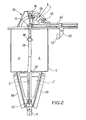
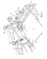
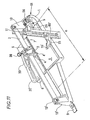
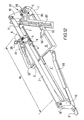
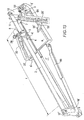
- a machine tile-cutter end 01 providing the tile scoring and cutting, physically and functionally extensible to cutting lengths within half metre, (figures 1 and 11) and one metre (figure 13) comprises, conventionally, a frame 1, made of light alloy, including two pieces 1', 1" (figure 7).
- the frame 1 has two uprights 10, 10' emerging at its ends. Said uprights 10, 10' hold at their upper ends a bridge-like guide 2.
- the bridge-like guide 2 shiftably receives therealong a tool carrier 30.
- the tool carrier 30 is provided, at its bottom, with a disc-like tool 3, and comprises also a cutting or rupturing tool in the form of a pair of fins 4', 4".
- the machine comprises a gauge 5, which is provided with a journal 50, a goniometer 05 and its fastening 56.
- the gauge 5 includes a small reference square 55, per se known and the frame 1 comprises resiliently suspended plates 6 and 6'.
- the machine comprises, in combination, a push-operable tool carrier member 30 and an operative station 11, placed at the end of the stroke of the tool carrier 30, i.e. substantially at the base of upright 10 which supports the guide 2 of the tool carrier 30.
- This operative station 11 terminates the wedge-like relief 7, which provides a reaction to scoring and cutting.
- the guide 2, which directs the tool carrier 30 is in the form of bridge. It is stationary and held by the uprights 10, 10' of the frame 1. It is exactly parallel to the reaction means 7.
- Such reaction means 7 react to the scoring push and to the cutting impact, which are reciprocally complementary.
- the gauge 5 which is of the swinging kind, has the reference centre, for the cutting of the tile 0, which is coaxial to the axis of the guide 2.
- the gauge 5 has its swinging centre 50 placed in a position which is some millimetres within a quadrant which is included by the axes of the bridge-like guide 2 and the adjacent side of the tile-rest plate 6 for the tile 0.
- the arrangement is such that, the vertical plane of rest and reference for the tile 0, stands substantially at the end of the reaction wedge-like relief 7, which, in turn, stands at a distance d ⁇ D from the front of the upright 10 or from the engaging point of the leading section 34", of the tool carrier 30.
- Such engaging point is provided by the same roller or wheel 34, which rolls against the base 2' of the guide 2 and provides, with its tangent f, the fulcrum of the second class lever, comprised by the tool carrier 30.
- the lever weights R d , Rp are provided, in turn, respectively, by the disc-like tool 3 and by the presser fins 4, 4'.
- the lever weight arms are, respectively comprised by the distance dd from the fulcrum f to the disc-like tool 3.and by the distance from the fulcrum f to the pressers pins 4, 4'.
- the lever power arm bp is comprised by the distance from the fulcrum f to the end 30' of the driving arm of the tool carrier 30, wherein the distance Of from the fulcrum f to the leading point 34"of the tool carrier 30 or engaging point, more the cutting weight arm br, is longer, by at least 2 cm, than the distance d comprised from the wedge-like relief 7 to the passive engaging point 134 of the upright 10, i.e.:
- the tile cutter end device comprises, in combination, a push-operable tool carrier 30, an operative station 11, a gauge 5 to comply with excursion requirements in various directions and with maximization of the distance comprised from the contour line of the tile 0 to the point wherein the pressure is applied.
- the distance comprised from the leading end 34" of the tool carrier 30, to the disc-like tool 3 is maximized as well.
- Such leading end 34" is comprised by the small roller or wheel 34, acting as a fulcrum f, against the bottom side of the bridge-like guide 2.
- the bottom side of the bridge-like guide 2 is kept parallel over the base 1, at a distance of 45 mm from the crest of the wedge-like relief 7, which is the means reacting to the scoring and cutting stresses.
- the disc-like tool 3 has a scoring weight arm which is of about 30 mm.
- the power arm of the second class lever is 36 cm long, and at parity of power arm, the cutting weight arm is of mm 90, whereby the cutting pressers 4, 4', provide the cutting pressure on the tile 0, at a distance of 100 mm from the upright 10, i.e., at least 22 mm inside of the contour line 0', of the tile 0; corresponding to 32 mm inside of the corner 0", when the tile is placed at 45 0 .
- the wedge-like means 7, providing the cutting reaction, are placed at a distance comprised within 65 and 125 mm from the upright 10 at the end of the scoring stroke of tile 0.
- Adapted means 5 are provided to clearly display the position of the tile 0 and of the sections to be cut and to render the cutting of small sections, parallel to the sides and in diagonal, possible.
- the push-operable tool carrier 30 comprises spring means 8, 8', adapted to support the tool carrier 30.
- Said spring means 8, 8' are comprised by two spiral springs 8, 8', which subtend, in the way of a second class pulley, a small roller 80, which comprises the same tool carrier hanging member 30.
- a reaction is provided therein, whereby the fulcrum f ,of the tool carrier 30, engages the base 2', of the bridge-like guide 2 and determines the landing of the cutting fins 4, 4' against the upper surface of the tile 0, exactly at the operative station 11.
- the arrangement of push-operable tool carrier 30, is such that, all over the coarse of the scoring, its driving end 30', in any working position, stands upright of the machine base 1. Whereas, on cutting, the same lever driving end 30', stands at a distance of at least 33 cm from the nearest end 10".
- the aforesaid and following parameters and particularly the distance of 45 mm from the base 2' of the bridge-like guide 2 (fixed and rigid) to the crest 7 engaging the tile provides enough room for receiving and working, by scoring and cutting, tiles having a thickness within 3 and 25 mm, without any adjusting.
- the tool carrier 30, is provided with a sufficient stroke, to cover the whole field of tile thickness (within 3 and 25 mm).
- the tool carrier 30 is provided with a screw adjuster 38, which may be optionally used, to limit the stroke to an interval congruous to the thickness of the tile.
- This screw adjuster 38 may be set each time that the thickness of the tile is changed. Such setting may be made simply, by getting the pressers 4, 4' engaged with the upper side of the tile, by putting the screw end 38', of the adjuster 38 in touch of tangency with the small roller 80 and finally retracting the latter of a fraction of round (e.g. within 1/4 of round and 1 round).
- the swingable gauge 5 in order to comply with excursion in useful directions and in order to maximize the distance comprised from the contour line 0' of the tile 0 to the point wherein the cutting pressure is applied, has its hinging centre 50 positioned at a distance of 13 mm, towards the front side of the machine, where the gauge 5 projects more with respect to the centre line of the plane of the bridge-like guide 2. It is advanced of the same distance, with respect to the line of alignment of the gauge 5, of the tile-rest planes 6, 6' and of the wedge-like relief 7. Above the swinging centre 50, the swingable gauge 5 includes a small pool 11', to provide a space for giving free movement to the disc-like tool 3.
- the small pool 11' is delimited, towards the tile 0, by a narrow ridge 12 which provides a side rest for the same tile 0.
- Said ridge 12 comprises a notch 12', which provides an indication of the point wherein, the corner 0" of the tile 0, set diagonally, is to be placed, to coincide with the running plane of the disc-like tool 3.
- the swingable gauge 5 is also provided with a cylindrical guide 05', comprising even an hinge for the small orthogonal square 55, which thus may be swung by 180 0 .
- the small orthogonal square 55 with its side 55' provides a tile side rest which is thinned as the thickness of the thinnest tile to be worked e.g., 3 mm, along a section corresponding to the minimum width which may be cut, or to the difference of dimensions between the latter and the width of cutting fin 4'.
- the operative station 11 comprises, at both sides of the reaction cutting wedge-like relief 7, the holes 70, for getting clear from tile fragments or chips, which could encumber the various parts which have to match.
- the cutting machine is provided with a pedal 9, which may be positioned and trampled by the operator, to keep it stationary upon scoring (figures 1, 2, 3, 6, 7, 11, 12, 13,).
- the machine is provided with an anti-slipping device 90 of the "sealskin" kind.
- This anti-slipping device 90 provides an opposition to the component of the scoring push applied on the tool carrier attending to slip the whole machine. It comprises a multitude of lamellae, having triangular cross section, wherein the side facing the operator, forms, with the bottom of the machine, an acute angle, while the opposed side, forms with the same bottom of the machine, an obtuse angle.
- the device has substantially nature of elastomeric body, which is, as said, lamelled and made of elastomeric material, having a very high coefficient of grip. However, its rigidity, is sufficient to determine, with the push, a trend to lift the machine (figure 14).
- the body 1 of the machine is comprised by two pieces 1', 1. These two pieces 1', 1" are directly provided by melting, with intercoupling sections ready for being assembled by screws. At least one of the machine body sections 1', 1" is provided with at least one tile supporting arm 99, 99', having a swinging angle of about 100o with working and rest position.
- the gauge 5, which is applied to the end device has, from the operator's side a constant extension of 20 cm, while from the opposite side has an extension respectively of 35, 45, 55 cm, according to the machine length.
- the suspensions of the plates 6 and 6' are provided by pads 60 of foamed material, which have their main surfaces provided with double face adhesive tape.
Landscapes
- Engineering & Computer Science (AREA)
- Mechanical Engineering (AREA)
- Mining & Mineral Resources (AREA)
- Processing Of Stones Or Stones Resemblance Materials (AREA)
- Mechanical Treatment Of Semiconductor (AREA)
- Apparatuses For Bulk Treatment Of Fruits And Vegetables And Apparatuses For Preparing Feeds (AREA)
- Finish Polishing, Edge Sharpening, And Grinding By Specific Grinding Devices (AREA)
- Sawing (AREA)
Applications Claiming Priority (2)
| Application Number | Priority Date | Filing Date | Title |
|---|---|---|---|
| ITVA930002 | 1993-01-18 | ||
| IT93VA000002A IT1265977B1 (it) | 1993-01-18 | 1993-01-18 | Testata di macchina tagliapiastrelle accentrante le funzioni di incisione e di taglio, fisicamente e funzionalmente estensibile a |
Publications (3)
| Publication Number | Publication Date |
|---|---|
| EP0608476A2 true EP0608476A2 (de) | 1994-08-03 |
| EP0608476A3 EP0608476A3 (en) | 1994-08-24 |
| EP0608476B1 EP0608476B1 (de) | 1998-12-30 |
Family
ID=11423219
Family Applications (1)
| Application Number | Title | Priority Date | Filing Date |
|---|---|---|---|
| EP93113611A Expired - Lifetime EP0608476B1 (de) | 1993-01-18 | 1993-08-25 | Fliessenschneidmaschine |
Country Status (5)
| Country | Link |
|---|---|
| EP (1) | EP0608476B1 (de) |
| AT (1) | ATE175144T1 (de) |
| DE (1) | DE69322848T2 (de) |
| ES (1) | ES2128374T3 (de) |
| IT (1) | IT1265977B1 (de) |
Cited By (10)
| Publication number | Priority date | Publication date | Assignee | Title |
|---|---|---|---|---|
| GB2329144A (en) * | 1997-09-13 | 1999-03-17 | Turner Intellect Property Ltd | Tile cutting apparatus |
| US6148810A (en) * | 1997-09-13 | 2000-11-21 | Plasplugs Inc. | Cutting/Breaking apparatus |
| WO2004030883A1 (en) * | 2002-10-01 | 2004-04-15 | Brevetti Montolit S.P.A. | Improved manual tile-cutting machine |
| CN101456221B (zh) * | 2008-11-20 | 2013-01-02 | 杭州一楠五金工具有限公司 | 手动瓷砖切割机专用手柄 |
| CN101456220B (zh) * | 2008-11-20 | 2013-01-02 | 杭州一楠五金工具有限公司 | 手动瓷砖切割机 |
| IT202200001715A1 (it) | 2022-02-01 | 2023-08-01 | Brevetti Montolit S P A | Tagliapiastrelle manuale perfezionata |
| IT202200018396A1 (it) | 2022-09-09 | 2024-03-09 | Brevetti Montolit S P A | Portautensile per una tagliapiastrelle manuale dotato di troncatore perfezionato |
| IT202300000075A1 (it) | 2023-01-05 | 2024-07-05 | Brevetti Montolit S P A | Tagliapiastrelle e mezzi di articolazione perfezionati per detta tagliapiastrelle |
| IT202300001176A1 (it) | 2023-01-26 | 2024-07-26 | Brevetti Montolit S P A | Sistema di sospensione per tagliapiastrelle |
| WO2024157116A1 (en) * | 2023-01-26 | 2024-08-02 | Brevetti Montolit S.P.A. | Suspension system for tile cutting machines |
Families Citing this family (6)
| Publication number | Priority date | Publication date | Assignee | Title |
|---|---|---|---|---|
| DE202010005474U1 (de) | 2010-05-21 | 2010-07-22 | Englhard, Hermann | Fliesenschneider |
| DE202012103508U1 (de) | 2012-09-14 | 2012-09-27 | Hermann Englhard | Fliesenschneider |
| DE202014101020U1 (de) | 2014-03-07 | 2014-04-04 | Hermann Englhard | Fliesenschneider |
| CN106182465B (zh) * | 2016-08-31 | 2017-12-19 | 天津大学 | 一种手动式瓷砖切割机 |
| DE102022003471A1 (de) | 2022-09-21 | 2024-03-21 | Thomas Bauer | Fliesenschneider |
| DE202022002090U1 (de) | 2022-09-21 | 2022-10-25 | Thomas Bauer | Fliesenschneider |
Family Cites Families (4)
| Publication number | Priority date | Publication date | Assignee | Title |
|---|---|---|---|---|
| FR1139167A (fr) * | 1955-12-30 | 1957-06-26 | Machine à couper les carreaux de faïence, grès, céramiques et ciment | |
| CH384787A (de) * | 1961-05-30 | 1965-02-26 | Courvoisier Jean Pierre | Vorrichtung zum Anritzen und/oder Trennen von flachem Schnittgut |
| IT8360940V0 (it) * | 1983-10-07 | 1983-10-07 | Cantecno Srl | Macchina leggerissima e maneggevole per il taglio di piastrelle piccole e medie particolarmente per dilettanti. |
| IT1247658B (it) * | 1990-12-31 | 1994-12-28 | Montolit Brevetti | Serie di macchine manuali, professionali,mediograndi,per il taglio di piastrelle durissime. |
-
1993
- 1993-01-18 IT IT93VA000002A patent/IT1265977B1/it active IP Right Grant
- 1993-08-25 AT AT93113611T patent/ATE175144T1/de not_active IP Right Cessation
- 1993-08-25 DE DE69322848T patent/DE69322848T2/de not_active Expired - Lifetime
- 1993-08-25 EP EP93113611A patent/EP0608476B1/de not_active Expired - Lifetime
- 1993-08-25 ES ES93113611T patent/ES2128374T3/es not_active Expired - Lifetime
Cited By (13)
| Publication number | Priority date | Publication date | Assignee | Title |
|---|---|---|---|---|
| GB2329144A (en) * | 1997-09-13 | 1999-03-17 | Turner Intellect Property Ltd | Tile cutting apparatus |
| US6148810A (en) * | 1997-09-13 | 2000-11-21 | Plasplugs Inc. | Cutting/Breaking apparatus |
| GB2329144B (en) * | 1997-09-13 | 2002-12-18 | Turner Intellect Property Ltd | Cutting/breaking apparatus |
| WO2004030883A1 (en) * | 2002-10-01 | 2004-04-15 | Brevetti Montolit S.P.A. | Improved manual tile-cutting machine |
| CN101456221B (zh) * | 2008-11-20 | 2013-01-02 | 杭州一楠五金工具有限公司 | 手动瓷砖切割机专用手柄 |
| CN101456220B (zh) * | 2008-11-20 | 2013-01-02 | 杭州一楠五金工具有限公司 | 手动瓷砖切割机 |
| IT202200001715A1 (it) | 2022-02-01 | 2023-08-01 | Brevetti Montolit S P A | Tagliapiastrelle manuale perfezionata |
| EP4219110A1 (de) | 2022-02-01 | 2023-08-02 | Brevetti Montolit S.P.A. | Manuelle fliesenschneidmaschine |
| EP4470741A3 (de) * | 2022-02-01 | 2025-02-19 | Brevetti Montolit S.P.A. | Verbesserte manuelle fliesenschneidmaschine |
| IT202200018396A1 (it) | 2022-09-09 | 2024-03-09 | Brevetti Montolit S P A | Portautensile per una tagliapiastrelle manuale dotato di troncatore perfezionato |
| IT202300000075A1 (it) | 2023-01-05 | 2024-07-05 | Brevetti Montolit S P A | Tagliapiastrelle e mezzi di articolazione perfezionati per detta tagliapiastrelle |
| IT202300001176A1 (it) | 2023-01-26 | 2024-07-26 | Brevetti Montolit S P A | Sistema di sospensione per tagliapiastrelle |
| WO2024157116A1 (en) * | 2023-01-26 | 2024-08-02 | Brevetti Montolit S.P.A. | Suspension system for tile cutting machines |
Also Published As
| Publication number | Publication date |
|---|---|
| ES2128374T3 (es) | 1999-05-16 |
| DE69322848T2 (de) | 2000-06-29 |
| ATE175144T1 (de) | 1999-01-15 |
| ITVA930002A0 (it) | 1993-01-18 |
| ITVA930002A1 (it) | 1994-07-18 |
| EP0608476B1 (de) | 1998-12-30 |
| IT1265977B1 (it) | 1996-12-16 |
| EP0608476A3 (en) | 1994-08-24 |
| DE69322848D1 (de) | 1999-02-11 |
Similar Documents
| Publication | Publication Date | Title |
|---|---|---|
| EP0608476B1 (de) | Fliessenschneidmaschine | |
| US20080052938A1 (en) | Construction layout and angle measurement tool | |
| CN213162844U (zh) | 一种机械用钢筋切割装置 | |
| US5596809A (en) | Circle cutter for drywall with measure guide | |
| EP0565561B1 (de) | Fliesenschneidevorrichtung | |
| US3871079A (en) | Cutting guide and board assembly | |
| US4868989A (en) | Wallpaper border cutter device | |
| US20220371223A1 (en) | Low-dust cutting device for multiple tiles and low-dust scoring device for concrete masonry units | |
| EP0537506B1 (de) | Werkzeugträger für eine Fliesenschneidvorrichtung | |
| EP1545849B9 (de) | Handbetätigte fliesenschneidvorrichtung | |
| EP1268146B1 (de) | Tragbare schneidvorrichtung mit höhenverstellbarem schneidwerkzeug zum ausführen von schnitten parallel zu einer referenzfläche | |
| CN212427962U (zh) | 一种方便的建筑施工用辅助装置 | |
| US20240208095A1 (en) | Portable Cutting Device To Cut A Workpiece | |
| CN113478603A (zh) | 一种木材刨片机端刀安装用防位置偏移分切切刀 | |
| CN116749360B (zh) | 石膏板切割装置 | |
| CN218083202U (zh) | 一种建筑材料加工用的切割装置 | |
| CN220612138U (zh) | 一种钢筋定位切割装置 | |
| CN217727343U (zh) | 一种窗框压板裁切机 | |
| CN219095318U (zh) | 一种便于施力均匀的模切板 | |
| CN216680002U (zh) | 一种电容器引线裁剪设备 | |
| CN217556066U (zh) | 一种用于室内装修建筑材料切割装置 | |
| JPH0611706Y2 (ja) | ジグソー | |
| CN214109003U (zh) | 一种具有宽度调节功能的分条机刀架 | |
| CN214561623U (zh) | 一种木材加工用夹持装置 | |
| CN213764938U (zh) | 一种建筑工地用建筑物料切割装置 |
Legal Events
| Date | Code | Title | Description |
|---|---|---|---|
| PUAI | Public reference made under article 153(3) epc to a published international application that has entered the european phase |
Free format text: ORIGINAL CODE: 0009012 |
|
| PUAL | Search report despatched |
Free format text: ORIGINAL CODE: 0009013 |
|
| AK | Designated contracting states |
Kind code of ref document: A2 Designated state(s): AT DE ES FR GB IT PT |
|
| AK | Designated contracting states |
Kind code of ref document: A3 Designated state(s): AT DE ES FR GB IT PT |
|
| 17P | Request for examination filed |
Effective date: 19941222 |
|
| 17Q | First examination report despatched |
Effective date: 19950328 |
|
| GRAG | Despatch of communication of intention to grant |
Free format text: ORIGINAL CODE: EPIDOS AGRA |
|
| GRAG | Despatch of communication of intention to grant |
Free format text: ORIGINAL CODE: EPIDOS AGRA |
|
| GRAH | Despatch of communication of intention to grant a patent |
Free format text: ORIGINAL CODE: EPIDOS IGRA |
|
| GRAH | Despatch of communication of intention to grant a patent |
Free format text: ORIGINAL CODE: EPIDOS IGRA |
|
| GRAA | (expected) grant |
Free format text: ORIGINAL CODE: 0009210 |
|
| AK | Designated contracting states |
Kind code of ref document: B1 Designated state(s): AT DE ES FR GB IT PT |
|
| PG25 | Lapsed in a contracting state [announced via postgrant information from national office to epo] |
Ref country code: AT Free format text: LAPSE BECAUSE OF FAILURE TO SUBMIT A TRANSLATION OF THE DESCRIPTION OR TO PAY THE FEE WITHIN THE PRESCRIBED TIME-LIMIT Effective date: 19981230 |
|
| REF | Corresponds to: |
Ref document number: 175144 Country of ref document: AT Date of ref document: 19990115 Kind code of ref document: T |
|
| REF | Corresponds to: |
Ref document number: 69322848 Country of ref document: DE Date of ref document: 19990211 |
|
| ITF | It: translation for a ep patent filed | ||
| PG25 | Lapsed in a contracting state [announced via postgrant information from national office to epo] |
Ref country code: PT Free format text: LAPSE BECAUSE OF FAILURE TO SUBMIT A TRANSLATION OF THE DESCRIPTION OR TO PAY THE FEE WITHIN THE PRESCRIBED TIME-LIMIT Effective date: 19990330 |
|
| REG | Reference to a national code |
Ref country code: ES Ref legal event code: FG2A Ref document number: 2128374 Country of ref document: ES Kind code of ref document: T3 |
|
| EN | Fr: translation not filed | ||
| EN | Fr: translation not filed |
Free format text: BO 99/21 PAGES: 275, IL Y A LIEU DE SUPPRIMER: LA MENTION DE LA NON REMISE DE CETTE TRADUCTION. LA MENTION DE LA REMISE DE CETTE TRADUCTION EST PUBLIEE DANS LE PRESENT BOPI. |
|
| ET | Fr: translation filed | ||
| PLBE | No opposition filed within time limit |
Free format text: ORIGINAL CODE: 0009261 |
|
| 26N | No opposition filed | ||
| REG | Reference to a national code |
Ref country code: FR Ref legal event code: ST |
|
| REG | Reference to a national code |
Ref country code: FR Ref legal event code: RN |
|
| REG | Reference to a national code |
Ref country code: FR Ref legal event code: D3 |
|
| REG | Reference to a national code |
Ref country code: GB Ref legal event code: IF02 |
|
| PGFP | Annual fee paid to national office [announced via postgrant information from national office to epo] |
Ref country code: DE Payment date: 20101101 Year of fee payment: 18 |
|
| PGFP | Annual fee paid to national office [announced via postgrant information from national office to epo] |
Ref country code: ES Payment date: 20110818 Year of fee payment: 19 Ref country code: FR Payment date: 20110907 Year of fee payment: 19 Ref country code: GB Payment date: 20110819 Year of fee payment: 19 |
|
| PGFP | Annual fee paid to national office [announced via postgrant information from national office to epo] |
Ref country code: IT Payment date: 20110825 Year of fee payment: 19 |
|
| GBPC | Gb: european patent ceased through non-payment of renewal fee |
Effective date: 20120825 |
|
| REG | Reference to a national code |
Ref country code: FR Ref legal event code: ST Effective date: 20130430 |
|
| PG25 | Lapsed in a contracting state [announced via postgrant information from national office to epo] |
Ref country code: IT Free format text: LAPSE BECAUSE OF NON-PAYMENT OF DUE FEES Effective date: 20120825 |
|
| PG25 | Lapsed in a contracting state [announced via postgrant information from national office to epo] |
Ref country code: GB Free format text: LAPSE BECAUSE OF NON-PAYMENT OF DUE FEES Effective date: 20120825 Ref country code: DE Free format text: LAPSE BECAUSE OF FAILURE TO SUBMIT A TRANSLATION OF THE DESCRIPTION OR TO PAY THE FEE WITHIN THE PRESCRIBED TIME-LIMIT Effective date: 20130301 |
|
| PG25 | Lapsed in a contracting state [announced via postgrant information from national office to epo] |
Ref country code: FR Free format text: LAPSE BECAUSE OF NON-PAYMENT OF DUE FEES Effective date: 20120831 |
|
| REG | Reference to a national code |
Ref country code: DE Ref legal event code: R119 Ref document number: 69322848 Country of ref document: DE Effective date: 20130301 |
|
| REG | Reference to a national code |
Ref country code: ES Ref legal event code: FD2A Effective date: 20131018 |
|
| PG25 | Lapsed in a contracting state [announced via postgrant information from national office to epo] |
Ref country code: ES Free format text: LAPSE BECAUSE OF NON-PAYMENT OF DUE FEES Effective date: 20120826 |