EP0608653A1 - Méthode et système pour le routage de l'information entre noeuds d'un réseau de communication - Google Patents
Méthode et système pour le routage de l'information entre noeuds d'un réseau de communication Download PDFInfo
- Publication number
- EP0608653A1 EP0608653A1 EP93480003A EP93480003A EP0608653A1 EP 0608653 A1 EP0608653 A1 EP 0608653A1 EP 93480003 A EP93480003 A EP 93480003A EP 93480003 A EP93480003 A EP 93480003A EP 0608653 A1 EP0608653 A1 EP 0608653A1
- Authority
- EP
- European Patent Office
- Prior art keywords
- node
- routing
- packets
- list
- route
- Prior art date
- Legal status (The legal status is an assumption and is not a legal conclusion. Google has not performed a legal analysis and makes no representation as to the accuracy of the status listed.)
- Withdrawn
Links
Images



Classifications
-
- H—ELECTRICITY
- H04—ELECTRIC COMMUNICATION TECHNIQUE
- H04L—TRANSMISSION OF DIGITAL INFORMATION, e.g. TELEGRAPHIC COMMUNICATION
- H04L45/00—Routing or path finding of packets in data switching networks
-
- H—ELECTRICITY
- H04—ELECTRIC COMMUNICATION TECHNIQUE
- H04L—TRANSMISSION OF DIGITAL INFORMATION, e.g. TELEGRAPHIC COMMUNICATION
- H04L45/00—Routing or path finding of packets in data switching networks
- H04L45/34—Source routing
Definitions
- the present invention relates to communication networks and more particularly to a method and a system for routing information between network nodes, which allow fast packet switches to be implemented and provide for network management facilities.
- Routing consists in finding the physical address of the communication link, on which a packet should be forwarded out of specific pieces of control information contained in the packet.
- Conventional routing methods are based on routing tables located in each node of a communication network, providing the physical address of the node output port to be used by a node input packet. Using such tables leads to a processing overhead which limits the throughput in network nodes. This drawback is eliminated by using routing techniques known as "self routing packets" in which the packets contain a list of the physical port address to be used by the successive nodes for switching the packets in order to route said packets within the network.
- each intermediate node reads the output port address to which the packet should be routed, at the beginning of the packet and deletes the port address which has been used within the node prior to transmitting the packet to the next node, as shown in Figure 1.
- intermediate nodes have no means to send notifications to the originator node of a packet in case of abnormal conditions (congestion, port outage, etc..)
- An object of the present invention is to provide a method and a system for routing packets in a node of a communication network in which routing of a packet on a given route can be performed either in the forward or backward direction, thereby allowing the node to react on the originator node of the packet.
- Another object of the present invention is to provide such a method and system in which the routing information is kept as compact as possible by means of a specific coding which optimizes the number of bits necessary for routing the packets.
- Another object of the present invention is to provide such a method and system allowing a node in the network to be able to contact and identify the neighboring nodes without any prior knowledge of the communication network topology.
- the method according to the present invention is used for routing packets from a first end node to a second end node in a communication network comprising a plurality of nodes having input/output ports, through which the packets are routed, and means for establishing a route to be followed by the packets sent from the first end node to the second end node, thereby identifying the nodes to be passed by the packets and in each node the ports through which the packets will enter the node and exit it, said input/output ports having port addresses.
- the method comprises the following steps:
- the combining step a) comprises the XORing of the input port address and output port address of each node of the route.
- it comprises the steps of associating a direction indicator (F/B) to the routing list and setting said indicator to a first value when the packets are sent in a forward direction from the first end node to the second end node and setting the indicator to a second value when feedback packets are returned in the reverse direction of the route, reading at each node the direction indicator of the packets received at an input port, reading at each node either the first routing code of the routing list if the direction indicator is set to the first value or the last routing code of the list if the direction indicator is set to the second value, XORing the routing code read from the routing list with the address of the input port, thereby obtaining the address of the output port, arranging the routing list by rotating the routing codes either forward if the direction indicator is set to the first value or backward if the direction indicator is set to the second value and passing the packets with the arranged routing list and direction indicator to the next node on the route.
- F/B direction indicator
- the present invention also relates to an apparatus for implementing the above described method.
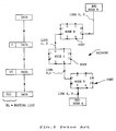
- Figure 1 represents a communication network and the routing lists which are associated to the data on the links between nodes on a route between two end nodes, according to the prior art.
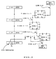
- Figure 2 represents a similar communication network with the routing lists associated to the data according to the subject invention for sending data in the forward direction between two end nodes.
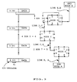
- Figure 3 represents the routing lists associated to the data according to the present invention for sending packets in the backward direction bewteen two end nodes.
- Figure 4 represents the routing lists associated to the data according to the present invention for sending a congestion notification packet.
- Figure 5 represents the format of the packets.
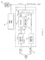
- Figure 6 schematically represents a node of the communication network.
- Figure 7 represents the block diagram of a link adapter of figure 6.
- Figure 8 represents the steps of the routing process implemented by the link adapters.
- Figure 9 represents a detailed implementation of a link adapter.
- Figure 1 schematically represents a communication network including several nodes, shown as nodes A, B, C, D, E.
- Information packets are transported through the network nodes, going from an end node for example A to another end node for example E.
- the set of links and intermediate nodes included between the two end nodes A and E characterize a specific route.
- the end nodes are provided with interfaces toward other network nodes referred to as intermediate nodes and interface toward end user terminals.
- Each node is provided with input/output ports shown as 0 to 7. Only the input/output ports of the intermediate nodes are shown in Figure 1.
- an information packet transmitted from node A to node E is headed by a routing list RL containing a list of the output port addresses to be used by nodes B,C,D to transport that packet to node E.
- each intermediate node reads the output port address in the RL list at the beginning of the packet, and it deletes the port address which has been used, prior to transmitting that packet to the next node.
- the prior art packet format is shown in Figure 1 for each link, A,B; B,C; C,D; D,E, of the route.
- This routing algorithm is very effective from a performance standpoint, however as explained in the background part of this description, the intermediate nodes have no means to send a notification to the end node originator of a packet, in case of abnormal condition, for instance when there is a port outage or when congestions occur.
- Figures 2 and 3 show the same network as figure 1, with the routing list for routing a packet in the forward and backward direction.
- the routing list RL which is associated to the packet is determined as follows:
- a node knows the input port address IPA from which a packet was received, the most condensed form of coding the routing list enabling a node to determine the output port OPA to which the packet should be routed is to build for each traversed node a routing code RC to be included in the routing list, such code being a combination of the input port and output port addresses of the node.
- the routing list is modified in each node in order to enable an intermediate node to retrieve the RC code to be used to route the packet, while keeping all the routing information contained in the packet header.
- Figure 2 shows the routing list on link B,C is 4,5,2, on link C,D it is 5,4,2 and on link D,E it is 2,4,5.
- An intermediate node can also send a notification back to the originator of a packet in the same way.
- Figure 2 shows a packet sent from node A to node E.
- a forward rotation of the routing list is performed prior to sending the packet to node C. The same operations take place in node C and D.
- Figure 3 shows a packet sent as a response from end node E to end node A.
- the same routing information is re-used except for the indicator F/B that is turned into 0.
- Node D selects its routing code at the end of the routing list which is rotated backward prior to sending the packet to the next node.
- Figure 4 illustrates how a congestion notification is sent by node D to end node A as a result of an excessive queue length at port 3 of node D.
- a notification CN in the data part of the packet is generated by node D.
- node D blanks its RC in the notification packet.
- this notification will end up in the management services of Node D where it can be logged.
- the mechanism allowing an intermediate node to generate a notification can be used for other purposes. It can be used to trace the progression of a packet though the network, to send an outage notification to an end node or to wrap test messages
- the packets contain a control field as shown in figure 5, containing different indicators: Forward/backward F/B Notify congestion Trace Wrap Feedback routing list length (3 bits)
- An intermediate node may return a congestion notification to the originator of a packet only if the congestion notification bit is on.
- An intermediate node will return a trace notification to the originator of a packet having the trace bit on, when this packet has been successfully routed.
- An intermediate node will return a packet, at the level of the link adaptor, if this wrap bit is on and if the Routing code RC in the RL list is equal to 0.
- the packet is comprised between flags and comprises the RL field, data and frame check sequence FCS fields.
- Figure 6 shows the basic structure of an intermediate node of the network. It is made of a collection of link adapters 60-1 to 60-n interconnected by a switch 62. It also comprises a network management adapter 64. Various kinds of switches can be used in such a node. In this description it will be assumed that the switch is made of a shared bus.
- the network management adapter is responsive to a network access request from one user, to provide the routing list to be appended to the packets for a destination user, as a function of the destination user address.
- Figure 7 shows the structure of a link adapter.
- Framing control in and framing control out circuits 70 and 72 perform the usual functions of a link adapter. They deal with the management of the serial bit input flow and output flow on in and out links 74 and 73. These functions are the detection and generation of the frame delimiting flags, insertion/deletion of zeroes, frame checking. These circuits will not be described in details since they are conventional circuits.
- the link adapter comprises a routing circuit 76, which processes the routing list. It is able to rotate the routing list RL in two ways: Forward: the bits of the first routing code are moved at the end of the list. Backward: the bits of the last routing code are moved at the beginning of the list.
- a packet is fed back toward the source user. This is achieved by the feedback circuit 78, which provides the packet from output link 75 of framing control in circuit 70 on input link 77 of feed back circuit 78, so that the packet is provided on input link 79 of framing control out circuit.
- Bus interface circuit 82 is the interface between the link adapter and the bus 84.
- the bus accesses are managed by bus arbiter 86 which receives the bus requests from the link adapters of the node and grant the bus to a selected adapter, which thus gains access to the bus for sending data packets.
- Routing circuit 76 implements the process shown in Figure 8.
- routing circuit 76 reads the control field C of the packet; Then, it tests at step 92, the F/B indicator. If this bit is set to 1, (forward), it reads the first RC code at the beginning of RL (step 94). If this bit is set to 0 (backward), it reads the last RC at the end of the routing list RL (step 96). Then, it tests (step 98) the RC code. If it is found equal to 0, it tests the wrap bit "3" in the control field at step 100. If this bit is set to 1, it enable the feedback of the packet through circuit 82 (step 101).
- wrap bit is equal to 0, a request for the bus access is raised to adapter (address 0), i.e. node management adapter 64, at step 102, and then when the bus access is granted it transfers the packet to the node management adapter 64, at step 104.
- adapter address 0
- node management adapter 64 i.e. node management adapter 64
- the addressed adapter responds with a status indicating whether a congestion exists on this output link. This indication is used to format a feedback packet reporting the congestion situation. If this situation exists and if bit "1" is equal to 1, it enables a feedback congestion notification (step 112).
- bit "2" is equal to 1 it enables a feedback trace (step 114).
- the bus When the bus is granted, it arranges the routing list and transfers the packet to adapter with address OPA, step 116.
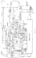
- routing circuit 76 and feedback circuit 77 The detailed implementation of the routing circuit 76 and feedback circuit 77 is shown in figure 9.
- Framing control circuit 70 detects the flags in the received frames and activates RCV packet line 120 when the leading flag of a packet is detected.
- Line 120 is provided to a sequence control circuit 122 which generates gating signals on lines 124, 126, 128, 130, 132, 134, 136, 138, 140 and 142, to control the operation of the routing and feedback circuits.
- line 126 When RCV packet line is activated, line 126 is activated. It is provided to the input of AND gate 146, which receives on another input line 148, a receive clock signal RCLK and provides this signal on its output line 150, to the shift input of a FIFO register 152. As a result the packet bits provided by framing control IN circuit on link 75 to the data input of the FIFO register 152 are inputted in this register under control of the RCLK signal.
- RCLK signal on line 148 is also provided to one input of AND gate 154 which receives on another input 128 a gating signal from sequence control circuit 122 during 8-bit clock times of the RCV packet period. This provides the RCLK signal on the shift input 156 of C shift-register 160.
- the packet bits from link 75 are provided to the data input of C shift-register 160, and thus the C field of the packet is inputted into this register 160.
- Sequence control circuit 122 tests the various bits in the C field. Thus, it tests the F/B bit indicator, to activate GATE RC line 124 at the right time depending upon the value of this indicator, so as to gate the first RC code in the RL list or the last RC code in the RL list, as described in reference to figure 7.
- GATE RC line 124 is provided to one input of AND gate 162, the other input of which is the RCLK line to gate the RCLK signal on its output line 164 to the shift input of RC register 166.
- the bit packet from link 75 is provided to the data input of RC register 166.
- the first RC or last RC code is stored in register 166.
- the status signal indicates whether the last received packet is correct or not.
- the registers 152, 160 and 166 are reset and wait for the next packet. If the packet is correct, the routing process takes place.
- register RC The contents of register RC is provided to a "all 0" detector 170 which activates its output line 172 when the RC code in register 166 is "all 0" in which case the packet is destined to this node.
- the OPA address is generated by XOR circuit 174, which provides the XOR function of the RC contents and IPA port address stored in register 176, and generates the OPA address on bus 178 to bus interface circuit 82.
- bus interface circuit When the connection with the link adapter to which the packet is to be sent is granted, bus interface circuit provides a BUS clock signal on BCLK line 180 and activates grant line 83-G. This clock signal is used to pump the packet including an arranged routing list out of the routing logic.
- Arranging the routing list RL is performed by FIFO register 182 by FIFO register 182, according to the value of the F/B bit tested by sequence control circuit 122.
- AND gate 184 is open by a gating signal from line 136 to gate the contents of FIFO 152 provided from line 190 on output line 192 under control of the BCLK signal which is provided to FIFO register 152 by AND gate 196, when conditioned by a signal from line 198 meaning that the packet is to be sent to interface circuit 82, (no wrap).
- AND gate 196 provides the BCLK signal on a shift input 200 of FIFO register 152, which causes the bits stored in FIFO 152 to be provided on data output line 190 under control of the BCLK signal.
- AND gate 186 gates the BCLK signal from line 180 to FIFO 182 through line 194 at the right time as determined by gating signal from line 134 to copy the RC code determined by the sequence control circuit 122 into FIFO 182 when it is outputted from FIFO register 152 on line 190.
- BCLK signal is provided to AND gate 188 and when this gate is open by a signal from line 142, the BCLK is provided to FIFO register 182 to pump the RC bits stored in this register and provide them on data output line 204.
- the lines 192 and 204 are provided to OR gate 206 which merges the bit streams from FIFO registers 152 and 182 on its output line 208.
- RC register 166 If the code contained in RC register 166 is "all 0" and when no local wrap is requested as indicated by the wrap bit in C register 160, the access to the bus is requested and the packet is provided on line 208 without rotating the routing list. The packet is entirely transferred through gates 184 and OR gate 206. XOR circuit 174 is inhibited, so as to provide a "0" address on bus 178, to route the packet to the node management adapter 64.
- the packet bits are provided on line 208, they are accompanied by a strobe signal on line 183 provided by AND gate 181.
- AND gate 181 is open by a data out gating signal from sequence control circuit 122, on line 179 and gates the BCLK signal from line 180 on strobe line 183.
- Any packet sent back to the originator is forwarded through FIFO register 212.
- the feedback packet is generated and the sequence control circuit 122 formats and loads the C field into register 160 through bus 130.
- the C field is transferred into FIFO register 212 through OR gate 214 and under control of the BCLK signal provided on line 216 through AND gate 218 open by a gating signal on line 140 and under the control of the B clock signal provided to C register 160 through AND gate 158 open by a gating signal on line 132.
- the RL code is transferred without rotation from FIFO register 152 into FIFO register 212 through AND gate 220 open by gating signal on line 128, which is used to blank the RC code either at the beginning or at the end of the RL list depending upon the value of the F/B indicator.
- any further status sent after RL is loaded through C register 160.
- the framing control out logic When the framing control out logic is ready to accept the feedback packet for transmission, it provides a transmit clock signal on XCLK line 222, which pumps the feedback packet cut of FIFO register 212.
- the routing process according to the invention is not based on node addresses. Therefore node addresses do not appear in the subject description. However node addresses are used in a end to end communication protocol between two end nodes. This protocol which is conventional is not described here.
- An alternative to the rotation of the routing list would consist in providing an index pointing at the RC that a node must use, this index being incremented of decremented by the routing process.
Landscapes
- Engineering & Computer Science (AREA)
- Computer Networks & Wireless Communication (AREA)
- Signal Processing (AREA)
- Data Exchanges In Wide-Area Networks (AREA)
Priority Applications (3)
| Application Number | Priority Date | Filing Date | Title |
|---|---|---|---|
| EP93480003A EP0608653A1 (fr) | 1993-01-26 | 1993-01-26 | Méthode et système pour le routage de l'information entre noeuds d'un réseau de communication |
| US08/163,106 US5477536A (en) | 1993-01-26 | 1993-12-07 | Method and system for routing information between nodes in a communication network |
| JP33311793A JP2572541B2 (ja) | 1993-01-26 | 1993-12-27 | パケットのルーティング方法及び装置 |
Applications Claiming Priority (1)
| Application Number | Priority Date | Filing Date | Title |
|---|---|---|---|
| EP93480003A EP0608653A1 (fr) | 1993-01-26 | 1993-01-26 | Méthode et système pour le routage de l'information entre noeuds d'un réseau de communication |
Publications (1)
| Publication Number | Publication Date |
|---|---|
| EP0608653A1 true EP0608653A1 (fr) | 1994-08-03 |
Family
ID=8214818
Family Applications (1)
| Application Number | Title | Priority Date | Filing Date |
|---|---|---|---|
| EP93480003A Withdrawn EP0608653A1 (fr) | 1993-01-26 | 1993-01-26 | Méthode et système pour le routage de l'information entre noeuds d'un réseau de communication |
Country Status (3)
| Country | Link |
|---|---|
| US (1) | US5477536A (fr) |
| EP (1) | EP0608653A1 (fr) |
| JP (1) | JP2572541B2 (fr) |
Cited By (4)
| Publication number | Priority date | Publication date | Assignee | Title |
|---|---|---|---|---|
| GB2302236A (en) * | 1995-06-09 | 1997-01-08 | Samsung Electronics Co Ltd | Packet transmission path search |
| EP0725523A3 (fr) * | 1995-01-05 | 1997-08-06 | Ibm | Acheminement de messages de transaction dans un réseau numérique de communication |
| GB2320159A (en) * | 1996-10-02 | 1998-06-10 | Ibm | Aggregate Inernet route switching |
| WO1999005800A1 (fr) * | 1997-07-23 | 1999-02-04 | Motorola Inc. | Codes d'etalement multiples dans des systemes de communications par satellites |
Families Citing this family (39)
| Publication number | Priority date | Publication date | Assignee | Title |
|---|---|---|---|---|
| US5668800A (en) * | 1994-05-02 | 1997-09-16 | International Business Machines Corporation | Path testing in communications networks |
| JP3045050B2 (ja) * | 1995-08-08 | 2000-05-22 | トヨタ自動車株式会社 | 送信位置検出方法、通信システム及び中継装置 |
| JP3382769B2 (ja) * | 1996-02-15 | 2003-03-04 | 日本電気株式会社 | 性能監視機能付き伝送装置 |
| US5652751A (en) * | 1996-03-26 | 1997-07-29 | Hazeltine Corporation | Architecture for mobile radio networks with dynamically changing topology using virtual subnets |
| US5768271A (en) * | 1996-04-12 | 1998-06-16 | Alcatel Data Networks Inc. | Virtual private network |
| US5754543A (en) * | 1996-07-03 | 1998-05-19 | Alcatel Data Networks, Inc. | Connectivity matrix-based multi-cost routing |
| US5896379A (en) * | 1996-08-26 | 1999-04-20 | Motorola, Inc. | Network node for packet switching with selective data processing and method therefor |
| JP3697831B2 (ja) * | 1997-04-18 | 2005-09-21 | 株式会社日立製作所 | コンピュータシステム |
| US6041049A (en) * | 1997-05-06 | 2000-03-21 | International Business Machines Corporation | Method and apparatus for determining a routing table for each node in a distributed nodal system |
| US6178448B1 (en) * | 1997-06-18 | 2001-01-23 | International Business Machines Corporation | Optimal link scheduling for multiple links by obtaining and utilizing link quality information |
| US6072797A (en) * | 1997-07-31 | 2000-06-06 | International Business Machines Corporation | Methods, apparatus and computer program products for aggregated transmission groups in high speed networks |
| US6912222B1 (en) | 1997-09-03 | 2005-06-28 | Internap Network Services Corporation | Private network access point router for interconnecting among internet route providers |
| US6009081A (en) * | 1997-09-03 | 1999-12-28 | Internap Network Services | Private network access point router for interconnecting among internet route providers |
| US6633570B1 (en) * | 1999-02-08 | 2003-10-14 | Paitalk Holdings, Inc. | Efficient transmission of data to multiple network nodes |
| CA2383092A1 (fr) * | 1999-08-16 | 2001-02-22 | John Carlson | Routeur de point d'acces de reseau prive servant a la connexion entre fournisseurs de route internet |
| GB2354914B (en) * | 1999-09-29 | 2003-10-22 | Ibm | Data processing technique for message tracing in an asynchronous messaging network |
| US7123620B1 (en) * | 2000-04-25 | 2006-10-17 | Cisco Technology, Inc. | Apparatus and method for scalable and dynamic traffic engineering in a data communication network |
| US7111163B1 (en) | 2000-07-10 | 2006-09-19 | Alterwan, Inc. | Wide area network using internet with quality of service |
| US7720959B2 (en) | 2000-10-17 | 2010-05-18 | Avaya Inc. | Method and apparatus for characterizing the quality of a network path |
| US7406539B2 (en) | 2000-10-17 | 2008-07-29 | Avaya Technology Corp. | Method and apparatus for performance and cost optimization in an internetwork |
| US7363367B2 (en) | 2000-10-17 | 2008-04-22 | Avaya Technology Corp. | Systems and methods for robust, real-time measurement of network performance |
| US7487237B2 (en) | 2000-10-17 | 2009-02-03 | Avaya Technology Corp. | Load optimization |
| ATE459154T1 (de) | 2000-10-17 | 2010-03-15 | Avaya Technology Corp | Verfahren und vorrichtung zur optimierung der leistung und des kosten in einem internetzwerk |
| US7336613B2 (en) | 2000-10-17 | 2008-02-26 | Avaya Technology Corp. | Method and apparatus for the assessment and optimization of network traffic |
| US8023421B2 (en) | 2002-07-25 | 2011-09-20 | Avaya Inc. | Method and apparatus for the assessment and optimization of network traffic |
| US7756032B2 (en) | 2000-10-17 | 2010-07-13 | Avaya Inc. | Method and apparatus for communicating data within measurement traffic |
| US7349994B2 (en) | 2000-10-17 | 2008-03-25 | Avaya Technology Corp. | Method and apparatus for coordinating routing parameters via a back-channel communication medium |
| US7080161B2 (en) * | 2000-10-17 | 2006-07-18 | Avaya Technology Corp. | Routing information exchange |
| US7899066B2 (en) * | 2001-01-25 | 2011-03-01 | Alcatel Lucent | Distributed intelligence MAC protocols for DWDM ring networks |
| US7078163B2 (en) * | 2001-03-30 | 2006-07-18 | Medtronic, Inc. | Process for reducing mineralization of tissue used in transplantation |
| DE60131551T2 (de) * | 2001-12-12 | 2008-10-23 | Alcatel Lucent | Telekommunikationsnetzwerk und entsprechenden Paketkopf |
| US20050010668A1 (en) * | 2003-07-07 | 2005-01-13 | Shiwen Chen | Traversable network address translation with hierarchical internet addressing architecture |
| US7955788B2 (en) * | 2003-10-30 | 2011-06-07 | Medtronic, Inc. | Bioprosthetic tissue preparation with synthetic hydrogels |
| US20050266390A1 (en) * | 2004-06-01 | 2005-12-01 | Yuichiro Ueda | Processes for removing cells and cell debris from tissue and tissue constructs used in transplantation and tissue reconstruction |
| US9577955B2 (en) * | 2013-03-12 | 2017-02-21 | Forrest Lawrence Pierson | Indefinitely expandable high-capacity data switch |
| US10171430B2 (en) | 2015-07-27 | 2019-01-01 | Forrest L. Pierson | Making a secure connection over insecure lines more secure |
| US10564969B2 (en) | 2015-12-03 | 2020-02-18 | Forrest L. Pierson | Enhanced protection of processors from a buffer overflow attack |
| US11675587B2 (en) | 2015-12-03 | 2023-06-13 | Forrest L. Pierson | Enhanced protection of processors from a buffer overflow attack |
| CN117135106B (zh) * | 2023-10-25 | 2024-02-13 | 苏州元脑智能科技有限公司 | 路由路径规划方法、路由请求处理方法、设备及介质 |
Citations (3)
| Publication number | Priority date | Publication date | Assignee | Title |
|---|---|---|---|---|
| WO1984000266A1 (fr) * | 1982-06-25 | 1984-01-19 | Western Electric Co | Agencement de memoire d'information d'une extremite a l'autre dans un controleur de ligne |
| EP0377360A1 (fr) * | 1988-12-15 | 1990-07-11 | Laboratoire Europeen De Recherches Electroniques Avancees | Procédé de routage de messages dans un réseau à plusieurs canaux de transmission différents |
| WO1992005648A1 (fr) * | 1990-09-19 | 1992-04-02 | Telefonaktiebolaget Lm Ericsson | Procede et dispositif d'adressage de destination et d'emetteur dans un reseau de commutation par paquets |
Family Cites Families (6)
| Publication number | Priority date | Publication date | Assignee | Title |
|---|---|---|---|---|
| JPS597276A (ja) * | 1982-07-05 | 1984-01-14 | Nippon Jidosha Seibi Shoko Kumiai Rengokai | 車載バツテリとその充電系統の診断装置 |
| CA1297567C (fr) * | 1987-02-06 | 1992-03-17 | Kazuo Hajikano | Systeme de commutation a acheminement automatique |
| US5367518A (en) * | 1987-10-15 | 1994-11-22 | Network Equipment Technologies, Inc. | Self-routing switching element and fast packet switch |
| US5115433A (en) * | 1989-07-18 | 1992-05-19 | Metricom, Inc. | Method and system for routing packets in a packet communication network |
| US4939726A (en) * | 1989-07-18 | 1990-07-03 | Metricom, Inc. | Method for routing packets in a packet communication network |
| US5309433A (en) * | 1992-06-18 | 1994-05-03 | International Business Machines Corp. | Methods and apparatus for routing packets in packet transmission networks |
-
1993
- 1993-01-26 EP EP93480003A patent/EP0608653A1/fr not_active Withdrawn
- 1993-12-07 US US08/163,106 patent/US5477536A/en not_active Expired - Lifetime
- 1993-12-27 JP JP33311793A patent/JP2572541B2/ja not_active Expired - Fee Related
Patent Citations (3)
| Publication number | Priority date | Publication date | Assignee | Title |
|---|---|---|---|---|
| WO1984000266A1 (fr) * | 1982-06-25 | 1984-01-19 | Western Electric Co | Agencement de memoire d'information d'une extremite a l'autre dans un controleur de ligne |
| EP0377360A1 (fr) * | 1988-12-15 | 1990-07-11 | Laboratoire Europeen De Recherches Electroniques Avancees | Procédé de routage de messages dans un réseau à plusieurs canaux de transmission différents |
| WO1992005648A1 (fr) * | 1990-09-19 | 1992-04-02 | Telefonaktiebolaget Lm Ericsson | Procede et dispositif d'adressage de destination et d'emetteur dans un reseau de commutation par paquets |
Cited By (10)
| Publication number | Priority date | Publication date | Assignee | Title |
|---|---|---|---|---|
| EP0725523A3 (fr) * | 1995-01-05 | 1997-08-06 | Ibm | Acheminement de messages de transaction dans un réseau numérique de communication |
| GB2302236A (en) * | 1995-06-09 | 1997-01-08 | Samsung Electronics Co Ltd | Packet transmission path search |
| GB2302236B (en) * | 1995-06-09 | 1997-06-11 | Samsung Electronics Co Ltd | Packet transmission seraching |
| GB2320159A (en) * | 1996-10-02 | 1998-06-10 | Ibm | Aggregate Inernet route switching |
| GB2320159B (en) * | 1996-10-02 | 2001-04-11 | Ibm | Aggregate internet route switching |
| WO1999005800A1 (fr) * | 1997-07-23 | 1999-02-04 | Motorola Inc. | Codes d'etalement multiples dans des systemes de communications par satellites |
| FR2767000A1 (fr) * | 1997-07-23 | 1999-02-05 | Motorola Inc | Procede et appareil utilisant des codes d'etalement multiples pour la transmission de donnees dans un systeme de telecommunications par satellites |
| GB2332829A (en) * | 1997-07-23 | 1999-06-30 | Motorola Inc | Multiple spreading codes in satellite communication systems |
| US5940379A (en) * | 1997-07-23 | 1999-08-17 | Motorola, Inc. | Apparatus and method for using multiple spreading codes for data transmission in a satellite communication system |
| GB2332829B (en) * | 1997-07-23 | 2002-04-24 | Motorola Inc | Multiple spreading codes in satellite communication systems |
Also Published As
| Publication number | Publication date |
|---|---|
| US5477536A (en) | 1995-12-19 |
| JPH06252951A (ja) | 1994-09-09 |
| JP2572541B2 (ja) | 1997-01-16 |
Similar Documents
| Publication | Publication Date | Title |
|---|---|---|
| US5477536A (en) | Method and system for routing information between nodes in a communication network | |
| US4561090A (en) | Integrated self-checking packet switch node | |
| US4500987A (en) | Loop transmission system | |
| US4688035A (en) | End user data stream syntax | |
| US5519693A (en) | High speed transmission line interface | |
| EP0164000B1 (fr) | Méthode et système pour l'acheminement de trames dans un réseau local à multiples anneaux | |
| JPS60148249A (ja) | メツセ−ジ除去方法 | |
| EP0409539B1 (fr) | Méthode de routage pour les trames de réseaux de communication | |
| EP0214593A2 (fr) | Commutateur de paquets en forme d'anneau | |
| EP0108554A1 (fr) | Surveillance de charge de paquets par des dispositifs de commande de ligne de jonction | |
| JPS60264143A (ja) | フレーム伝送方法 | |
| US5398235A (en) | Cell exchanging apparatus | |
| US5153920A (en) | Method and circuit arrangement for the acceptance and forwarding of message cells transmitted according to an asynchronous transfer mode by an asynchronous transfer mode switching equipment | |
| EP0537297B1 (fr) | Procede et dispositif d'adressage de destination et d'emetteur dans un reseau de commutation par paquets | |
| US5168496A (en) | System for internetwork communication between local areas networks | |
| US5572679A (en) | Multiprocessor system transferring abnormality detection signal generated in networking apparatus back to processor in parallel with data transfer route | |
| EP0756727B1 (fr) | Methode et dispositif de commande d'une memoire | |
| CA1270960A (fr) | Information non codee et mecanisme de commutation de donnees connexes | |
| JPS60149239A (ja) | 通信ネツトワ−クシステム | |
| JPH0653942A (ja) | メッセージ切換えシステムにおけるメッセージのエラー訂正コードを生成および検査する装置 | |
| US20080298381A1 (en) | Apparatus for queue management of a global link control byte in an input/output subsystem | |
| US6282203B1 (en) | Packet data transmitting apparatus, and method therefor | |
| GB2188216A (en) | Ring bus communications systems | |
| EP0557910B1 (fr) | Commutateur de cellules | |
| JPH0583287A (ja) | コネクシヨンレス通信トラヒツクの輻輳制御方式 |
Legal Events
| Date | Code | Title | Description |
|---|---|---|---|
| PUAI | Public reference made under article 153(3) epc to a published international application that has entered the european phase |
Free format text: ORIGINAL CODE: 0009012 |
|
| AK | Designated contracting states |
Kind code of ref document: A1 Designated state(s): DE FR GB |
|
| 17P | Request for examination filed |
Effective date: 19941125 |
|
| 17Q | First examination report despatched |
Effective date: 19971110 |
|
| RTI1 | Title (correction) |
Free format text: METHOD AND APPARATUS FOR ROUTING INFORMATION BETWEEN NODES IN A COMMUNICATION NETWORK |
|
| STAA | Information on the status of an ep patent application or granted ep patent |
Free format text: STATUS: THE APPLICATION IS DEEMED TO BE WITHDRAWN |
|
| 18D | Application deemed to be withdrawn |
Effective date: 20000701 |