EP0608750A1 - Teleskopierbare und verriegelbare Verbindungsgliedanordnung - Google Patents
Teleskopierbare und verriegelbare Verbindungsgliedanordnung Download PDFInfo
- Publication number
- EP0608750A1 EP0608750A1 EP94100636A EP94100636A EP0608750A1 EP 0608750 A1 EP0608750 A1 EP 0608750A1 EP 94100636 A EP94100636 A EP 94100636A EP 94100636 A EP94100636 A EP 94100636A EP 0608750 A1 EP0608750 A1 EP 0608750A1
- Authority
- EP
- European Patent Office
- Prior art keywords
- der
- daß
- eine
- die
- ein
- Prior art date
- Legal status (The legal status is an assumption and is not a legal conclusion. Google has not performed a legal analysis and makes no representation as to the accuracy of the status listed.)
- Granted
Links
Images

Classifications
-
- A—HUMAN NECESSITIES
- A01—AGRICULTURE; FORESTRY; ANIMAL HUSBANDRY; HUNTING; TRAPPING; FISHING
- A01B—SOIL WORKING IN AGRICULTURE OR FORESTRY; PARTS, DETAILS, OR ACCESSORIES OF AGRICULTURAL MACHINES OR IMPLEMENTS, IN GENERAL
- A01B59/00—Devices specially adapted for connection between animals or tractors and agricultural machines or implements
- A01B59/06—Devices specially adapted for connection between animals or tractors and agricultural machines or implements for machines mounted on tractors
- A01B59/061—Devices specially adapted for connection between animals or tractors and agricultural machines or implements for machines mounted on tractors specially adapted for enabling connection or disconnection controlled from the driver's seat
- A01B59/063—Devices specially adapted for connection between animals or tractors and agricultural machines or implements for machines mounted on tractors specially adapted for enabling connection or disconnection controlled from the driver's seat the connection comprising longitudinally oriented tang-and-sheath elements
-
- B—PERFORMING OPERATIONS; TRANSPORTING
- B60—VEHICLES IN GENERAL
- B60D—VEHICLE CONNECTIONS
- B60D1/00—Traction couplings; Hitches; Draw-gear; Towing devices
- B60D1/14—Draw-gear or towing devices characterised by their type
- B60D1/145—Draw-gear or towing devices characterised by their type consisting of an elongated single bar or tube
- B60D1/155—Draw-gear or towing devices characterised by their type consisting of an elongated single bar or tube comprising telescopic or foldable parts
-
- B—PERFORMING OPERATIONS; TRANSPORTING
- B60—VEHICLES IN GENERAL
- B60D—VEHICLE CONNECTIONS
- B60D1/00—Traction couplings; Hitches; Draw-gear; Towing devices
- B60D1/24—Traction couplings; Hitches; Draw-gear; Towing devices characterised by arrangements for particular functions
- B60D1/36—Traction couplings; Hitches; Draw-gear; Towing devices characterised by arrangements for particular functions for facilitating connection, e.g. hitch catchers
- B60D1/40—Traction couplings; Hitches; Draw-gear; Towing devices characterised by arrangements for particular functions for facilitating connection, e.g. hitch catchers involving a temporarily extensible or alignable member
-
- Y—GENERAL TAGGING OF NEW TECHNOLOGICAL DEVELOPMENTS; GENERAL TAGGING OF CROSS-SECTIONAL TECHNOLOGIES SPANNING OVER SEVERAL SECTIONS OF THE IPC; TECHNICAL SUBJECTS COVERED BY FORMER USPC CROSS-REFERENCE ART COLLECTIONS [XRACs] AND DIGESTS
- Y10—TECHNICAL SUBJECTS COVERED BY FORMER USPC
- Y10T—TECHNICAL SUBJECTS COVERED BY FORMER US CLASSIFICATION
- Y10T403/00—Joints and connections
- Y10T403/59—Manually releaseable latch type
- Y10T403/599—Spring biased manipulator
-
- Y—GENERAL TAGGING OF NEW TECHNOLOGICAL DEVELOPMENTS; GENERAL TAGGING OF CROSS-SECTIONAL TECHNOLOGIES SPANNING OVER SEVERAL SECTIONS OF THE IPC; TECHNICAL SUBJECTS COVERED BY FORMER USPC CROSS-REFERENCE ART COLLECTIONS [XRACs] AND DIGESTS
- Y10—TECHNICAL SUBJECTS COVERED BY FORMER USPC
- Y10T—TECHNICAL SUBJECTS COVERED BY FORMER US CLASSIFICATION
- Y10T403/00—Joints and connections
- Y10T403/60—Biased catch or latch
- Y10T403/608—Pivoted
Definitions
- the invention relates to a telescopic connecting element arrangement with a first connecting element containing a channel, with a second connecting element which can be arranged displaceably in the channel and with locking means for releasably holding the second connecting element in a retracted position with respect to the first connecting element.
- the second link includes a shoulder surface oriented transverse to its direction of movement, which cooperates with a spring-biased locking element to prevent the second link from being pulled out of the channel.
- Telescopic linkage arrangements are used, for example, in the lower links of agricultural tractors, which are used for coupling attachments.
- the lower link is guided in a channel of a coupling link articulated on the tractor and held in place by a cylindrical locking bolt.
- the locking bolt is held by a spring in corresponding holes in the connecting links. Such an arrangement must be made to function properly.
- the locking bolt is also exposed to shear and expansion forces and can seize in the holes.
- Another telescopic tension member arrangement known in agricultural tractors contains a part which falls into a slot at the end of the tension member by gravity. This arrangement also requires precise manufacture for problem-free use, which is particularly difficult when the parts are forged.
- US-A-3,643,976 describes a lock for a draw arm extension of the type mentioned, in which the draw arm extension is guided telescopically in a hollow tension member.
- the tension arm extension is hook-shaped at its rear end inserted into the tension member and here has a surface aligned with its front end.
- the tension member contains an opening over which a housing is arranged.
- the housing receives a shaft which carries a locking handle at one end and a locking abutment at its other end.
- a spring engages the locking abutment, which presses it through the opening in the tension member, so that when the tension arm extension is inserted, it engages behind its surface and locks the tension arm extension in the tension member.
- This arrangement also requires a high manufacturing effort. It is therefore desirable to have a telescopic tension member arrangement that is easy to manufacture.
- the object on which the invention is based is seen in the provision of a telescopic and lockable connecting element arrangement which only requires a small production outlay.
- the locking mechanism should not be subjected to shear, stretching or tensile forces. Problems of jamming or seizing should be avoided.
- Corresponding right and left connecting member parts should be identifiable so that, for example, identical forgings can be used.
- the telescopic and lockable connector assembly contains a hollow, for example a tractor-mountable first link (lower link) and a second link to which attachments can be mounted, and which is slidably received through a channel in the first link.
- a pocket open to the channel is formed in the first connecting link.
- a plate is pivotally arranged in the pocket, which is pressed by a spring from an unlocking position, in which the plate is completely received by the pocket, into a locking position, in which at least a part of the plate projects into the channel.
- a recess is made in the second connecting member.
- One side of the recess forms a shoulder which can be brought into engagement with the plate, as a result of which the second connecting member can be detachably held in a retracted position.
- the plate With an actuating button, the plate can be pivoted against the force of the spring from its locking position into the pocket, so that the second connecting member is free and can be pulled out of the first connecting member.
- the arrangement according to the invention can be manufactured with little effort, without it being particularly important to maintain tolerances. It consists of a few, uncomplicated individual parts. When locking, an end face of the plate rests on the shoulder of the second connecting member, so that no part of the locking is exposed to shear or tensile and stretching forces. Clamping or seizing cannot occur.
- Right and left embodiments of the invention can be formed from identical parts.
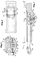
- FIG. 1 to 3 show a telescopic tension link or lower link arrangement 10 which contains a hollow first link 12 which can be fastened to a tractor (not shown).
- the rear area of the connecting member 12, which points away from the tractor, is essentially U-shaped and contains an upper wall 14 and a lower wall 16, which is best seen in FIG. 3.
- a plate 18 is welded to the lower and upper walls 14, 16 such that it includes a channel 20.
- a forged pocket 22 is molded into the vertically oriented base wall of the U-shaped first connecting member 12, which is located between the lower and upper walls 16, 14. The pocket 22 opens into the channel 20 and lies in the region of its front end, which points in the direction of the tractor.
- Two tap holes 24 and 25 extend perpendicular through the walls 14 and 16 and are directed towards the rear end of the pocket 22.
- Two further bores 26 and 27 extend vertically through the walls 14 and 16 and are directed towards the central region of the pocket 22.
- a spring bore 28 extends horizontally through one side of the link 12 into the pocket 22.
- a substantially rectangular locking plate 30 is secured within the pocket 22.
- Two pivots 32 and 33 are press-fitted into corresponding bores on the upper and lower end faces of the locking plate 30 and near their rear end.
- the pivot pins 32 and 33 are rotatably received by the pin holes 24 and 25.
- Two support bolts 34 and 35 are press-fitted into corresponding bores in the vicinity of the central region of the upper and lower end faces of the locking plate 30.
- the support bolts 34 and 35 are received by the bores 26 and 27.
- the diameters of the bores 26 and 27 are substantially larger than the diameters of the support bolts 34 and 35, and the free play between them allows the locking plate 30 to be pivoted between a locking position and an unlocking position.
- An actuator or button 36 is connected to the end of the support bolt 34 outside the upper wall 14 so that an operator can pivot the locking plate 30 about the pivots 32 and 33 as desired.
- a blind bore 38 extends horizontally partially into a side surface of the locking plate 30. It should be emphasized that the lower support pin 35 and the bore 27 can be omitted since the pivot pins 32 and 33 and the bores 24 and 25 are sufficient to maintain the correct alignment of the locking plate 30 in the pocket 22.
- a second connecting member 40 has a rear end 42 to which an attachment (not shown) can be coupled and a front end 44.
- the front end 44 can be inserted into the channel 20.
- the recess 46 essentially represents a transverse notch. It contains a surface 48 which is inclined with respect to a longitudinal axis of the second connecting member 40 relative to the surface thereof.
- the surface 48 is oriented to the side and slightly forward and adjoins a shoulder surface 50 which extends substantially transversely to the connecting member 40 and is oriented to the rear.
- a coil spring 52 is inserted into the spring bore 28 and is held in its orientation by a screw 54, which is screwed into an outer threaded section of the spring bore 28.
- the inner end of the coil spring 52 is received through the blind hole 38 of the locking plate 30.
- the coil spring 52 is biased to pivot the locking plate 30 about the axis of the pivot pins 32 and 33 and to urge the front end of the locking plate 30 out of the pocket 22 and into the channel 20.
- FIG. 5 shows a preferred embodiment of the invention, which is similar to the embodiment shown in FIGS. 1 to 4, but differs from it in that the pin holes 24 and 25 and the pivot pins 32 and 33 are omitted.
- the rear end of the locking plate 30 is pivotally held in the pocket 22 only between the first link 12 and the surface of the second link 40.
- the second link 40 becomes the first link 12 pushed out, so the relative position between the coil spring 52 and the support bolts 34, 35 and bores 26, 27, that the rear end of the locking plate 30 is pressed into the position shown in Fig. 1.
- the front end of the link 40 engages on the side surface of the locking plate 30 projecting into the channel 20 and presses the locking plate 30 against the force of the coil spring 52 the pocket 22.
- the coil spring 52 automatically pivots the locking plate 30 into a locking position in which the free, front end of the locking plate 30 in the recess 46 protrudes. In this locking position, the front end face of the locking plate 30 engages with the shoulder surface 50 of the recess 46 and prevents the second connecting member 40 from being inadvertently pulled out of the channel 20.
- the locking plate 30 can be pivoted manually out of the recess 46 by the button 36 on the side is displaced in the direction of the outer surface of the base wall of the U-shaped first connecting member 12, whereupon the second connecting member 40 can be pulled out of the channel 20 or extended with respect to the channel 20.
- the locking plate 30 is only subjected to compressive forces and not to shear or stretching forces.
- the locking plate 30 is not at risk of seizing, as is the case with other designs. If the tap holes 24 and 25 and the pivot pins 32 and 33 are used, then only the need Tap holes 24 and 25 to be drilled precisely in the first link 12. Other tolerances are not critical.
Landscapes
- Engineering & Computer Science (AREA)
- Mechanical Engineering (AREA)
- Life Sciences & Earth Sciences (AREA)
- Transportation (AREA)
- Zoology (AREA)
- Soil Sciences (AREA)
- Environmental Sciences (AREA)
- Agricultural Machines (AREA)
- Lifting Devices For Agricultural Implements (AREA)
- Lock And Its Accessories (AREA)
- Ladders (AREA)
Abstract
Description
- Die Erfindung betrifft eine teleskopierbare Verbindungsgliedanordnung mit einem ersten, einen Kanal enthaltenden Verbindungsglied, mit einem zweiten, im Kanal verschiebbar anordenbaren Verbindungsglied und mit Verriegelungsmitteln zum lösbaren Halten des zweiten Verbindungsgliedes in einer bezüglich des ersten Verbindungsgliedes eingezogenen Lage. Das zweite Verbindungsglied enthält eine quer zu seiner Bewegungsrichtung ausgerichtete Schulterfläche, die mit einem federvorgespannten Verriegelungselement zusammenwirkt, um ein Herausziehen des zweiten Verbindungsgliedes aus dem Kanal zu verhindern.
- Teleskopierbare Verbindungsgliedanordnungen finden beispielsweise bei Unterlenkern von Ackerschleppern Anwendung, die dem Ankoppeln von Anbaugeräten dienen. Der Unterlenker wird dabei in einem Kanal eines an dem Schlepper angelenkten Koppelgliedes geführt und durch einen zylindrischen Verriegelungsbolzen in seiner Lage festgehalten. Der Verriegelungsbolzen wird durch eine Feder in entsprechenden Bohrungen der Verbindungsglieder gehalten. Eine derartige Anordnung muß genau gefertigt sein, um ordnungsgemäß zu funktionieren. Der Verriegelungsbolzen ist ferner Scher- und Dehnkräften ausgesetzt und kann sich in den Bohrungen festfressen.
- Eine andere bei Ackerschleppern bekannte teleskopierbare Zuggliedanordnung enthält ein Teil, das durch Schwerkraft in einen Schlitz am Zuggliedende hineinfällt. Auch diese Anordnung erfordert für eine problemlose Anwendung eine genaue Fertigung, was insbesondere dann schwierig ist, wenn die Teile geschmiedet werden.
- Die US-A-3,643,976 beschreibt eine Verriegelung für eine Zugarmverlängerung der eingangs genannten Art, bei dem die Zugarmverlängerung in einem hohlen Zugglied teleskopartig geführt ist. Die Zugarmverlängerung ist an ihrem hinteren, in das Zugglied eingeführten Ende hakenförmig ausgebildet und weist hier eine zu seinem vorderen Ende ausgerichtete Fläche auf. Das Zugglied enthält eine Öffnung, über der ein Gehäuse angeordnet ist. Das Gehäuse nimmt einen Schaft auf, welcher an seinem einen Ende eine Verriegelungshandhabe und an seinem anderen Ende ein Verriegelungswiderlager trägt. An dem Verriegelungswiderlager greift eine Feder an, die es durch die Öffnung in dem Zugglied drückt, so daß es bei eingeschobener Zugarmverlängerung hinter dessen Fläche greift und die Zugarmverlängerung in dem Zugglied arretiert. Auch diese Anordnung erfordert einen hohen Fertigungsaufwand. Es ist daher eine teleskopierbare Zuggliedanordnung wünschenswert, die sich einfach herstellen läßt.
- Die der Erfindung zugrunde liegende Aufgabe wird darin gesehen, eine teleskopierbare und verriegelbare Verbindungsgliedanordnung anzugeben, die lediglich einen geringen Fertigungsaufwand erfordert. Der Verriegelungsmechanismus soll keinen Scher- oder Dehn- und Zugkräften ausgesetzt sein. Probleme des Festsetzens oder Fressens sollen vermieden werden. Sich entsprechende rechte und linke Verbindungsgliedteile sollen identisch ausbildbar sein, so daß sich beispielsweise identische Schmiedestücke verwenden lassen.
- Die Aufgabe wird erfindungsgemäß durch die Lehre des Patentanspruchs 1 gelöst. Weitere vorteilhafte Ausgestaltungen und Weiterbildungen der Erfindung gehen aus den Unteransprüchen hervor.
- Die erfindungsgemäße teleskopierbare und verriegelbare Verbindungsgliedanordnung enthält ein hohles, beispielsweise an einem Schlepper montierbares erstes Verbindungsglied (Unterlenker) sowie ein zweites Verbindungsglied, an das Anbaugeräte montierbar sind, und das durch einen Kanal in dem ersten Verbindungsglied gleitend aufgenommen wird. In dem ersten Verbindungsglied ist eine zum Kanal offene Tasche eingeformt. In der Tasche ist eine Platte schwenkbar angeordnet, die durch eine Feder aus einer Entriegelungsstellung, bei der die Platte vollständig von der Tasche aufgenommen wird, in eine Verriegelungsstellung, bei der wenigstens ein Teil der Platte in den Kanal hineinragt, gedrückt wird. In das zweite Verbindungsglied ist eine Aussparung eingelassen. Eine Seite der Aussparung bildet eine Schulter, die mit der Platte in Eingriff bringbar ist, wodurch sich das zweite Verbindungsglied lösbar in einer eingezogenen Position festhalten läßt. Mit einem Betätigungsknopf läßt sich die Platte gegen die Kraft der Feder aus ihrer Verriegelungsstellung in die Tasche verschwenken, so daß das zweite Verbindungsglied frei ist und aus dem ersten Verbindungsglied herausgezogen werden kann.
- Die erfindungsgemäße Anordnung läßt sich mit geringem Aufwand fertigen, ohne daß es auf die Einhaltung von Tolleranzen besonders ankäme. Sie besteht aus wenigen, unkomplizierten Einzelteilen. Bei der Verriegelung liegt eine Stirnfläche der Platte an der Schulter des zweiten Verbindungsgliedes an, so daß kein Teil der Verriegelung Scher- oder Zug- und Dehnkräften ausgesetzt ist. Ein Festklemmen oder Festfressen kann nicht auftreten. Rechte und linke Ausbildungen der Erfindung können aus identischen Teilen gebildet werden.
- Anhand der Zeichnung, die Ausführungsbeispiele der Erfindung zeigt, werden nachfolgend die Erfindung sowie weitere Vorteile und vorteilhafte Weiterbildungen und Ausgestaltungen der Erfindung näher beschrieben und erläutert.
- Es zeigt:
- Fig. 1
- die Teilschnittansicht einer erfindungsgemäßen teleskopierbaren Zuggliedanordnung,
- Fig. 2
- eine Ansicht in Richtung der Pfeile 2-2 der Fig. 1, wobei zur Verdeutlichung ein Ausschnitt herausgebrochen ist,
- Fig. 3
- eine Ansicht entlang der Linie 3-3 der Fig. 1,
- Fig. 4
- eine perspektivische Darstellung eines Unterlenkers mit einem erfindungsgemäßen Kupplungsbereich und
- Fig. 5
- eine ähnliche Ansicht wie Fig. 2, die jedoch eine alternative Ausgestaltung der Erfindung betrifft.
- Aus den Figuren 1 bis 3 geht eine teleskopierbare Zugglied- oder Unterlenkeranordnung 10 hervor, welche ein hohles erstes, an einem nicht dargestellten Schlepper befestigbares Verbindungsglied 12 enthält. Der hintere, vom Schlepper weg weisende Bereich des Verbindungsgliedes 12 ist im wesentlichen U-förmig ausgebildet und enthält eine obere Wandung 14 und eine untere Wandung 16, was am besten aus Fig. 3 hervorgeht. Eine Platte 18 ist mit der unteren und oberen Wandung 14, 16 derart verschweißt, daß sie einen Kanal 20 einschließt. In die zwischen der unteren und oberen Wandung 16, 14 liegende vertikal ausgerichtete Basiswandung des U-förmigen ersten Verbindungsglieds 12 ist eine geschmiedete Tasche 22 eingeformt. Die Tasche 22 öffnet sich in den Kanal 20 und liegt im Bereich dessen vorderen, in Richtung Schlepper weisenden Endes. Zwei Zapflöcher 24 und 25 erstrecken sich senkrecht durch die Wandungen 14 und 16 und sind auf das hinteren Ende der Tasche 22 gerichtet. Zwei weitere Bohrungen 26 und 27 erstrecken sich vertikal durch die Wandungen 14 und 16 und sind auf den mittleren Bereich der Tasche 22 gerichtet. Eine Federbohrung 28 erstreckt sich horizontal durch eine Seite des Verbindungsglieds 12 in die Tasche 22 hinein.
- Eine im wesentlichen rechteckige Verriegelungsplatte 30 ist innerhalb der Tasche 22 befestigt. Zwei Drehzapfen 32 und 33 sind mittels Preßsitz in entsprechende Bohrungen auf der oberen und unteren Stirnfläche der Verriegelungsplatte 30 und in der Nähe ihres hinteren Endes eingesetzt. Die Drehzapfen 32 und 33 werden drehbar von den Zapflöchern 24 und 25 aufgenommen. Zwei Stützbolzen 34 und 35 sind mittels Preßsitz in entsprechende Bohrungen in der Nähe des mittleren Bereichs der oberen und unteren Stirnfläche der Verriegelungsplatte 30 in diese eingesetzt. Die Stützbolzen 34 und 35 werden von den Bohrungen 26 und 27 aufgenommen. Die Durchmesser der Bohrungen 26 und 27 sind wesentlich größer als die Durchmesser der Stützbolzen 34 und 35, und das freie Spiel zwischen ihnen erlaubt es, daß sich die Verriegelungsplatte 30 zwischen einer Verriegelungsposition und einer Entriegelungsposition verschwenken läßt. Ein Betätigungselement oder Knopf 36 ist außerhalb der oberen Wandung 14 mit dem Ende des Stützbolzens 34 verbunden, so daß eine Bedienungsperson die Verriegelungsplatte 30 wunschgemäß um die Drehzapfen 32 und 33 verschwenken kann. Eine Sackbohrung 38 erstreckt sich horizontal teilweise in eine Seitenfläche der Verriegelungsplatte 30 hinein. Es sei hervorgehoben, daß der untere Stützbolzen 35 und die Bohrung 27 entfallen können, da die Drehzapfen 32 und 33 und die Bohrungen 24 und 25 ausreichen, um eine korrekte Ausrichtung der Verriegelungsplatte 30 in der Tasche 22 aufrechtzuerhalten.
- Wie am besten aus Fig. 4 ersichtlich, weist ein zweites Verbindungsglied 40 ein hinteres Ende 42, an das ein nicht dargestelltes Anbaugerät ankuppelbar ist, und ein vorderes Ende 44 auf. Das vordere Ende 44 ist in den Kanal 20 einschiebbar. Auf einer Seite des zweiten Verbindungsglieds 40, nahe, jedoch beabstandet zu seinem vorderen Ende 44 ist eine Aussparung 46 eingelassen. Die Aussparung 46 stellt im wesentlichen eine quer verlaufende Kerbe dar. Sie enthält eine Oberfläche 48, die in bezug auf eine Längsachse des zweiten Verbindungsgliedes 40 gegenüber dessen Oberfläche geneigt verläuft. Die Oberfläche 48 ist zur Seite und leicht nach vorn ausgerichtet und grenzt an eine Schulterfläche 50 an, die im wesentlichen quer zum Verbindungsglied 40 verläuft und nach hinten ausgerichtet ist.
- Eine Schraubenfeder 52 ist in die Federbohrung 28 eingesetzt und wird durch eine Schraube 54, welche in einen äußeren Gewindeabschnitt der Federbohrung 28 eingeschraubt ist, in ihrer Ausrichtung gehalten. Das innere Ende der Schraubenfeder 52 wird durch die Sackbohrung 38 der Verriegelungsplatte 30 aufgenommen. Die Schraubenfeder 52 ist vorgespannt, um die Verriegelungsplatte 30 um die Achse der Drehzapfen 32 und 33 zu verschwenken und das vordere Ende der Verriegelungsplatte 30 aus der Tasche 22 heraus und in den Kanal 20 hinein zu drängen.
- Fig. 5 zeigt eine bevorzugte Ausgestaltung der Erfindung, die Ähnlichkeiten mit der in den Fig. 1 bis 4 dargestellten Ausgestaltung aufweist, sich jedoch von dieser dadurch unterscheidet, daß die Zapflöcher 24 und 25 und die Drehzapfen 32 und 33 entfallen. In diesem Fall wird das hintere Ende der Verriegelungsplatte 30 schwenkbar in der Tasche 22 lediglich zwischen dem ersten Verbindungsglied 12 und der Oberfläche des zweiten Verbindungsgliedes 40 festgehalten. Wird ferner das zweite Verbindungsglied 40 aus dem ersten Verbindungsglied 12 herausgeschoben, so bedingt die relative Lage zwischen der Schraubenfeder 52 und den Stützbolzen 34, 35 und Bohrungen 26, 27, daß das hintere Ende der Verriegelungsplatte 30 in die in Fig. 1 gezeigte Lage gedrückt wird.
- Wird das zweite Verbindungsglied 40 bezüglich Fig. 1 nach rechts in den Kanal 20 hinein bewegt, so greift das vordere Ende des Verbindungsgliedes 40 an der in den Kanal 20 ragenden Seitenfläche der Verriegelungsplatte 30 an und drückt die Verriegelungsplatte 30 gegen die Kraft der Schraubenfeder 52 in die Tasche 22. Erreicht die Aussparung 46 eine Lage, die benachbart zur Tasche 22 liegt, wie es in Fig. 1 dargestellt ist, schwenkt die Schraubenfeder 52 die Verriegelungsplatte 30 automatisch in eine Sperrposition, in der das freie, vordere Ende der Verriegelungsplatte 30 in die Aussparung 46 hineinragt. In dieser Sperrposition tritt die vordere Stirnfläche der Verriegelungsplatte 30 mit der Schulterfläche 50 der Aussparung 46 in Eingriff und verhindert ein unbeabsichtigtes Herausziehen des zweiten Verbindungsgliedes 40 aus dem Kanal 20. Die Verriegelungsplatte 30 läßt sich manuell aus der Aussparung 46 verschwenken, indem der Knopf 36 seitlich in Richtung der Außenfläche der Basiswandung des Uförmigen ersten Verbindungsglieds 12 verschoben wird, woraufhin das zweite Verbindungsglied 40 aus dem Kanal 20 herausgezogen oder bezüglich des Kanals 20 verlängert werden kann.
- Mit dieser Konstruktion können gleiche Teile auf der linken und rechten Seite der nicht dargestellten Gerätekupplung des Schleppers verwendet werden. Die Verriegelungsplatte 30 ist lediglich Druckkräften und nicht Scher- oder Dehnkräften ausgesetzt. Die Verriegelungsplatte 30 ist nicht der Gefahr des Festfressens ausgesetzt, wie es bei anderen Konstruktionen der Fall ist. Werden die Zapflöcher 24 und 25 und die Drehzapfen 32 und 33 verwendet, dann brauchen lediglich die Zapflöcher 24 und 25 genau in das erste Verbindungsglied 12 gebohrt zu werden. Weitere Tolleranzen sind unkritisch.
- Auch wenn die Erfindung lediglich anhand einiger Ausführungsbeispiele beschrieben wurde, erschließen sich für den Fachmann im Lichte der vorstehenden Beschreibung viele verschiedenartige Alternativen, Modifikationen und Varianten, die unter die vorliegende Erfindung fallen. So ist es beispielsweise möglich, in dem zweiten Verbindungsglied 40 weitere in Längsrichtung hintereinander liegende Aussparungen vorzusehen, so daß das zweite Verbindungsglied 40 sich in mehreren Positionen verriegeln läßt, wodurch sich unterschiedliche Anbauabstände relativ zum Schlepper ergeben. Die Erfindung läßt sich auch bei Unterlenkern anwenden, die vorn an einem Schlepper montierbar sind. In diesem Fall sind die obigen Angaben bezüglich vorn und hinten zu vertauschen.
Applications Claiming Priority (2)
| Application Number | Priority Date | Filing Date | Title |
|---|---|---|---|
| US08/009,610 US5327978A (en) | 1993-01-27 | 1993-01-27 | Extendable latchable draft link |
| US9610 | 1993-01-27 |
Publications (2)
| Publication Number | Publication Date |
|---|---|
| EP0608750A1 true EP0608750A1 (de) | 1994-08-03 |
| EP0608750B1 EP0608750B1 (de) | 1996-12-18 |
Family
ID=21738706
Family Applications (1)
| Application Number | Title | Priority Date | Filing Date |
|---|---|---|---|
| EP94100636A Expired - Lifetime EP0608750B1 (de) | 1993-01-27 | 1994-01-18 | Teleskopierbare und verriegelbare Verbindungsgliedanordnung |
Country Status (7)
| Country | Link |
|---|---|
| US (1) | US5327978A (de) |
| EP (1) | EP0608750B1 (de) |
| AR (1) | AR248239A1 (de) |
| BR (1) | BR9400069A (de) |
| CA (1) | CA2114062C (de) |
| DE (1) | DE59401286D1 (de) |
| MX (1) | MX9307797A (de) |
Cited By (3)
| Publication number | Priority date | Publication date | Assignee | Title |
|---|---|---|---|---|
| DE19849070C1 (de) * | 1998-10-24 | 1999-10-28 | Walterscheid Gmbh Gkn | Unterlenkerbaueinheit für eine Geräteanbaueinrichtung |
| DE19849061C1 (de) * | 1998-10-24 | 1999-10-28 | Walterscheid Gmbh Gkn | Unterlenkerbaueinheit für eine Anbaueinrichtung eines Traktors |
| DE102004008564A1 (de) * | 2004-02-19 | 2005-09-01 | Volkswagen Ag | Anhängerzugvorrichtung sowie Fahrzeug mit Anhängerzugvorrichtung |
Families Citing this family (10)
| Publication number | Priority date | Publication date | Assignee | Title |
|---|---|---|---|---|
| DE19605560C1 (de) * | 1996-02-15 | 1997-08-14 | Walterscheid Gmbh Gkn | Hubstange für die Dreipunktanbaueinrichtung eines Traktors |
| US7293791B1 (en) | 2002-07-26 | 2007-11-13 | Williams Jr Thomas M | Telescoping and swiveling hitch assembly |
| US7584984B1 (en) | 2005-05-16 | 2009-09-08 | Williams Innovations, Llc | Telescoping and swiveling hitch assembly |
| BRPI0502606B1 (pt) * | 2005-07-07 | 2012-05-15 | barra extensìvel com sistema de travamento simplificado. | |
| DE102006009673A1 (de) * | 2006-03-02 | 2007-09-06 | Deere & Company, Moline | Gehäuse eines Teleskoplenkers |
| US7975776B2 (en) * | 2007-04-23 | 2011-07-12 | Larry Chimento | Adjustable towing hitch |
| DE102008007299A1 (de) | 2008-02-02 | 2009-08-06 | Deere & Company, Moline | Unterlenkerzusammenbau für eine Anbaueinrichtung eines Traktors |
| US7784558B2 (en) * | 2008-04-30 | 2010-08-31 | Cnh America Llc | Three point hitch |
| GB201020863D0 (en) * | 2010-12-09 | 2011-01-26 | Agco Internat Ltd | Linkage rocker arm on an agricultural vehicle |
| GB2544462A (en) * | 2015-11-04 | 2017-05-24 | Kverneland Group Kerteminde As | Carrier arm assembly |
Citations (4)
| Publication number | Priority date | Publication date | Assignee | Title |
|---|---|---|---|---|
| US2828974A (en) * | 1955-08-25 | 1958-04-01 | John E Jameson | Automatic coupling devices for vehicles |
| DE1045701B (de) * | 1956-10-05 | 1958-12-04 | Int Harvester Co | Geraeteanbauvorrichtung fuer Ackerschlepper |
| GB1113741A (en) * | 1964-12-02 | 1968-05-15 | Kloeckner Humboldt Deutz Ag | Lower link of implement-hitching device serving to hitch agricultural implements to tractors |
| FR2061572A1 (de) * | 1969-07-25 | 1971-06-25 | Renault |
Family Cites Families (7)
| Publication number | Priority date | Publication date | Assignee | Title |
|---|---|---|---|---|
| US2340786A (en) * | 1941-10-20 | 1944-02-01 | Sidney B Winn | Extensible pintle hook trailer coupling |
| US2717163A (en) * | 1953-09-18 | 1955-09-06 | Paul H Martin | Connection facilitating vehicle draft means |
| US3226818A (en) * | 1964-09-22 | 1966-01-04 | Paul D Abbott | Method of making a ball and socket type hitch |
| GB1159135A (en) * | 1965-11-26 | 1969-07-23 | Kloeckner Humboldt Deutz Ag | A Link Bar for an Appliance-attachment Device for Motor Vehicles |
| GB1158640A (en) * | 1966-09-29 | 1969-07-16 | Robert Henry Francis Jeffes | Improvements in or relating to a Telescopic Drawbar |
| US3446518A (en) * | 1967-05-04 | 1969-05-27 | Barsyke Ltd | Selectively extensible telescoping hitch link |
| US3643976A (en) * | 1970-10-19 | 1972-02-22 | Allis Chalmers Mfg Co | Latch for draft arm extension |
-
1993
- 1993-01-27 US US08/009,610 patent/US5327978A/en not_active Expired - Lifetime
- 1993-12-09 MX MX9307797A patent/MX9307797A/es not_active IP Right Cessation
-
1994
- 1994-01-11 BR BR9400069A patent/BR9400069A/pt not_active IP Right Cessation
- 1994-01-14 AR AR94327199A patent/AR248239A1/es active
- 1994-01-18 EP EP94100636A patent/EP0608750B1/de not_active Expired - Lifetime
- 1994-01-18 DE DE59401286T patent/DE59401286D1/de not_active Expired - Lifetime
- 1994-01-24 CA CA002114062A patent/CA2114062C/en not_active Expired - Fee Related
Patent Citations (4)
| Publication number | Priority date | Publication date | Assignee | Title |
|---|---|---|---|---|
| US2828974A (en) * | 1955-08-25 | 1958-04-01 | John E Jameson | Automatic coupling devices for vehicles |
| DE1045701B (de) * | 1956-10-05 | 1958-12-04 | Int Harvester Co | Geraeteanbauvorrichtung fuer Ackerschlepper |
| GB1113741A (en) * | 1964-12-02 | 1968-05-15 | Kloeckner Humboldt Deutz Ag | Lower link of implement-hitching device serving to hitch agricultural implements to tractors |
| FR2061572A1 (de) * | 1969-07-25 | 1971-06-25 | Renault |
Cited By (9)
| Publication number | Priority date | Publication date | Assignee | Title |
|---|---|---|---|---|
| DE19849070C1 (de) * | 1998-10-24 | 1999-10-28 | Walterscheid Gmbh Gkn | Unterlenkerbaueinheit für eine Geräteanbaueinrichtung |
| DE19849061C1 (de) * | 1998-10-24 | 1999-10-28 | Walterscheid Gmbh Gkn | Unterlenkerbaueinheit für eine Anbaueinrichtung eines Traktors |
| EP0995349A1 (de) | 1998-10-24 | 2000-04-26 | GKN Walterscheid GmbH | Unterlenkbaueinheit für eine Anbauvorrichtung eines Traktors |
| GB2343831A (en) * | 1998-10-24 | 2000-05-24 | Walterscheid Gmbh Gkn | Lower steering arm assembly for an implement attaching device |
| GB2343831B (en) * | 1998-10-24 | 2001-01-03 | Walterscheid Gmbh Gkn | Lower steering arm assembly for an implement attaching device |
| US6227305B1 (en) | 1998-10-24 | 2001-05-08 | Gkn Walterscheid Gmbh | Lower steering arm assembly for an attaching device of a tractor |
| US6267023B1 (en) | 1998-10-24 | 2001-07-31 | Gkn Walterscheid Gmbh | Lower steering arm assembly for an implement attaching device |
| DE102004008564A1 (de) * | 2004-02-19 | 2005-09-01 | Volkswagen Ag | Anhängerzugvorrichtung sowie Fahrzeug mit Anhängerzugvorrichtung |
| DE102004008564B4 (de) * | 2004-02-19 | 2014-06-26 | Volkswagen Ag | Anhängerzugvorrichtung sowie Fahrzeug mit Anhängerzugvorrichtung |
Also Published As
| Publication number | Publication date |
|---|---|
| EP0608750B1 (de) | 1996-12-18 |
| BR9400069A (pt) | 1994-08-16 |
| CA2114062A1 (en) | 1994-07-28 |
| CA2114062C (en) | 1997-12-30 |
| US5327978A (en) | 1994-07-12 |
| MX9307797A (es) | 1994-07-29 |
| AR248239A1 (es) | 1995-07-12 |
| DE59401286D1 (de) | 1997-01-30 |
Similar Documents
| Publication | Publication Date | Title |
|---|---|---|
| AT404779B (de) | Seitenstrebe für den unterlenker eines traktors | |
| EP0608750B1 (de) | Teleskopierbare und verriegelbare Verbindungsgliedanordnung | |
| EP1146185A2 (de) | Fahrzeugschloss, insbesondere für eine Heckklappentür | |
| EP2047206A1 (de) | Scharnieranordnung für eine waffe, visieranordnung und waffe | |
| WO2009100548A1 (de) | Steg zum verbinden der beiden zylinderhälften eines längenvariablen doppelschliesszylinders | |
| EP1522635B1 (de) | Schnellwechselkupplung zur Befestigung der Arbeitswerkzeuge an einem Baggerausleger | |
| DE10344555B4 (de) | Vorrichtung zum Führen und/oder Fixieren eines Zugpendels für ein Fahrzeug | |
| EP0568921A1 (de) | Kupplungseinrichtung | |
| EP0529427A1 (de) | Anhängevorrichtung mit Zugpendel | |
| DE69819380T2 (de) | Federscharnier | |
| DE2749914A1 (de) | Halterung fuer ein bein an einem massiven koerper | |
| DE602005003280T2 (de) | Hebelsteckverbinder | |
| DE10204766A1 (de) | Gelenk für eine Fahrzeugtür | |
| DE3447178C2 (de) | ||
| EP1066440A1 (de) | Montageplatte für möbelscharniere | |
| DE29808914U1 (de) | Mechanische Verriegelungsanordnung | |
| WO1999000288A1 (de) | Sattelkupplung | |
| DE60022559T2 (de) | Türverriegelungsvorrichtung | |
| EP1210274B1 (de) | Hakenelement | |
| DE102014100272B4 (de) | Gehäuseanordnung | |
| DE102020100411B3 (de) | Bandlappen eines Bandes zur scharniergelenkigen Verbindung eines Flügelprofils mit einem Rahmenprofil und ein solches Band | |
| DE4339042C1 (de) | Vorrichtung zur Befestigung eines Bauteils an einem Verbindungsstift | |
| DE69015976T2 (de) | Baugerüst. | |
| EP0943487A2 (de) | Vorrichtung zum lösbaren Verbinden mit einem Bügel | |
| DE10050143A1 (de) | Bolzensicherung |
Legal Events
| Date | Code | Title | Description |
|---|---|---|---|
| PUAI | Public reference made under article 153(3) epc to a published international application that has entered the european phase |
Free format text: ORIGINAL CODE: 0009012 |
|
| AK | Designated contracting states |
Kind code of ref document: A1 Designated state(s): DE FR GB IT |
|
| 17P | Request for examination filed |
Effective date: 19940728 |
|
| 17Q | First examination report despatched |
Effective date: 19951120 |
|
| GRAG | Despatch of communication of intention to grant |
Free format text: ORIGINAL CODE: EPIDOS AGRA |
|
| GRAH | Despatch of communication of intention to grant a patent |
Free format text: ORIGINAL CODE: EPIDOS IGRA |
|
| GRAH | Despatch of communication of intention to grant a patent |
Free format text: ORIGINAL CODE: EPIDOS IGRA |
|
| GRAA | (expected) grant |
Free format text: ORIGINAL CODE: 0009210 |
|
| AK | Designated contracting states |
Kind code of ref document: B1 Designated state(s): DE FR GB IT |
|
| ITF | It: translation for a ep patent filed | ||
| REF | Corresponds to: |
Ref document number: 59401286 Country of ref document: DE Date of ref document: 19970130 |
|
| ET | Fr: translation filed | ||
| GBT | Gb: translation of ep patent filed (gb section 77(6)(a)/1977) |
Effective date: 19970207 |
|
| PLBE | No opposition filed within time limit |
Free format text: ORIGINAL CODE: 0009261 |
|
| STAA | Information on the status of an ep patent application or granted ep patent |
Free format text: STATUS: NO OPPOSITION FILED WITHIN TIME LIMIT |
|
| 26N | No opposition filed | ||
| PGFP | Annual fee paid to national office [announced via postgrant information from national office to epo] |
Ref country code: GB Payment date: 20001219 Year of fee payment: 8 |
|
| PGFP | Annual fee paid to national office [announced via postgrant information from national office to epo] |
Ref country code: FR Payment date: 20010119 Year of fee payment: 8 |
|
| REG | Reference to a national code |
Ref country code: GB Ref legal event code: IF02 |
|
| PG25 | Lapsed in a contracting state [announced via postgrant information from national office to epo] |
Ref country code: GB Free format text: LAPSE BECAUSE OF NON-PAYMENT OF DUE FEES Effective date: 20020118 |
|
| GBPC | Gb: european patent ceased through non-payment of renewal fee |
Effective date: 20020118 |
|
| PG25 | Lapsed in a contracting state [announced via postgrant information from national office to epo] |
Ref country code: FR Free format text: LAPSE BECAUSE OF NON-PAYMENT OF DUE FEES Effective date: 20020930 |
|
| REG | Reference to a national code |
Ref country code: FR Ref legal event code: ST |
|
| PGFP | Annual fee paid to national office [announced via postgrant information from national office to epo] |
Ref country code: IT Payment date: 20090129 Year of fee payment: 16 |
|
| PG25 | Lapsed in a contracting state [announced via postgrant information from national office to epo] |
Ref country code: IT Free format text: LAPSE BECAUSE OF NON-PAYMENT OF DUE FEES Effective date: 20100118 |
|
| PGFP | Annual fee paid to national office [announced via postgrant information from national office to epo] |
Ref country code: DE Payment date: 20121219 Year of fee payment: 20 |
|
| REG | Reference to a national code |
Ref country code: DE Ref legal event code: R071 Ref document number: 59401286 Country of ref document: DE |
|
| PG25 | Lapsed in a contracting state [announced via postgrant information from national office to epo] |
Ref country code: DE Free format text: LAPSE BECAUSE OF EXPIRATION OF PROTECTION Effective date: 20140121 |