EP0608810A2 - Dispositif de contrôle de la position d'impression - Google Patents
Dispositif de contrôle de la position d'impression Download PDFInfo
- Publication number
- EP0608810A2 EP0608810A2 EP94100984A EP94100984A EP0608810A2 EP 0608810 A2 EP0608810 A2 EP 0608810A2 EP 94100984 A EP94100984 A EP 94100984A EP 94100984 A EP94100984 A EP 94100984A EP 0608810 A2 EP0608810 A2 EP 0608810A2
- Authority
- EP
- European Patent Office
- Prior art keywords
- printing position
- linear encoder
- phases
- information
- controlling
- Prior art date
- Legal status (The legal status is an assumption and is not a legal conclusion. Google has not performed a legal analysis and makes no representation as to the accuracy of the status listed.)
- Granted
Links
Images
Classifications
-
- B—PERFORMING OPERATIONS; TRANSPORTING
- B41—PRINTING; LINING MACHINES; TYPEWRITERS; STAMPS
- B41J—TYPEWRITERS; SELECTIVE PRINTING MECHANISMS, i.e. MECHANISMS PRINTING OTHERWISE THAN FROM A FORME; CORRECTION OF TYPOGRAPHICAL ERRORS
- B41J19/00—Character- or line-spacing mechanisms
- B41J19/18—Character-spacing or back-spacing mechanisms; Carriage return or release devices therefor
- B41J19/20—Positive-feed character-spacing mechanisms
- B41J19/202—Drive control means for carriage movement
- B41J19/205—Position or speed detectors therefor
Definitions
- the present invention relates to a device for controlling a printing position which device is used for a printer device, and more particularly to the device for controlling a printing position which device provides a control circuit so that the control circuit may control one linear encoder to store two pieces of information about an absolute position at a magnetization period of a minimum resolution and an integer-fold magnetization period of a minimum resolution for controlling the printing position in the printer.
- the present device may be used for an ink-jet printer, a thermal printer, a facsimile, or a wire-dot printer.
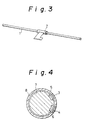
- Fig. 3 is a view showing a conventional linear encoder for storing two pieces of information on two phases.
- Fig. 4 is a schematic section showing the linear encoder shown in Fig. 3.
- 1 denotes a linear encoder (magnetic memory type).
- 2 denotes a linear encoder element (MR head unit).
- 3 denotes a first sensing head for sensing a printing position.
- 4 denotes a second sensing head for sensing a carriage position.
- 5 denotes a first magnetizing part for storing information about a printing position.
- 6 denotes a second magnetizing part for storing information about a carriage position.
- 7 denotes a magnetic memory part.
- 8 denotes a slide metal.
- the linear encoder stores the information about a printing position at the first magnetizing part 5 and the information about a carriage position at the second magnetizing part 6, the first magnetizing part 5 being different in pitch from the second magnetizing part 6, that is, two kinds of informations being stored in two storage parts located on the longitudinal axis of the linear encoder.
- the two kinds of position information are sensed by the first and the second sensing elements provided in the slide metal 8 of the MR head part 2, respectively.
- the conventional linear encoder is required to keep a considerable degree of accuracy about sensing positions around the slide metal so that the first sensing head may match in position to the first magnetizing part and the second sensing head may match in position to the second magnetizing part for obtaining the position information.
- the first and the second magnetizing parts that is, for sensing the stored informations on two phases
- the first and the second two heads are required, which results in making the overall device more costly.
- the object of the invention can be achieved by a device for controlling a printing position comprising a linear encoder for storing two pieces of information on two phases about a printing position in one storage part located on a longitudinal axis of the linear encoder, reading means movably located along the storage part of the linear encoder and for reading the pieces of information on two phases stored in the storage part of the linear encoder, and control circuits for controlling the printing position based on the informations on two phases read by the reading means.
- the linear encoder stores the two pieces of information on two phases about a printing position in one storage part located on the longitudinal axis. Hence, the informations on two phases are allowed to be read by just one reading means, which makes it possible to manufacture a device for controlling a printing position at low cost.
- the linear encoder stores informations on two phases about a printing position in one storage part located on a longitudinal axis of the linear encoder. Hence, the informations on two phases are allowed to be read by one reading means, so that the device for controlling a printing position may be manufactured at low cost.
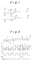
- Fig. 1 is a diagram showing a control circuit according to an embodiment.
- Fig. 2 is a view for explaining reading of information from a linear encoder for storing informations on two phases.
- Fig. 3 is a view for explaining a conventional linear encoder for storing information on two phases.
- Fig. 4 is a schematic section showing the linear encoder shown in Fig. 3.
- Fig. 1 is a diagram showing a control circuit for controlling two pieces of information on two phases.
- Fig. 2 is a view for explaining reading of positional information from the linear encoder having the informations about a printing position and a carriage position stored (magnetized) thereon.
- 10 denotes one storage part located on a longitudinal axis of a linear encoder.
- 11 denotes a magnetizing (storing) part for storing information about a printing position at a magnetizing period of a minimum resolution.
- 12 denotes an MR head served as reading means.
- 13 denotes a magnetizing (storing) part for storing information about a carriage position stored at an integer-fold magnetizing period of a minimum resolution.
- 26 denotes a waveform of a signal read by the MR head 2 served as reading means.
- 17 denotes a waveform of a signal corresponding to the magnetizing part 11.
- 18 denotes a waveform of a signal at the magnetizing part 14.
- 15 denotes a threshold value about the magnetizing part 14.
- 16 denotes a threshold value about the magnetizing part 11.
- Fig. 2 one of the informations on two phases is stored in the magnetizing part 11 and the other is stored in the magnetizing part 14 at an integer-fold interval from the normal magnetizing part 11.
- the force of magnetization provided in the magnetizing part 14 is stronger than that provided in the magnetizing part 11.
- 24 and 25 denote comparators having respective threshold values.
- the signal 26 generated as the MR head is moved from the terminal 19 to the comparators 24 and 25 is inputted to the comparators 24 and 25 respectively.
- the comparator 24 holds a threshold value 16 set through the terminal 20 and the comparator 25 holds a threshold value 15 set through the terminal 21.
- the signal 26 is inputted to both of the comparators 24 and 25, if the signal 26 is higher than each of their threshold values, that is, if the signal 26 is higher than the threshold value 16, the signal 17 is outputted at the output terminal 22 of the comparator 24 and if the signal 26 is higher than the threshold value 15, the signal 16 is outputted at the output terminal 23 of the comparator 25.
- the information about a printing position is obtained on the magnetizing part 11 and the information about a carriage position is obtained on the magnetizing part 14.
- the control of the printing position and the carriage position based on the information magnetized in one storing part of one linear encoder along one travel of one MR head are allowed to be realized with a simple arrangement and at low cost.
- the magnetizations on two phases are done once so as to keep a phase difference between the two phases highly accurate.
Landscapes
- Character Spaces And Line Spaces In Printers (AREA)
- Accessory Devices And Overall Control Thereof (AREA)
Applications Claiming Priority (2)
| Application Number | Priority Date | Filing Date | Title |
|---|---|---|---|
| JP11742/93 | 1993-01-27 | ||
| JP5011742A JPH06219007A (ja) | 1993-01-27 | 1993-01-27 | 印字位置制御装置 |
Publications (3)
| Publication Number | Publication Date |
|---|---|
| EP0608810A2 true EP0608810A2 (fr) | 1994-08-03 |
| EP0608810A3 EP0608810A3 (en) | 1995-08-23 |
| EP0608810B1 EP0608810B1 (fr) | 1999-04-07 |
Family
ID=11786482
Family Applications (1)
| Application Number | Title | Priority Date | Filing Date |
|---|---|---|---|
| EP94100984A Expired - Lifetime EP0608810B1 (fr) | 1993-01-27 | 1994-01-24 | Dispositif de contrÔle de la position d'impression |
Country Status (4)
| Country | Link |
|---|---|
| US (1) | US5433542A (fr) |
| EP (1) | EP0608810B1 (fr) |
| JP (1) | JPH06219007A (fr) |
| DE (1) | DE69417595T2 (fr) |
Families Citing this family (2)
| Publication number | Priority date | Publication date | Assignee | Title |
|---|---|---|---|---|
| US6609781B2 (en) | 2000-12-13 | 2003-08-26 | Lexmark International, Inc. | Printer system with encoder filtering arrangement and method for high frequency error reduction |
| CN1331670C (zh) * | 2004-03-31 | 2007-08-15 | 明基电通股份有限公司 | 打印机及其喷墨方法 |
Family Cites Families (9)
| Publication number | Priority date | Publication date | Assignee | Title |
|---|---|---|---|---|
| GB1603682A (en) * | 1977-05-31 | 1981-11-25 | Nippon Electric Co | Position control system |
| US4180704A (en) * | 1978-06-28 | 1979-12-25 | International Business Machines Corporation | Detection circuit for a bi-directional, self-imaging grating detector |
| US4529325A (en) * | 1982-05-26 | 1985-07-16 | Oume Corporation | Technique for compensation for bandwidth limitations of microprocessor utilized for serial printer control |
| JPS60161160A (ja) * | 1984-01-31 | 1985-08-22 | Nec Home Electronics Ltd | ドツトラインプリンタ |
| JPH04229702A (ja) * | 1990-06-20 | 1992-08-19 | Canon Inc | 信号処理方法及び装置、並びにこれを用いた変位検出装置等のシステム |
| US5168274A (en) * | 1990-10-17 | 1992-12-01 | Olympus Optical Co., Ltd. | Position detector device |
| JP3313750B2 (ja) * | 1992-01-21 | 2002-08-12 | キヤノン株式会社 | 信号処理装置及びこれを用いた装置 |
| JPH068564A (ja) * | 1992-06-25 | 1994-01-18 | Canon Inc | 記録装置 |
| US5291133A (en) * | 1992-08-24 | 1994-03-01 | General Motors Corporation | Multi-bit encoder signal conditioning circuit having common mode disturbance compensation |
-
1993
- 1993-01-27 JP JP5011742A patent/JPH06219007A/ja active Pending
-
1994
- 1994-01-24 DE DE69417595T patent/DE69417595T2/de not_active Expired - Lifetime
- 1994-01-24 EP EP94100984A patent/EP0608810B1/fr not_active Expired - Lifetime
- 1994-01-25 US US08/186,785 patent/US5433542A/en not_active Expired - Lifetime
Also Published As
| Publication number | Publication date |
|---|---|
| EP0608810A3 (en) | 1995-08-23 |
| US5433542A (en) | 1995-07-18 |
| DE69417595T2 (de) | 1999-09-23 |
| DE69417595D1 (de) | 1999-05-12 |
| EP0608810B1 (fr) | 1999-04-07 |
| JPH06219007A (ja) | 1994-08-09 |
Similar Documents
| Publication | Publication Date | Title |
|---|---|---|
| US7591427B2 (en) | Method and system for a static magnetic read/write head | |
| US6630821B2 (en) | Magnetic detection device for detecting moving direction of a toothed magnetic movable body | |
| US5430373A (en) | Absolute encoder | |
| US5476324A (en) | Spline bearing | |
| EP0344958A1 (fr) | Circuit de commande de tête | |
| US4460867A (en) | Method and circuit for measuring of current | |
| JP3377539B2 (ja) | 磁気インク文字読取り用磁気抵抗ヘッド | |
| US5433542A (en) | Device for controlling printing position | |
| JPS6155711B2 (fr) | ||
| US6898865B2 (en) | Measuring system for recording absolute angular or position values | |
| US4167014A (en) | Circuitry for perfecting ink drop printing at varying carrier velocity | |
| US20010055231A1 (en) | Apparatus and method for detecting the temperature in a disk memory device | |
| US4757257A (en) | Magnetoresistive displacement sensor and signal processing circuit | |
| US4636884A (en) | Head positioning control system in magnetic disk device of index servo system | |
| JPS6191503A (ja) | 弁の変位検出装置 | |
| DE3417570A1 (de) | Steuervorrichtung fuer einen schreib/lesekopfantrieb | |
| CA1112330A (fr) | Transducteur de deplacement numerique et methode de mesure | |
| JP3923633B2 (ja) | 情報記録媒体 | |
| JP3177931B2 (ja) | 原点検出方法およびカメラ | |
| JP3233317B2 (ja) | 磁気式エンコーダ | |
| JPH04195811A (ja) | 磁気イメージセンサ | |
| JPH01302101A (ja) | 位置検出装置 | |
| JPH0529841B2 (fr) | ||
| JPH051773Y2 (fr) | ||
| US3434131A (en) | Pulse width sensitive magnetic head with associated binary identification circuit |
Legal Events
| Date | Code | Title | Description |
|---|---|---|---|
| PUAI | Public reference made under article 153(3) epc to a published international application that has entered the european phase |
Free format text: ORIGINAL CODE: 0009012 |
|
| AK | Designated contracting states |
Kind code of ref document: A2 Designated state(s): DE FR GB |
|
| RIN1 | Information on inventor provided before grant (corrected) |
Inventor name: SUMIDA, KOHICHI Inventor name: KOBAYASHI, KUNIHIRO Inventor name: MASUDA, KAZUYA |
|
| PUAL | Search report despatched |
Free format text: ORIGINAL CODE: 0009013 |
|
| AK | Designated contracting states |
Kind code of ref document: A3 Designated state(s): DE FR GB |
|
| 17P | Request for examination filed |
Effective date: 19951116 |
|
| 17Q | First examination report despatched |
Effective date: 19961127 |
|
| GRAG | Despatch of communication of intention to grant |
Free format text: ORIGINAL CODE: EPIDOS AGRA |
|
| GRAG | Despatch of communication of intention to grant |
Free format text: ORIGINAL CODE: EPIDOS AGRA |
|
| GRAH | Despatch of communication of intention to grant a patent |
Free format text: ORIGINAL CODE: EPIDOS IGRA |
|
| GRAH | Despatch of communication of intention to grant a patent |
Free format text: ORIGINAL CODE: EPIDOS IGRA |
|
| GRAA | (expected) grant |
Free format text: ORIGINAL CODE: 0009210 |
|
| AK | Designated contracting states |
Kind code of ref document: B1 Designated state(s): DE FR GB |
|
| REF | Corresponds to: |
Ref document number: 69417595 Country of ref document: DE Date of ref document: 19990512 |
|
| ET | Fr: translation filed | ||
| PLBE | No opposition filed within time limit |
Free format text: ORIGINAL CODE: 0009261 |
|
| STAA | Information on the status of an ep patent application or granted ep patent |
Free format text: STATUS: NO OPPOSITION FILED WITHIN TIME LIMIT |
|
| 26N | No opposition filed | ||
| REG | Reference to a national code |
Ref country code: GB Ref legal event code: IF02 |
|
| PGFP | Annual fee paid to national office [announced via postgrant information from national office to epo] |
Ref country code: FR Payment date: 20120202 Year of fee payment: 19 |
|
| PGFP | Annual fee paid to national office [announced via postgrant information from national office to epo] |
Ref country code: DE Payment date: 20120118 Year of fee payment: 19 |
|
| PGFP | Annual fee paid to national office [announced via postgrant information from national office to epo] |
Ref country code: GB Payment date: 20120118 Year of fee payment: 19 |
|
| GBPC | Gb: european patent ceased through non-payment of renewal fee |
Effective date: 20130124 |
|
| REG | Reference to a national code |
Ref country code: FR Ref legal event code: ST Effective date: 20130930 |
|
| PG25 | Lapsed in a contracting state [announced via postgrant information from national office to epo] |
Ref country code: DE Free format text: LAPSE BECAUSE OF NON-PAYMENT OF DUE FEES Effective date: 20130801 |
|
| REG | Reference to a national code |
Ref country code: DE Ref legal event code: R119 Ref document number: 69417595 Country of ref document: DE Effective date: 20130801 |
|
| PG25 | Lapsed in a contracting state [announced via postgrant information from national office to epo] |
Ref country code: GB Free format text: LAPSE BECAUSE OF NON-PAYMENT OF DUE FEES Effective date: 20130124 Ref country code: FR Free format text: LAPSE BECAUSE OF NON-PAYMENT OF DUE FEES Effective date: 20130131 |