EP0608880B1 - Appareil pour la formation d'images - Google Patents
Appareil pour la formation d'images Download PDFInfo
- Publication number
- EP0608880B1 EP0608880B1 EP94101197A EP94101197A EP0608880B1 EP 0608880 B1 EP0608880 B1 EP 0608880B1 EP 94101197 A EP94101197 A EP 94101197A EP 94101197 A EP94101197 A EP 94101197A EP 0608880 B1 EP0608880 B1 EP 0608880B1
- Authority
- EP
- European Patent Office
- Prior art keywords
- recording
- mode
- facsimile
- forming apparatus
- image forming
- Prior art date
- Legal status (The legal status is an assumption and is not a legal conclusion. Google has not performed a legal analysis and makes no representation as to the accuracy of the status listed.)
- Expired - Lifetime
Links
Images


Classifications
-
- H—ELECTRICITY
- H04—ELECTRIC COMMUNICATION TECHNIQUE
- H04N—PICTORIAL COMMUNICATION, e.g. TELEVISION
- H04N1/00—Scanning, transmission or reproduction of documents or the like, e.g. facsimile transmission; Details thereof
- H04N1/00127—Connection or combination of a still picture apparatus with another apparatus, e.g. for storage, processing or transmission of still picture signals or of information associated with a still picture
- H04N1/00204—Connection or combination of a still picture apparatus with another apparatus, e.g. for storage, processing or transmission of still picture signals or of information associated with a still picture with a digital computer or a digital computer system, e.g. an internet server
- H04N1/00236—Connection or combination of a still picture apparatus with another apparatus, e.g. for storage, processing or transmission of still picture signals or of information associated with a still picture with a digital computer or a digital computer system, e.g. an internet server using an image reading or reproducing device, e.g. a facsimile reader or printer, as a local input to or local output from a computer
- H04N1/00238—Connection or combination of a still picture apparatus with another apparatus, e.g. for storage, processing or transmission of still picture signals or of information associated with a still picture with a digital computer or a digital computer system, e.g. an internet server using an image reading or reproducing device, e.g. a facsimile reader or printer, as a local input to or local output from a computer using an image reproducing device as a local output from a computer
-
- G—PHYSICS
- G06—COMPUTING OR CALCULATING; COUNTING
- G06K—GRAPHICAL DATA READING; PRESENTATION OF DATA; RECORD CARRIERS; HANDLING RECORD CARRIERS
- G06K15/00—Arrangements for producing a permanent visual presentation of the output data, e.g. computer output printers
- G06K15/02—Arrangements for producing a permanent visual presentation of the output data, e.g. computer output printers using printers
- G06K15/10—Arrangements for producing a permanent visual presentation of the output data, e.g. computer output printers using printers by matrix printers
- G06K15/102—Arrangements for producing a permanent visual presentation of the output data, e.g. computer output printers using printers by matrix printers using ink jet print heads
- G06K15/105—Multipass or interlaced printing
-
- H—ELECTRICITY
- H04—ELECTRIC COMMUNICATION TECHNIQUE
- H04N—PICTORIAL COMMUNICATION, e.g. TELEVISION
- H04N1/00—Scanning, transmission or reproduction of documents or the like, e.g. facsimile transmission; Details thereof
- H04N1/00127—Connection or combination of a still picture apparatus with another apparatus, e.g. for storage, processing or transmission of still picture signals or of information associated with a still picture
- H04N1/00204—Connection or combination of a still picture apparatus with another apparatus, e.g. for storage, processing or transmission of still picture signals or of information associated with a still picture with a digital computer or a digital computer system, e.g. an internet server
- H04N1/00236—Connection or combination of a still picture apparatus with another apparatus, e.g. for storage, processing or transmission of still picture signals or of information associated with a still picture with a digital computer or a digital computer system, e.g. an internet server using an image reading or reproducing device, e.g. a facsimile reader or printer, as a local input to or local output from a computer
-
- H—ELECTRICITY
- H04—ELECTRIC COMMUNICATION TECHNIQUE
- H04N—PICTORIAL COMMUNICATION, e.g. TELEVISION
- H04N1/00—Scanning, transmission or reproduction of documents or the like, e.g. facsimile transmission; Details thereof
- H04N1/04—Scanning arrangements, i.e. arrangements for the displacement of active reading or reproducing elements relative to the original or reproducing medium, or vice versa
- H04N1/0402—Scanning different formats; Scanning with different densities of dots per unit length, e.g. different numbers of dots per inch (dpi); Conversion of scanning standards
- H04N1/0408—Different densities of dots per unit length
- H04N1/0411—Different densities of dots per unit length in the main scanning direction
-
- H—ELECTRICITY
- H04—ELECTRIC COMMUNICATION TECHNIQUE
- H04N—PICTORIAL COMMUNICATION, e.g. TELEVISION
- H04N1/00—Scanning, transmission or reproduction of documents or the like, e.g. facsimile transmission; Details thereof
- H04N1/23—Reproducing arrangements
- H04N1/2307—Circuits or arrangements for the control thereof, e.g. using a programmed control device, according to a measured quantity
- H04N1/2338—Circuits or arrangements for the control thereof, e.g. using a programmed control device, according to a measured quantity according to user specified instructions, e.g. user selection of reproduction mode
-
- H—ELECTRICITY
- H04—ELECTRIC COMMUNICATION TECHNIQUE
- H04N—PICTORIAL COMMUNICATION, e.g. TELEVISION
- H04N1/00—Scanning, transmission or reproduction of documents or the like, e.g. facsimile transmission; Details thereof
- H04N1/23—Reproducing arrangements
- H04N1/2307—Circuits or arrangements for the control thereof, e.g. using a programmed control device, according to a measured quantity
- H04N1/2369—Selecting a particular reproducing mode from amongst a plurality of modes, e.g. paper saving or normal, or simplex or duplex
-
- H—ELECTRICITY
- H04—ELECTRIC COMMUNICATION TECHNIQUE
- H04N—PICTORIAL COMMUNICATION, e.g. TELEVISION
- H04N1/00—Scanning, transmission or reproduction of documents or the like, e.g. facsimile transmission; Details thereof
- H04N1/32—Circuits or arrangements for control or supervision between transmitter and receiver or between image input and image output device, e.g. between a still-image camera and its memory or between a still-image camera and a printer device
- H04N1/32496—Changing the task performed, e.g. reading and transmitting, receiving and reproducing, copying
-
- B—PERFORMING OPERATIONS; TRANSPORTING
- B41—PRINTING; LINING MACHINES; TYPEWRITERS; STAMPS
- B41J—TYPEWRITERS; SELECTIVE PRINTING MECHANISMS, i.e. MECHANISMS PRINTING OTHERWISE THAN FROM A FORME; CORRECTION OF TYPOGRAPHICAL ERRORS
- B41J19/00—Character- or line-spacing mechanisms
- B41J19/14—Character- or line-spacing mechanisms with means for effecting line or character spacing in either direction
- B41J19/142—Character- or line-spacing mechanisms with means for effecting line or character spacing in either direction with a reciprocating print head printing in both directions across the paper width
-
- G—PHYSICS
- G06—COMPUTING OR CALCULATING; COUNTING
- G06K—GRAPHICAL DATA READING; PRESENTATION OF DATA; RECORD CARRIERS; HANDLING RECORD CARRIERS
- G06K2215/00—Arrangements for producing a permanent visual presentation of the output data
- G06K2215/0002—Handling the output data
- G06K2215/0062—Handling the output data combining generic and host data, e.g. filling a raster
- G06K2215/0071—Post-treatment of the composed image, e.g. compression, rotation
- G06K2215/0074—Depleting the image
-
- G—PHYSICS
- G06—COMPUTING OR CALCULATING; COUNTING
- G06K—GRAPHICAL DATA READING; PRESENTATION OF DATA; RECORD CARRIERS; HANDLING RECORD CARRIERS
- G06K2215/00—Arrangements for producing a permanent visual presentation of the output data
- G06K2215/0082—Architecture adapted for a particular function
-
- G—PHYSICS
- G06—COMPUTING OR CALCULATING; COUNTING
- G06K—GRAPHICAL DATA READING; PRESENTATION OF DATA; RECORD CARRIERS; HANDLING RECORD CARRIERS
- G06K2215/00—Arrangements for producing a permanent visual presentation of the output data
- G06K2215/101—Arrangements for producing a permanent visual presentation of the output data involving the use of ink jets
-
- G—PHYSICS
- G06—COMPUTING OR CALCULATING; COUNTING
- G06K—GRAPHICAL DATA READING; PRESENTATION OF DATA; RECORD CARRIERS; HANDLING RECORD CARRIERS
- G06K2215/00—Arrangements for producing a permanent visual presentation of the output data
- G06K2215/111—Arrangements for producing a permanent visual presentation of the output data with overlapping swaths
Definitions
- the present invention relates to an image forming apparatus which functions as a printer for a computer or the like and as a facsimile apparatus.
- Thermal printers LBPs (laser beam printers), etc. have been used as the recording sections of facsimile apparatuses.
- Thermal printers have a problem in that the recording paper used therein has rather poor properties in terms of imprinting and shelf life.
- LBPs have a problem in that they are rather large and costly.
- a small, inexpensive printer has been developed whose recording section consists of an ink-jet type recording printer using ordinary paper.
- an ink-jet type printer has the following features:
- Printing is possible by both the forward and backward movements of the head.
- an image misregistration between the bands may be caused for mechanical reasons.
- Such misregistration is more serious in reciprocative printing than in printing in the forward direction only (the one direction printing mode).
- Some ink-jet type printers have a draft mode which is used for draft printing (a printing mode for draft printing and temporary printing for checking the layout). This is a mode in which the pixels are thinned out in a zigzag fashion to economize ink and, at the same time, the head is moved at an increased speed for high-speed printing.
- such an ink-jet type printer When employed as the printing section of a facsimile apparatus having a printer interface, such an ink-jet type printer is designed to be capable of being used in both draft mode printing and one direction printing. More specifically, printing mode setting keys are provided on the operation panel, enabling the user to select between the normal and draft modes by operating these keys.
- output images from a computer bit image data
- only the forward movement of the head is used for printing in consideration of image quality.
- the apparatus performs a facsimile receiving operation after the user has set it to the draft mode.
- the received information will then be printed (recorded) in the draft mode, resulting in the received image being rather lightly printed or the finely printed portions being unintelligible.
- output images from the computer can be adjusted to the printer capacity (e.g., 360 dpi)
- the resolution of received images of the facsimile apparatus is at a relatively low level of 8 dot/mm (203.2 dpi), so that the above-mentioned misregistration between the bands would not be so conspicuous if printing were effected through the reciprocative movement of the head.
- preference is given to the printing of computer output by selecting one direction printing, resulting in a reduction in printing speed.
- facsimile apparatuses of the ink-jet type are manufactured relatively inexpensively, their memory capacity is generally not very large. Thus, such a low printing speed is liable to lead to an overflow of received facsimile images.
- document EP-A-0 076 948 discloses an ink jet printer which can be switched between the printing of the output of a scanner and the printing of data received in a fax mode via modem.
- a multi-page file data is stored including fax mode data that indicates the facsimile resolution at which the data was obtained from a scanner at a remote location. This data is transmitted to a decoder.
- the decoder decodes the fax mode data to determine which of the fax modes the printer is to operate in when the data stored in the multi-page file is supplied to the printer. All of the fax modes have a different resolution than when the printer is connected to the scanner to function as an ink jet copier. If there is no fax mode data being supplied to the decoder the decoder provides an output for a standard resolution, which is when the scanner is connected to the printer by a switch.
- the signals from the decoder to the printer cause it to print at the desired facsimile resolution. This is the fax mode resolution at which the data has been obtained from the scanner at the remote location.
- Another object of the present invention is to provide an image forming apparatus in which image data received in facsimile communications is prevented from being recorded in an undesired image formation mode.
- Still another object of the present invention is to provide an image forming apparatus in which image data other than image data received in facsimile communications is prevented from being recorded in an undesired image formation mode.
- Figs. 1 and 2 show an example of the construction of an ink-jet printer suitable for the recording section of an image forming apparatus according to an embodiment of the present invention.
- symbol IJH indicates an ink-jet head (hereinafter referred to as the "recording head” or simply as the “head”) of the type in which ink is emitted onto the recording paper by using a bubble generated by heat energy
- symbol IJC indicates a detachable ink cartridge (hereinafter referred to as the "cartridge”) formed as an integral unit with the head IJH and equipped with a tank IT for feeding ink to the head
- symbol IJRA (Fig. 2) indicates the body of an ink-jet recording apparatus.
- the cartridge IJC of this embodiment has a configuration in which the front end of the head IJH is slightly protruding from the front surface of the ink tank IT.
- This cartridge IJC is of a disposable type which is firmly supported by a carriage HC mounted on the ink jet recording apparatus body IJRA to be described below and, at the same time, detachable with respect to the carriage HC.
- the ink tank IT for storing ink to be supplied to the head IJH is composed of an ink absorber, a container into which the ink absorber is inserted and a cover member for sealing up the container (none of these three components are shown in the drawings).
- the ink tank IT is filled with ink, which is successively supplied to the head by ink ejection.
- the cartridge IJC constructed as described above, is detachably mounted, in a predetermined manner, on the carriage HC of the body of the ink-jet recording apparatus to be described below, and, by inputting predetermined recording signals, the relative movement of the carriage HC and the recording medium is controlled so that a desired recording image is formed.
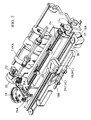
- Fig. 2 is an outward perspective view showing an example of the ink-jet recording apparatus equipped with mechanisms for performing the above-mentioned processes.
- numeral 20 indicates a recording head of the cartridge IJC having a group of nozzles for ejecting ink onto the recording surface of a recording paper fed onto a platen 24.
- Numeral 16 indicates a carriage HC for holding the recording head 20.
- the carriage 16 is connected with a part of a driving belt 18 for transmitting the driving power of a driving motor 17, and is slidable on two guide shafts 19A and 19B arranged parallel to each other, whereby a reciprocating movement of the recording head 20 is possible over the entire width of the recording paper.
- the recording head 20 records images corresponding to the received data on the recording paper, which is fed by a predetermined amount at the completion of each main scanning, thereby effecting a sub-scanning.
- Numeral 26 indicates a head function recovery device, which is arranged at one end of the movement path of the recording head 20, for example, at a position opposed to the home position.
- the head function recovery device 26 is operated by the driving force of a motor 22, transmitted through a transmission mechanism 23, thereby effecting a capping operation on the recording head 20.
- An appropriate suction means e.g., a suction pump
- An appropriate suction means provided inside the head function recovery device 26 performs an ink sucking operation (a recovery operation through suction of ink) in association with the capping operation of a capping section 26A of the head function recovery device 26 performed on the recording head 20, whereby an ejecting function recovery process is effected by removing the viscous ink remaining in the discharge nozzles.
- capping is also effected after the completion of each recording operation, etc., thereby protecting the recording head 20.
- This ejecting function recovery process is conducted when power is turned on, when the recording head is replaced with a new one, when no recording is to be performed for a certain period of time, etc.
- Numeral 31 indicates a blade which is arranged on a side surface of the head function recovery device 26 and which constitutes a wiping member formed of silicon rubber.
- the blade 31 is retained in a cantilever-like fashion by a blade retaining member 31A, and is operated, like the head function recovery device 26, by the motor 22 and the transmission mechanism 23 in such a way as to be engaged with the ejection surface of the recording head 20.
- This makes it possible for the blade 31 to be engaged with the ejection surface of the recording head 20 with an appropriate timing during a recording operation of the recording head 20 or after an ejecting function recovery process is performed by the head function recovery device 26, thereby removing dew, moisture, dust, etc. from the ejection surface of the recording head 20.
- Fig. 3 shows the electrical system configuration of an image forming apparatus according to an embodiment of the present invention.
- numeral 101 indicates a facsimile control section consisting of a microprocessor, etc. It is composed of a CPU (central processing unit) 104, a ROM (read only memory) 103, a RAM (random access memory) 102 etc., and controls the input and output of images and all of the communication processes.
- the ROM 103 stores a control program which will be described below.
- the RAM 102 is used as a work area for the CPU 104 and, further, stores image data buffers, "printing request flags" which will be described below, printing modes, etc.
- the input and output of images are effected by a reading section 100 and a recording section 111. That is, the reading of original image data is performed by the reading section 100, which is composed of a CCD (chargecoupled device) sensor, an original feeding system, etc. Received image data and image data read by the reading section 100 at the time of copying are printed on paper by the recording section 111, which includes an ink-jet printer (the recording apparatus IJRA as described with reference to Figs. 1 and 2).
- the recording section 111 which includes an ink-jet printer (the recording apparatus IJRA as described with reference to Figs. 1 and 2).
- connection with a communication line, such as a telephone line, and the input and output of data are effected by a modem 105 and an NCU (net control unit) 106.
- a telephone 116 for calls and manual control is connected to the NCU 106.
- image data is input through the NCU 106 and the modem 105 and stored in the RAM 102.
- the control means of the recording section 111 includes a CPU 114, a ROM 113 for storing a CPU control program and a character generator, and a RAM 112 used as a work area for the CPU, command buffer and print buffer.
- This control means controls a carriage motor 9, a paper feed motor 10, and a semi-multi head 11 (corresponding to the head 20 in Figs. 1 and 2).
- the carriage motor 9 is a stepping motor for causing the carriage 16, on which the cartridge 21 (IJC) is mounted, to move in the main scanning direction.
- the paper feed motor 10, which is also a stepping motor, feeds the recording paper in the sub-scanning direction, which is substantially perpendicular to the main scanning direction, after the completion of each main scanning.
- the semi-multi head 11 has several tens to several hundreds of nozzles arranged along the sub-scanning direction (64 nozzles in this embodiment, providing a resolution of 360 dpi), and is adapted to record one page of information on the recording paper by performing the main scanning a plurality of times.
- the data stored in the RAM 102 is transferred by the facsimile control section 101 as raw data (uncoded data) and stored in the RAM 112 in the form of band-like, one-main-scanning data corresponding to the number of nozzles on the semi-multi head 11.
- This band-like data for each line in the main scanning direction is transferred from the RAM 112 to the semi-multi head 11, thereby effecting recording.
- Numeral 110 indicates a switch which is switchable in accordance with the control performed by the facsimile control section 111.
- the switch When the switch is set to the position a , data received in facsimile communications is transmitted to the recording section 111 for printing.
- the switch When the switch is set to the position b, printing data from a computer, connected to a connector 115 is transmitted to the recording section 111 to be printed.
- the facsimile control section 101 transmits not only image data but also commands, which will be described below, to the recording section 111.
- the input data from the connector 115 is input to the switch 110 and, at the same time, it is also input to the facsimile control section 101, whereby it is possible for the facsimile control section 101 to detect, when the switch 110 is at the position b, that printing commands, printing data, etc. are being transmitted from the connector 115 to the recording section 111.
- Fig. 4 is a plan view of an operation panel 107, which has a facsimile operating section 108 and a printer operating section 109.
- the facsimile operating section 108 includes ten keys 131 for entering telephone numbers, various function keys 132, a printer key 121 for switching the operation mode between the facsimile and printer modes, and an LCD display 123 for displaying telephone numbers, time of day, etc.
- the printer operating section 109 includes a printing mode key 126 for enabling the user to designate the printing mode of the recording section 111. The printing mode is changed when the printing mode key 126 is operated at the time that the recording section 111 is in the printer mode. Further, the printer operating section includes displays 128 and 129 for displaying the current printing mode.
- the apparatus of this embodiment has an answering machine function. By depressing an answering machine key 122, the apparatus operates as an answering machine.
- the operation panel 107 is provided with an answering operation section 120 for realizing the answering machine function.
- the printer operating section 109 and the answering operation section 120 are provided with a cover (not shown) which can be opened and closed.
- the printing mode can be selected from the following three modes: an SHQ (super high quality) mode (hereinafter referred to as the "one direction printing mode”), an HQ (high quality) mode (hereinafter referred to as the "normal mode”), and an HS (high speed) mode (hereinafter referred to as the "draft”) mode.
- SHQ super high quality
- normal mode high quality
- HS high speed
- the printing mode key 126 When the printing mode key 126 is depressed, these three printing modes can be changed in a cyclic manner from one to the other to enable the user to select the desired mode.
- the CPU 114 effects a printing operation by moving the carriage 16 in the forward direction only, causing the carriage to return and the recording paper to be fed by one band (line) after each forward movement. By repeating these operations, one page of data is recorded. Due to this arrangement, it is possible to eliminate the deviation in ink ejection points which occurs when the carriage is moved in different directions, thereby making it possible to effect high-quality recording.
- This one direction printing mode is selected when bit image data transmitted from a host computer is to be printed.
- the CPU 114 causes the carriage to return after each forward movement of the carriage. However, after the feeding of the recording paper, the CPU 114 performs a printing operation also in the returning direction by reversely transferring band-like data to the head 11. Thus, it controls the recording section so that a recording operation can be performed by the movement of the carriage 16 in either direction.
- the CPU 114 transfers data from the RAM 112 to the head 11 after thinning the data out in such a way that any two dots adjacent to each other in the main scanning direction are not printed, and the speed at which the carriage is moved by the carriage motor 9 is increased (that is, the step cycle of the motor is increased).
- the increase in the recording speed in the draft mode is due to the above-described thinning-out recording contributing to a reduction in the recording period.
- it takes a certain amount of time (refill time) before the nozzles are refilled with ink after each ejection for effecting printing.
- the apparatus is forcibly set to the normal printing mode, to perform printing independently of the operating section 109 for operating the recording section.
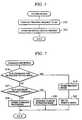
- the facsimile control section 101 conducts a multitask operation, executing a reception task as shown in Fig. 5 and a printing task as shown in Fig. 6 on a time sharing basis.
- the reception task operation of Fig. 5 will be described.
- the reception task is started, in which the procedure advances to step S22, where the "printing request flag" of the RAM 102, which indicates that received image data exists in the memory, is turned ON, and, in step S23, the received image data is stored in the RAM 102.
- the printing task is constantly in operation to monitor the state of the printer key. Further, when the "printing request flag" is turned ON, it starts printing.
- step S1 a judgment is made in step S1 as to whether the printer key has been depressed. If the key is found to have been depressed, the procedure advances to step S2 to effect operation mode switching (between the facsimile and printer modes) of the recording section 111.
- step S2 the current operation mode is checked. If the current operation mode is the printer mode, the procedure advances to step S5, where the switch 110 is switched to the position a so that the commands from the facsimile control section 101 can be transmitted to the recording section 111. Subsequently, in step S6, a command for transition to the facsimile mode is transmitted to the recording section 111. After that, the recording section 111 operates as the recording section of the facsimile apparatus.
- step S2 If, in step S2, the current operation mode is found to be the facsimile mode, the procedure advances to step S3, where a command for cancelling the facsimile mode is transmitted to the recording section 111. Then, in step S4, the switch 110 is switched to the position b. After that, the printing commands from the computer, which is connected to the connector 115, are transmitted to the recording section 111, which then operates as a printer.
- step S7 the "printing request flag" in the RAM 102 is checked.
- the procedure returns to step S1.
- the procedure advances to step S8, where the current operation mode is checked. If the current operation mode is found to be the facsimile mode, the received image data in the RAM 102 is sent, in step S15, to the recording section 111, whereby the received images are printed, and then the procedure returns to step S1.
- step S8 When, in step S8, the current operation mode is found to be the printer mode, it is checked, in step S9, whether any data is being sent from the connector 115 to the recording section 111. If data is being sent to the recording section, it is judged that printing is being performed, and step S8 is looped. It no printing is being performed, the procedure advances to step S10, where the switch 110 is switched to the position a . Subsequently, in step S11, a command for transition to the facsimile mode is sent to the recording section 111. Next, in step S12, images received in facsimile communications are printed, as in step S15. In step S13, a command for cancelling the facsimile mode is sent to the recording section 111.
- step S14 the switch 110 is returned to the position b.
- a "busy" signal is supplied to the host computer.
- steps S13 and S14 the recording section 111 is restored to the printer mode, and the procedure returns to step S1 to repeat the above operations.
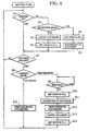
- Fig. 7 is an operation flowchart for the recording section 111.
- step S16 When a command is transmitted from the facsimile control section 101 by way of the switch 110, the control procedure for the recording section 111 advances to step S16. If, in step S16, the command transmitted is a command for transition to the facsimile mode, the procedure advances to step S19, where the printing mode which has been used in the printer mode up to the present is stored in the RAM 112. Then, in step S21, the printing mode is set to the normal mode for reciprocative printing, thereby commanding the command receiving operation. If, in step S16, the command transmitted is not a mode for transition to the facsimile mode, the procedure advances to step S17, where it is checked whether the command is a facsimile mode cancelling command.
- step S20 the printing mode which has been used in the printer mode until the transition to the facsimile mode is read from the RAM 112 to set, for example, the one-direction printing mode, thereby completing the setting operation. If, in step S17, the command transmitted is not a command for cancelling the facsimile mode, the procedure advances to step S18, where processes for other commands are executed to end the operation.
- the present apparatus it is possible to perform printing in a printing mode that is most suitable for the operation mode (which is either the printer mode or the facsimile mode) of the recording section. That is, when the apparatus is used as a printer, the user can select a desired printing mode from three printing modes, a high-quality mode, normal mode, and draft mode, and high quality printing of image data can be effected by one direction printing (the high-quality mode).
- the printing mode is set to the normal mode, thereby enabling images received in facsimile communications to be printed at a higher speed without causing any extreme deterioration in image quality.
- step S9 when the result of step S7 is "YES".
- the facsimile control section can control the recording section. That is, the operation of the recording section of Fig. 6 can also be executed as one of the tasks of the facsimile control section.
- the main control section for controlling the transmission and reception of data and the operation display section and the recording control section for controlling recording operations
- the main control section it is also possible for the main control section to be designed so as to be capable of controlling all operations including the recording operations.
- this ink-jet recording system can be advantageously applied to the on-demand type recording apparatus, in which at least one driving signal causing a rapid rise in temperature beyond a boiling point in accordance with the information to be recorded, is applied to electrothermal conversion members arranged in correspondence with a sheet retaining liquid (ink) or with a liquid path.
- a driving signal causing a rapid rise in temperature beyond a boiling point in accordance with the information to be recorded
- electrothermal conversion members arranged in correspondence with a sheet retaining liquid (ink) or with a liquid path.
- a full-line type recording head having a length corresponding to the width of the largest recording medium that can be used in the associated recording apparatus can be formed by combining a plurality of recording heads so as to satisfy the length requirement therefor, as disclosed in the specifications mentioned above.
- such a full-line type recording head can be formed as a single recording head in the form of an integral unit.
- the present invention can be effectively applied to a replaceable-chip-type recording head, which is attached to the associated recording apparatus body so as to be electrically connected thereto and supplied with ink therefrom. Further, the present invention can also be effectively applied to a cartridge-type recording head, which is integrally provided with an ink tank.
- a function recovery means for the recording head is desirable since this will further stabilize the effects of the present invention.
- the ink used may be of such a type which does not liquify until heat energy is imparted thereto and which instantly starts to solidify upon reaching the recording medium.
- Such a type of ink may be retained in the form of a liquid or solid in recesses of a porous sheet or in through-holes in such a way as to be opposed to the electrothermal conversion members, as described in Japanese Patent Laid-Open Nos. 54-56847 and 60-71260.
- the above-described types of ink can be most effectively applied to an apparatus of the system utilizing film boiling as mentioned above.
- the present invention is not restricted to the ink-jet system utilizing heat energy, but is also applicable to the ink-jet system utilizing piezoelectric elements, etc.
Landscapes
- Engineering & Computer Science (AREA)
- Multimedia (AREA)
- Signal Processing (AREA)
- General Engineering & Computer Science (AREA)
- Computing Systems (AREA)
- Physics & Mathematics (AREA)
- Theoretical Computer Science (AREA)
- General Physics & Mathematics (AREA)
- Mathematical Physics (AREA)
- Ink Jet (AREA)
- Facsimiles In General (AREA)
- Accessory Devices And Overall Control Thereof (AREA)
- Control Or Security For Electrophotography (AREA)
- Particle Formation And Scattering Control In Inkjet Printers (AREA)
- Record Information Processing For Printing (AREA)
- Fax Reproducing Arrangements (AREA)
Claims (13)
- Appareil de formation d'images d'un type qui possède une fonction de télécopie, par laquelle il enregistre des données d'image reçues lors de communications de télécopie et une fonction d'imprimante, par laquelle il enregistre des données d'images délivrées par un ordinateur central, ledit appareil de formation d'images comprenant :une section de commande de télécopie pour commander la fonction de télécopie ;un moyen d'enregistrement pour l'enregistrement de données d'images, ledit moyen d'enregistrement comprenant une pluralité de modes d'impression de différentes qualités d'image ; etun moyen de réception pour recevoir des données d'image de télécopie, dans lequel ladite section de commande de télécopie génère et envoie audit moyen d'enregistrement une commande pour amener ledit moyen d'enregistrement à régler un mode d'impression spécifique lorsque les données d'image de télécopie reçues par ledit moyen de réception doivent être enregistrées par ledit moyen de réception de sorte que le mode d'impression spécifique est réglé dans ledit moyen d'enregistrement, indépendamment de tout mode d'impression réglé auparavant dans ledit moyen d'enregistrement.
- Appareil de formation d'images selon la revendication 1, dans lequel ladite pluralité de modes d'impression comprend au moins l'un d'un mode rapide et d'un mode à haute qualité.
- Appareil de formation d'images selon la revendication 2, dans lequel ledit mode rapide est un mode d'enregistrement avec éclaircissage, dans lequel des données d'images sont enregistrées sous une forme éclaircie.
- Appareil de formation d'images selon la revendication 2, dans lequel ledit moyen d'enregistrement comprend : une tête d'enregistrement qui est équipée d'une pluralité d'éléments d'enregistrement ; et un moyen de déplacement pour exécuter un balayage principal au moyen d'un déplacement en va-et-vient de ladite tête d'enregistrement par rapport à un support d'enregistrement, ledit mode de haute qualité étant un mode d'enregistrement dans une direction, dans lequel le balayage principal est exécuté par un déplacement de ladite tête d'enregistrement dans une direction dudit déplacement en va-et-vient.
- Appareil de formation d'images selon la revendication 4, dans lequel ledit mode spécifique est un mode d'enregistrement dans deux directions, dans lequel le balayage principal est exécuté au moyen d'un déplacement de ladite tête d'enregistrement dans les deux directions dudit déplacement en va-et-vient.
- Appareil de formation d'images selon la revendication 1, comprenant en outre : un moyen de réglage du mode de fonctionnement pour régler l'appareil sur un mode de télécopie pour réaliser la fonction de télécopie, et sur un mode d'imprimante pour réaliser la fonction d'imprimante.
- Appareil de formation d'images selon la revendication 6, dans lequel ledit moyen de réglage du mode de fonctionnement exécute le réglage du mode de fonctionnement en fonction d'une commande délivrée par l'ordinateur central.
- Appareil de formation d'images selon la revendication 6, dans lequel ledit moyen de réglage du mode de fonctionnement règle le mode de fonctionnement sur le mode de télécopie en réponse à une opération manuelle exécutée par un opérateur et/ou à un appel envoyé à partir d'une ligne.
- Appareil de formation d'images selon la revendication 8, dans lequel ledit moyen de réglage du mode de fonctionnement règle automatiquement l'appareil sur ledit mode d'imprimante en réponse à l'exécution de l'enregistrement des données d'images de télécopie reçues par ledit moyen de réception.
- Appareil de formation d'images selon la revendication 6, dans lequel ladite section de commande de télécopie génère et envoie audit moyen d'enregistrement la commande pour amener ledit moyen d'enregistrement à régler ledit mode d'impression spécifique en réponse au réglage de l'appareil sur le mode de télécopie par ledit moyen de réglage du mode de fonctionnement.
- Appareil de formation d'images selon la revendication 1, dans lequel ledit moyen d'enregistrement enregistre des images sur un support d'enregistrement au moyen de l'éjection de gouttelettes d'encre par des gicleurs de décharge moyennant l'utilisation d'une énergie d'éjection produite en fonction de données d'image devant être enregistrées.
- Appareil de formation d'images selon la revendication 11, dans lequel ledit moyen d'enregistrement éjecte des gouttelettes d'encre en provoquant des modifications d'un état de l'encre au moyen d'une énergie thermique.
- Appareil de formation d'images selon la revendication 12, dans lequel ledit moyen d'enregistrement comprend : une tête d'enregistrement, qui est équipée d'une pluralité d'éléments d'enregistrement ; et un moyen de déplacement pour l'exécution d'un balayage principal au moyen d'un déplacement en va-et-vient de ladite tête d'enregistrement par rapport au support d'enregistrement.
Applications Claiming Priority (2)
| Application Number | Priority Date | Filing Date | Title |
|---|---|---|---|
| JP5013877A JPH06233090A (ja) | 1993-01-29 | 1993-01-29 | 画像形成装置 |
| JP13877/93 | 1993-01-29 |
Publications (2)
| Publication Number | Publication Date |
|---|---|
| EP0608880A1 EP0608880A1 (fr) | 1994-08-03 |
| EP0608880B1 true EP0608880B1 (fr) | 1999-05-06 |
Family
ID=11845450
Family Applications (1)
| Application Number | Title | Priority Date | Filing Date |
|---|---|---|---|
| EP94101197A Expired - Lifetime EP0608880B1 (fr) | 1993-01-29 | 1994-01-27 | Appareil pour la formation d'images |
Country Status (5)
| Country | Link |
|---|---|
| US (2) | US5844690A (fr) |
| EP (1) | EP0608880B1 (fr) |
| JP (1) | JPH06233090A (fr) |
| DE (1) | DE69418221T2 (fr) |
| ES (1) | ES2131596T3 (fr) |
Families Citing this family (9)
| Publication number | Priority date | Publication date | Assignee | Title |
|---|---|---|---|---|
| JPH06233090A (ja) * | 1993-01-29 | 1994-08-19 | Canon Inc | 画像形成装置 |
| US6559960B2 (en) | 1993-01-29 | 2003-05-06 | Canon Kabushiki Kaisha | Image processing apparatus and method that sets a printing mode based on image data to be printed |
| JPH0924645A (ja) * | 1995-07-12 | 1997-01-28 | Nec Corp | プリンタ装置 |
| JP3794177B2 (ja) * | 1998-10-21 | 2006-07-05 | コニカミノルタビジネステクノロジーズ株式会社 | 画像形成装置 |
| JP4174696B2 (ja) * | 1998-11-11 | 2008-11-05 | ソニー株式会社 | 記録装置および方法、並びに記録媒体 |
| JP2001350365A (ja) * | 2000-06-05 | 2001-12-21 | Minolta Co Ltd | 画像形成装置 |
| JP4497807B2 (ja) * | 2002-11-26 | 2010-07-07 | キヤノン株式会社 | 記録装置および該装置の制御方法 |
| US7460921B2 (en) * | 2004-09-28 | 2008-12-02 | Markem Corporation | Dynamic marking system |
| JP5488622B2 (ja) * | 2012-01-16 | 2014-05-14 | コニカミノルタ株式会社 | 画像形成装置 |
Family Cites Families (26)
| Publication number | Priority date | Publication date | Assignee | Title |
|---|---|---|---|---|
| CA1127227A (fr) * | 1977-10-03 | 1982-07-06 | Ichiro Endo | Procede d'enregistrement a jet liquide et appareil d'enregistrement |
| JPS5936879B2 (ja) * | 1977-10-14 | 1984-09-06 | キヤノン株式会社 | 熱転写記録用媒体 |
| US4330787A (en) * | 1978-10-31 | 1982-05-18 | Canon Kabushiki Kaisha | Liquid jet recording device |
| US4345262A (en) * | 1979-02-19 | 1982-08-17 | Canon Kabushiki Kaisha | Ink jet recording method |
| US4463359A (en) * | 1979-04-02 | 1984-07-31 | Canon Kabushiki Kaisha | Droplet generating method and apparatus thereof |
| US4313124A (en) * | 1979-05-18 | 1982-01-26 | Canon Kabushiki Kaisha | Liquid jet recording process and liquid jet recording head |
| US4558333A (en) * | 1981-07-09 | 1985-12-10 | Canon Kabushiki Kaisha | Liquid jet recording head |
| US4401991A (en) * | 1981-10-08 | 1983-08-30 | International Business Machines Corporation | Variable resolution, single array, interlace ink jet printer |
| JPS59123670A (ja) * | 1982-12-28 | 1984-07-17 | Canon Inc | インクジエツトヘツド |
| JPS59138461A (ja) * | 1983-01-28 | 1984-08-08 | Canon Inc | 液体噴射記録装置 |
| JPS6071260A (ja) * | 1983-09-28 | 1985-04-23 | Erumu:Kk | 記録装置 |
| US4885641A (en) * | 1985-06-17 | 1989-12-05 | Canon Kabushiki Kaisha | Image communication apparatus |
| JP2733220B2 (ja) * | 1986-09-30 | 1998-03-30 | シャープ株式会社 | 複合型画像処理装置 |
| JP2740180B2 (ja) * | 1987-05-09 | 1998-04-15 | 株式会社リコー | 複写装置 |
| JPH0814827B2 (ja) * | 1987-11-11 | 1996-02-14 | キヤノン株式会社 | 情報処理装置 |
| US4947345A (en) * | 1989-07-25 | 1990-08-07 | Xerox Corporation | Queue management system for a multi-function copier, printer, and facsimile machine |
| JP2910116B2 (ja) * | 1990-01-25 | 1999-06-23 | ブラザー工業株式会社 | インターフェース付ファクシミリ装置 |
| JP3068637B2 (ja) * | 1990-09-10 | 2000-07-24 | キヤノン株式会社 | シリアル記録装置 |
| JPH04128064A (ja) * | 1990-09-19 | 1992-04-28 | Koufu Nippon Denki Kk | 印字装置 |
| US5266996A (en) * | 1990-10-19 | 1993-11-30 | Minolta Camera Kabushiki Kaisha | Recording apparatus |
| JPH04279367A (ja) * | 1991-03-08 | 1992-10-05 | Hitachi Ltd | シリアルドットプリンタの間引き印字制御方式 |
| JP2661416B2 (ja) * | 1991-06-29 | 1997-10-08 | ブラザー工業株式会社 | 印字システム |
| US5815280A (en) * | 1991-10-09 | 1998-09-29 | Canon Kabushiki Kaisha | Image recording apparatus with prioritization of input |
| JP3195398B2 (ja) * | 1992-02-05 | 2001-08-06 | キヤノン株式会社 | ファクシミリ装置およびその制御方法 |
| US5469373A (en) * | 1992-02-14 | 1995-11-21 | Canon Kabushiki Kaisha | Printing apparatus and method that discriminates which analyzer should analyze information |
| JPH06233090A (ja) * | 1993-01-29 | 1994-08-19 | Canon Inc | 画像形成装置 |
-
1993
- 1993-01-29 JP JP5013877A patent/JPH06233090A/ja active Pending
-
1994
- 1994-01-27 DE DE69418221T patent/DE69418221T2/de not_active Expired - Lifetime
- 1994-01-27 EP EP94101197A patent/EP0608880B1/fr not_active Expired - Lifetime
- 1994-01-27 ES ES94101197T patent/ES2131596T3/es not_active Expired - Lifetime
-
1997
- 1997-09-11 US US08/927,802 patent/US5844690A/en not_active Expired - Lifetime
-
1998
- 1998-10-29 US US09/182,005 patent/US6342949B1/en not_active Expired - Lifetime
Also Published As
| Publication number | Publication date |
|---|---|
| DE69418221T2 (de) | 2000-01-05 |
| JPH06233090A (ja) | 1994-08-19 |
| US5844690A (en) | 1998-12-01 |
| DE69418221D1 (de) | 1999-06-10 |
| ES2131596T3 (es) | 1999-08-01 |
| EP0608880A1 (fr) | 1994-08-03 |
| US6342949B1 (en) | 2002-01-29 |
Similar Documents
| Publication | Publication Date | Title |
|---|---|---|
| JP3363515B2 (ja) | 画像通信装置 | |
| JP3507102B2 (ja) | ファクシミリ装置とその印刷制御方法 | |
| EP0608880B1 (fr) | Appareil pour la formation d'images | |
| US6168320B1 (en) | Printing apparatus and method, and facsimile apparatus comprising the apparatus | |
| EP0576285B1 (fr) | Méthode et appareil pour l'enregistrement à jet d'encre | |
| JP3205082B2 (ja) | 画像形成方法及び装置 | |
| US7315393B2 (en) | Printing system, printer driver, and printing method | |
| US6880905B2 (en) | Image printing apparatus and control method therefor | |
| EP1355264B1 (fr) | Appareil et procédé d'impression | |
| US7500727B2 (en) | Ink jet printing apparatus and ink jet printing method | |
| US6559960B2 (en) | Image processing apparatus and method that sets a printing mode based on image data to be printed | |
| EP0552909B1 (fr) | Dispositif de reproduction d'images | |
| US6341834B1 (en) | Recording apparatus and control method thereof | |
| US5563712A (en) | Image recording apparatus with transmission time setting feature | |
| US7889380B2 (en) | Printing apparatus and control method therefor | |
| JPH07131614A (ja) | 画像記録方法及び装置及び該装置を用いたファクシミリ装置 | |
| US7359073B2 (en) | Image printing apparatus and control method therefor | |
| US6474775B1 (en) | Ink jet recording apparatus and method for recording with plural nozzle arrays | |
| US5984453A (en) | Recording apparatus and method by time-division drive | |
| JP2001105633A (ja) | 記録装置および記録装置の画像処理方法 | |
| JP3347474B2 (ja) | ファクシミリ装置 | |
| JPH06284238A (ja) | 画像記録装置 | |
| JPH06106719A (ja) | インクジェット記録装置 | |
| JPH05338209A (ja) | カラー画像記録装置 | |
| JPH06127035A (ja) | シリアル記録装置 |
Legal Events
| Date | Code | Title | Description |
|---|---|---|---|
| PUAI | Public reference made under article 153(3) epc to a published international application that has entered the european phase |
Free format text: ORIGINAL CODE: 0009012 |
|
| AK | Designated contracting states |
Kind code of ref document: A1 Designated state(s): DE ES FR GB IT |
|
| 17P | Request for examination filed |
Effective date: 19941220 |
|
| 17Q | First examination report despatched |
Effective date: 19970203 |
|
| GRAG | Despatch of communication of intention to grant |
Free format text: ORIGINAL CODE: EPIDOS AGRA |
|
| GRAG | Despatch of communication of intention to grant |
Free format text: ORIGINAL CODE: EPIDOS AGRA |
|
| GRAG | Despatch of communication of intention to grant |
Free format text: ORIGINAL CODE: EPIDOS AGRA |
|
| GRAH | Despatch of communication of intention to grant a patent |
Free format text: ORIGINAL CODE: EPIDOS IGRA |
|
| GRAH | Despatch of communication of intention to grant a patent |
Free format text: ORIGINAL CODE: EPIDOS IGRA |
|
| GRAA | (expected) grant |
Free format text: ORIGINAL CODE: 0009210 |
|
| AK | Designated contracting states |
Kind code of ref document: B1 Designated state(s): DE ES FR GB IT |
|
| REF | Corresponds to: |
Ref document number: 69418221 Country of ref document: DE Date of ref document: 19990610 |
|
| ET | Fr: translation filed | ||
| REG | Reference to a national code |
Ref country code: ES Ref legal event code: FG2A Ref document number: 2131596 Country of ref document: ES Kind code of ref document: T3 |
|
| PLBE | No opposition filed within time limit |
Free format text: ORIGINAL CODE: 0009261 |
|
| STAA | Information on the status of an ep patent application or granted ep patent |
Free format text: STATUS: NO OPPOSITION FILED WITHIN TIME LIMIT |
|
| 26N | No opposition filed | ||
| REG | Reference to a national code |
Ref country code: GB Ref legal event code: IF02 |
|
| PG25 | Lapsed in a contracting state [announced via postgrant information from national office to epo] |
Ref country code: IT Free format text: LAPSE BECAUSE OF NON-PAYMENT OF DUE FEES Effective date: 20100127 |
|
| PGFP | Annual fee paid to national office [announced via postgrant information from national office to epo] |
Ref country code: IT Payment date: 20120110 Year of fee payment: 19 |
|
| PGFP | Annual fee paid to national office [announced via postgrant information from national office to epo] |
Ref country code: DE Payment date: 20130131 Year of fee payment: 20 Ref country code: GB Payment date: 20130123 Year of fee payment: 20 Ref country code: FR Payment date: 20130214 Year of fee payment: 20 Ref country code: ES Payment date: 20130115 Year of fee payment: 20 |
|
| REG | Reference to a national code |
Ref country code: DE Ref legal event code: R071 Ref document number: 69418221 Country of ref document: DE |
|
| REG | Reference to a national code |
Ref country code: GB Ref legal event code: PE20 Expiry date: 20140126 |
|
| REG | Reference to a national code |
Ref country code: ES Ref legal event code: FD2A Effective date: 20140407 |
|
| PG25 | Lapsed in a contracting state [announced via postgrant information from national office to epo] |
Ref country code: GB Free format text: LAPSE BECAUSE OF EXPIRATION OF PROTECTION Effective date: 20140126 Ref country code: DE Free format text: LAPSE BECAUSE OF EXPIRATION OF PROTECTION Effective date: 20140128 |
|
| PG25 | Lapsed in a contracting state [announced via postgrant information from national office to epo] |
Ref country code: ES Free format text: LAPSE BECAUSE OF EXPIRATION OF PROTECTION Effective date: 20140128 |