EP0608945B1 - Sterndetektor mit ladungsgekoppelter Matrix, Verfahren zur Detektion und Anwendung zur Neueinstellung eines Raumfahrzeuges - Google Patents
Sterndetektor mit ladungsgekoppelter Matrix, Verfahren zur Detektion und Anwendung zur Neueinstellung eines Raumfahrzeuges Download PDFInfo
- Publication number
- EP0608945B1 EP0608945B1 EP94200151A EP94200151A EP0608945B1 EP 0608945 B1 EP0608945 B1 EP 0608945B1 EP 94200151 A EP94200151 A EP 94200151A EP 94200151 A EP94200151 A EP 94200151A EP 0608945 B1 EP0608945 B1 EP 0608945B1
- Authority
- EP
- European Patent Office
- Prior art keywords
- image
- star
- window
- sight
- array
- Prior art date
- Legal status (The legal status is an assumption and is not a legal conclusion. Google has not performed a legal analysis and makes no representation as to the accuracy of the status listed.)
- Expired - Lifetime
Links
Images


Classifications
-
- G—PHYSICS
- G01—MEASURING; TESTING
- G01S—RADIO DIRECTION-FINDING; RADIO NAVIGATION; DETERMINING DISTANCE OR VELOCITY BY USE OF RADIO WAVES; LOCATING OR PRESENCE-DETECTING BY USE OF THE REFLECTION OR RERADIATION OF RADIO WAVES; ANALOGOUS ARRANGEMENTS USING OTHER WAVES
- G01S3/00—Direction-finders for determining the direction from which infrasonic, sonic, ultrasonic or electromagnetic waves, or particle emission, not having a directional significance, are being received
- G01S3/78—Direction-finders for determining the direction from which infrasonic, sonic, ultrasonic or electromagnetic waves, or particle emission, not having a directional significance, are being received using electromagnetic waves other than radio waves
- G01S3/782—Systems for determining direction or deviation from predetermined direction
- G01S3/785—Systems for determining direction or deviation from predetermined direction using adjustment of orientation of directivity characteristics of a detector or detector system to give a desired condition of signal derived from that detector or detector system
- G01S3/786—Systems for determining direction or deviation from predetermined direction using adjustment of orientation of directivity characteristics of a detector or detector system to give a desired condition of signal derived from that detector or detector system the desired condition being maintained automatically
- G01S3/7867—Star trackers
-
- B—PERFORMING OPERATIONS; TRANSPORTING
- B64—AIRCRAFT; AVIATION; COSMONAUTICS
- B64G—COSMONAUTICS; VEHICLES OR EQUIPMENT THEREFOR
- B64G1/00—Cosmonautic vehicles
- B64G1/22—Parts of, or equipment specially adapted for fitting in or to, cosmonautic vehicles
- B64G1/24—Guiding or controlling apparatus, e.g. for attitude control
- B64G1/36—Guiding or controlling apparatus, e.g. for attitude control using sensors, e.g. sun-sensors, horizon sensors
- B64G1/361—Guiding or controlling apparatus, e.g. for attitude control using sensors, e.g. sun-sensors, horizon sensors using star sensors
-
- G—PHYSICS
- G01—MEASURING; TESTING
- G01C—MEASURING DISTANCES, LEVELS OR BEARINGS; SURVEYING; NAVIGATION; GYROSCOPIC INSTRUMENTS; PHOTOGRAMMETRY OR VIDEOGRAMMETRY
- G01C21/00—Navigation; Navigational instruments not provided for in groups G01C1/00 - G01C19/00
- G01C21/02—Navigation; Navigational instruments not provided for in groups G01C1/00 - G01C19/00 by astronomical means
- G01C21/025—Navigation; Navigational instruments not provided for in groups G01C1/00 - G01C19/00 by astronomical means with the use of startrackers
-
- H—ELECTRICITY
- H04—ELECTRIC COMMUNICATION TECHNIQUE
- H04N—PICTORIAL COMMUNICATION, e.g. TELEVISION
- H04N25/00—Circuitry of solid-state image sensors [SSIS]; Control thereof
- H04N25/40—Extracting pixel data from image sensors by controlling scanning circuits, e.g. by modifying the number of pixels sampled or to be sampled
- H04N25/44—Extracting pixel data from image sensors by controlling scanning circuits, e.g. by modifying the number of pixels sampled or to be sampled by partially reading an SSIS array
- H04N25/443—Extracting pixel data from image sensors by controlling scanning circuits, e.g. by modifying the number of pixels sampled or to be sampled by partially reading an SSIS array by reading pixels from selected two-dimensional [2D] regions of the array, e.g. for windowing or digital zooming
Definitions
- the present invention relates to a star finder for analysis of the image of at least one luminous object, comprising a sensor of position which implements an element detector matrix charge transfer photosensitive (DTC) and image memory in which is transferred, after each integration time Ti and during a reading time T1 in the form of digital samples, the image detected by said matrix and where it replaces the previous image.
- DTC element detector matrix charge transfer photosensitive
- the invention also relates to a method of detection by accumulation of thumbnails defined by variable position windows, on the DTC matrix, and it advantageously applies to stellar registration of a maneuvering satellite.
- a read register then receives, always by charge transfer, line by line, the information in the memory area, and then these information is provided in analog form to an output stage at from which they can be read pixel by pixel so that they can reconstruct the image previously obtained on the photosensitive area under in the form of digital samples, stored in an image memory.
- search mode a first mode of operation of the device, called search mode, consists in defining, in a sub-matrix the so-called search window contained in the matrix described more top, the position, to the nearest pixel, of the luminous object sought after, being understood that the search window has been previously defined from a sensor inertial, for example, installed on the same device as the sighting of the luminous object (generally on a spacecraft).
- a DTC matrix star finder is designed to cover a square or rectangular field of a few degrees over a few degrees, a degree itself being covered by about 100 pixels on the matrix.
- the measurement frequency is limited by the intensity of the star to be measured.
- the aim, in particular the phase of detection, then becomes impossible, the drag effect being too marked, in other words, the available energy being spread over too many pixels.
- a known solution to solve the technical problem indicated in the previous paragraph is to use as stellar sights image dissecting tubes.
- Such tubes allow you to aim for stars of greater magnitude, of the order of 7 or 8, and of angular movement faster than DTC viewfinders: a small measurement module a star tracking filter on the tube allows a servo-control of the position of the axis of the tube on the direction of the star.
- the image dissecting tube has the defects inherent in a analog technology: complexity, fragility, weight, large dimensions, so many disadvantages, moreover, increased in a spatial context.
- An object of the invention is to detect weakly stars luminous with rapid angular movements by means of a DTC matrix viewfinder.
- Another purpose is to allow an (aero) spacecraft to readjust its position on dimly lit stars at using DTC array finders mounted on platforms directly attached to said spacecraft.
- these aims are achieved by virtue of the fact that the star finder indicated in the first paragraph is remarkable in that, for the detection and analysis of the image of dimly luminous objects in rapid movement, said finder stars having, at any time, available, as for the displacement of said luminous object relative to said position sensor, assistance information provided by reference frame reference means linked to said luminous object, it further comprises a memory section digital window dedicated to the storage of a window, containing the image of said light object, of predetermined dimensions and of variable position on said detector matrix, selection means for, during each integration time Ti n + 1 , select in the image contained in memory, said readjusted window relating to the previous integration time Ti n , adding means for adding, pixel sample by ec pixel swivel, said window readjusted to the window previously contained in said digital memory section and to fill the latter with the result of addition thus obtained, before the end of the integration of the image integrated at time Ti n + 1 , the total number of windows accumulated, making it possible to obtain a signal
- the invention is primarily based on the idea that, the number of stars of medium magnitude being sufficient to achieve the goals sought, there is no need to use stars that are too large magnitude that would be undetectable by existing DTC matrices, whatever their mode of operation. Furthermore, the invention is made possible by the fact that the search window, sized on the precision in abscissa and ordinate of the position of the star on the matrix, and its displacement, are very small compared to the latter, which allows the accumulation of several tens of windows without leaving the matrix detection.
- the star is pursued, on the matrix, at a frame frequency adapted to the range of motion.
- the signal can then be integrated by addition of thumbnails, one thumbnail per window, over a period of time (period) long enough, on the order of a second, which achieves a trade-off between the desired precision, ie the S / N ratio, and the amplitude of the movement of the star on the matrix.
- the star signal collected at each frame being a priori insufficient to allow a satisfactory detection, the pursuit, which comes down to a selection of successive windows, requires knowing the apparent movement of the star on the detector; this information can be obtained from inertial sensors, consisting either of an inertial unit external to the viewfinder, which continuously provides attitude information directly to the sight, either by one (or two) middle class inertial sensor (s), specific and integrated into said star viewfinder position sensor, which constitutes two possible variants for means of locating repository.
- inertial sensors consisting either of an inertial unit external to the viewfinder, which continuously provides attitude information directly to the sight, either by one (or two) middle class inertial sensor (s), specific and integrated into said star viewfinder position sensor, which constitutes two possible variants for means of locating repository.
- a thumbnail accumulation process that follows precedent is remarkable in that said central unit determines the average position of said star on the matrix of DTC elements by vector addition of the geometric barycenter vector of the P positions of window on said matrix and the coincident energy barycenter vector with the position of the light object analyzed in the thumbnail image of order P.
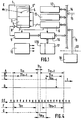
- Figure 1 is the block diagram of a star finder according to the invention.
- Figure 2 is a diagram explaining the addition process of thumbnails made by the star viewfinder of figure 1.
- Figure 3 shows, in A, B and C a thumbnail reconstructed according to the invention, at the rate of a single thumbnail at A, of the cumulation 4 thumbnails in B, and a total of 16 thumbnails in C.
- Figure 4 is an explanatory time diagram of the workflow for processing digital samples representative of the pixels of the DTC matrix of the viewfinder.
- FIG. 5 represents an optical copying device of a mechanical repository in a stellar viewfinder according to the invention.
- Figure 1 is shown schematically a viewfinder of stars proper, referenced 1.
- this viewfinder includes a lens (not shown) which forms a luminous object, more particularly of the star E an image E ', covering approximately 4 pixels on a photosensitive detector 3.
- Detector 3 is a matrix of detectors Photosensitive to Charge Transfer (pixels DTC) placed in substance at focus of the lens.
- This detector is divided into two parts: a first half, the photosensitive zone 4 is intended to receive and detect by integration of photons, the light radiation coming from the object targeted.
- the second half 5 serves as analog memory in which are stored, by charge transfer, for a short time Tt before Ti, the information received by the first half 4 during an integration time Ti.
- the two halves 4 and 5 of the matrix detector 3 have commands for separate charge transfer from a sequencer 6.
- a register of reading 7 then receives, always by line-by-line load transfer under the sequencer 6 command, the information contained in the zone memory and then this information is provided in analog form after amplification through an amplifier 8, to a video chain ensuring the digital conversion of the signal from which they can be read pixel by pixel, for a time Tl, so as to be able to reconstruct the image previously obtained on the photosensitive zone 4, in the form digital samples.
- the image digital is supplied directly to a process image 13.
- the elements already mentioned electronic 6, 9 and 13 indicated above belong to a electronic viewfinder assembly providing all the focusing functions signal and interface.
- This electronics which can be grouped together in a housing integral or not with the viewfinder 1 proper comprises in in addition to a central unit 12 and the associated memories (RAM / PROM) 13 (which serve among other things as image memories), to manage the whole and perform numerical processing (calculations).
- Sequencer 6 generates all the clock signals necessary for the operation of the detector 3 but also to video channel 9 and to the preprocessing of Support information explained below. Power supplies and easements of the whole are symbolized by a block 10 (cooling of the matrix to DTC in particular).
- a common bus 14 allows communication bidirectional between elements 12, 13 and 6. To finish with the classic part of the viewfinder, a bus qualified as: user dialogue bus, 15, is connected to bus 14.
- the viewfinder further comprises, in its part electronics, selection means and addition means, grouped together in a specific unit 16 as well as, associated with the image memory 13, a window memory section itself doubles 17, 170.
- the block of selection-addition 16 is controlled by the sequencer 6. It receives the digital samples from video channel 9, and communicates bidirectionally with memories 13, 17, 170 and with bus 14.
- the viewfinder receives on bus 14, coming from a benchmark locating unit 18, inertial assistance information on a bus 19.
- the unit 18 can be external or internal to the viewfinder, which is symbolized by the broken line 20.
- the assistance information consists of attitude information under the form of increments of angular movement.
- attitude information e.g. attitude information under the form of increments of angular movement.
- the viewfinder is no longer autonomous and it appears mechanical coupling problems such as a rigid connection necessary between the standards of the stellar viewfinder and of the inertial sensor, and of the constraints information relating to the information flow and the transfer times of data.
- the treatment of assistance information from inertial sensors and provided by the bus 19 (figure 1) allows, with a constant drift, to follow the trace of the star on the photosensitive zone 4.
- This treatment essentially consists in a projection in the plane of zone 4 of the apparent movement of the star. In practice, it is the platform supporting the viewfinder that is animated of movement relative to the sky.
- the purpose of the measurement is to determine this drift which represents the projection, on zone 4, of the misalignment between the known position (attitude) of the platform from benchmark locating means (inertial sensors) and its attitude real in the benchmark that constitutes the sky, this last attitude being measured, according to the invention, by adding thumbnails which constitute under successive images of the images formed successively on the area photosensitive 4.
- the assistance thus established makes it possible to move a measurement window 22 which blindly follows the position of the star during each integration in zone 4.
- the selection of each window is performed by unit 16 (figure 1). Indeed, the dimensions of the window, typically 30 square pixels are such that they correspond to the maximum error that can occur on the position of the reconstructed star on zone 4 from assistance information, this theoretical position being in the center of each window such as 22.
- the displacement is limited in fineness to the nearest pixel and is only possible with each frame (with each new signal integration).
- the dimensions of window 22 are determined by the uncertainty about the position of the star, the displacement of this star for the duration of an integration, the diameter of the spot image of the star and the margins necessary to apply the algorithms calculation (first order by adding the corresponding dimensions).
- the integration time Ti of each frame is adapted to the amplitude of the movement during this same period so as to that the energy distribution obtained is optimal, that is to say that the measurement noise is minimal. This optimum corresponds to a displacement 23 (exaggerated in Figure 2), slightly greater than the diameter of the spot image, typically 2 to 3 pixels.
- the thumbnails thus obtained, 25, 26, 27, 28, i.e. the portions of images delimited by the measurement window 22, are superimposed and added successively to each other, as symbolically represented in 30.
- the addition partial is carried out by unit 16 ( Figure 1) and stored in the window storage section 17.
- the coordinates of the windows preferably the abscissa and zero-ordinate pixel of the window
- memory 170 associated with memory 17.
- these coordinates can be immediately added to prepare the following calculations.
- the addition of the thumbnails is continued until obtaining a sufficient S / N ratio to ensure the detection of the position true of the star inside the window.
- the representation made at the top of Figure 2 is purposely inaccurate, for educational purposes.
- the number of windows along this trail is significantly more high, typically 4 to 12 times larger (16 to 50 cumulative images) and the photosensitive zone 4 has dimensions approximately tenfold of those represented (hundreds of pixels on the abscissa and on the ordinate).
- the magnitude of the difference between the expected position and the position real of the star is represented, in 30, by the segment OO ', the point O being the center of the window and the point O 'the energy barycenter of the signal distribution resulting from the addition of the thumbnails. If the amplitude of the difference to be measured is too large, it may be necessary to set performs a preliminary search mode to detect the rough position the star image in the window (search for the maximum signal pixel for example).
- the precise position of the star image on the photosensitive zone 4 is obtained by linearly combining: the abovementioned barycenter, O ', preferably identified with respect to the original pixel P of the window, that is the vector PO ', defined by its Cartesian coordinates, and the average of the positions of the windows, that is the geometric barycenter Q, on zone 4, window positions, identified with respect to the original pixel R of zone 4, that is the vector RQ, defined by its Cartesian coordinates.
- the geometric barycenter is performed by weighting the positions windows by the corresponding integration times. Calculations barycentric, performed by the central unit 12 (FIG. 1), are symbolized, in FIG.
- FIG. 4 illustrates the typical time sequence of the main operations characteristic of the operating mode of the stellar viewfinder according to the invention.
- the elementary integrations integration of order n, n + 1, at times Ti n , Ti n + 1, ...) and the corresponding readings of the matrix are interleaved, the reading of the image n, during time Tl n (line B), being carried out during the following integration, of order n + 1.
- This reading mode is made possible by the architecture of the DTC matrices, such as for example the matrix marketed by the company Thomson-CSF under TH 7863, which are in the form of a mosaic of picture elements divided into two parts, as described above in the third paragraph.
- At least one read register receives, still by charge transfer and line by line, the information stored in the analog memory area, which is then directed to an output stage from which it can be read, pixel by pixel so as to ability to reconstruct the image previously obtained on the photosensitive area.
- This arrangement makes it possible to integrate the signal with a minimum loss of time, that is to say a loss reduced at the time Tt of transferring the image from the first half to the second half of the matrix, this time Tt, due to the interline reading cycles being of the order of 100 times less than the integration time Ti. Reading of the image, during the time T1, is carried out, as indicated above, while the new integration of the signal is in progress.
- the inertial assistance information represented by arrows on the line EE are sampled, at a frequency approximately tenfold of the frequency of the elementary integrations, and pretreated, according to their nature (this is generally increments of angular positions).
- This preprocessing which takes place (line F) during a time Tp n included in the elementary integration time of the same order number (Ti n ) consists, in the electronic part of the viewfinder of FIG. 1, in converting the inertial assistance data received into data usable on the detection matrix.
- This assistance calculation which notably includes pixel rounding calculations, and which is carried out during the time Tas n (line G) at the start of the integration time following Ti n + 1 , must be carried out before the phase of reading of the image (before Tl n ) to allow the pixels of interest to be selected, that is to say the acquisition of the window, at time Ta n , included in the duration Tl n (line VS).
- this window of pixels is added to the current cumulative stored in the memory section 17 ( Figures 1 and 2). It is advantageous, at this stage, to carry out the addition in real time to avoid the storage of too much information. Indeed, the typical dimensions of a window are a thousand pixels and the number of thumbnails a few tens, all leading to several tens of thousands of information (signal and pixel coordinates).
- the means for locating repository 18 consist of specific inertial sensors integrated into the stellar viewfinder. It is thus possible to obtain assistance internal which makes it possible to get rid of the rigid connection which is, if not, necessary between the stellar sight and the inertial sights. The result however, increased complexity of the stellar viewfinder. take in account the relatively low precision and drift requirements to ensure viewfinder assistance, these sensors can be middle class, such as miniature gyrometer (a two-axis gyroscope or two single-axis gyros axis), or tuning fork gyrometer. It is also possible to use two coupled accelerometers, arranged at the two ends of the axis of the sight.
- a third embodiment which can be deduced in particular respective methods of securing the inertial unit and the viewfinder on the spacecraft allows the implementation of the invention.
- the assistance information is obtained directly from the matrix under shape of sights, by optical copying of a mechanical reference frame the attitude is known, in the measurement reference frame. It is by example of the heart of a cardan inertial unit for example, like mechanical repository, connected to a platform via a mechanical suspension, while the viewfinder is fixedly mounted on this platform.
- the mechanical reference frame 35 and the viewfinder 1 are supposed to have weak relative movements between them limited by example to relative vibration movements resulting from a suspension.
- the standard 35 includes a test projector (not shown), test targets which are injected into the field of view of viewfinder 1 by means of a optical invariant 36 (of the type: cube corner for example) along an axis optic 37.
- the optic invariant 36 may itself have a suspension independent of that of elements 1 and 35 and it includes a semi-transparent blade 38 which ensures the mixing between the signal of star E and test patterns representative of the mechanical reference system 35.
- the viewfinder 1 itself ensures the constitution of information of attitude he needs by measuring the positions of the sights on the area photosensitive 4.
- the measurement window can be defined as having a predetermined standard position, with respect to two sights, the sights remaining outside the window to prevent them from coming confuse with the star sought.
- This realization requires an adaptation, within the reach of the skilled person, the preprocessing of information assistance, aiming to allow, during each frame, the measurement of points corresponding targets.
- the intensity of these sights must be adapted so that the measurement accuracy is sufficient for each frame.
- the displacement observed between each integration is comparable to motion increments from previous forms of inertial assistance.
- optical copying and inertial measurements can be used in addition in the case of a repository non-inertial mechanics whose proper attitude is determined by inertial sensors.
- an accurate measurement of the position of the two referentials is necessary for the final readjustment of the inertial referential. It is possible by exploiting the measurements of the sights (determination of the orientation of the incident beams injected). This association makes it possible to constitute a set of so-called high measures frequencies (inertial measurements) corrected for its drifts (stellar measurements according to the invention).
- the calculation of the energy barycenter can be preceded by the execution of a search mode on the cumulative image for center the measurement pattern, as already mentioned.
- This measurement mode can be conventionally performed on a reduced pattern of pixels.
- European Patent No. 0 499 319 A1 in the name of the applicant and N.V. Philips' Gloeilampenfabrieken (PHF91 / 504).
- the principle of adding images previously described can also be applied to the simultaneous measurement of the position of the centers energy of luminous objects with large differences in intensity which can be greater than the dynamic range of the detector.
- the viewfinder is then used as a distance meter.
- the invention finds a particularly application advantageous in the field of stellar registration of the line of sight of a space observation instrument through a star viewfinder.
- this process can advantageously be completed by inertial assistance to assist the viewfinder and to interpolate star measurements.
- this must be identified by one (or more) collimated beam (s) (test pattern), whose orientation is determined in relation to one (or more) star (s) of the sky.
- the measurement frequency is imposed by the dimly luminous object present in the field of sight, in general the star, and the intensity of the artificial target is adapted to these measurement conditions.
- One solution to this problem is also to adopt the measurement mode with image accumulation, the test pattern being continued at the frame frequency (a few tens of Hz) and the star over a period sufficiently long (of the order of a few seconds), compromise between precision sought, therefore the signal-to-noise ratio, and the amplitude of the drift to readjust.
- the integration time of each image frame is adapted to the target signal.
- the information corresponding to this target being used on each frame, it is thus possible to obtain a measurement of satisfactory position in accuracy and frequency of the reference linked to the observation instrument.
- Bandwidth is then limited by detector possibilities, typically 50 Hz for a TV detector. This frequency can be higher by adopting specific modes of reading (reduction of the area used for example).
- the measurement of the star allows you to readjust the average value of the movement of the target during the integration time, thus correcting the drifts of the whole. This assumes that the reference is not affected other movement than this drift. Otherwise, it is however possible to use another complementary means of measurement, for example example an inertial measurement, allowing simultaneously to measure the high frequency movements of the viewfinder to correct the average value set up, and if necessary, assist the viewfinder in its function of stellar sight.
- another complementary means of measurement for example example an inertial measurement, allowing simultaneously to measure the high frequency movements of the viewfinder to correct the average value set up, and if necessary, assist the viewfinder in its function of stellar sight.
Landscapes
- Engineering & Computer Science (AREA)
- Remote Sensing (AREA)
- Radar, Positioning & Navigation (AREA)
- Physics & Mathematics (AREA)
- General Physics & Mathematics (AREA)
- Signal Processing (AREA)
- Automation & Control Theory (AREA)
- Multimedia (AREA)
- Astronomy & Astrophysics (AREA)
- Electromagnetism (AREA)
- Chemical & Material Sciences (AREA)
- Combustion & Propulsion (AREA)
- Aviation & Aerospace Engineering (AREA)
- Telescopes (AREA)
- Image Processing (AREA)
- Navigation (AREA)
Claims (8)
- Sterndetektor zur Analyse des Bildes wenigstens eines leuchtenden Objekts, einen Lagesensor umfassend, der eine ladungsgekoppelte Matrix aus photosensiblen Elementen (CCD) und einen Bildspeicher umfaßt, in den nach jeder Integrationszeit Ti und während einer Lesezeit Tl das durch besagte Matrix detektierte Bild in Form von digitalen Mustern übertragen wird und wo es das vorhergehende Bild ersetzt, wobei der genannte Sterndetektor zur Detektion und Analyse des Bildes schwach leuchtender, sich schnell bewegender Objekte bezüglich der Bewegung des genannten leuchtenden Objekts in bezug auf den genannten Lagesensor zu jedem Zeitpunkt über Hilfsinformationen verfügt, geliefert durch mit dem leuchtenden Objekt verbundene Bezugssystem-Ortungseinrichtungen, eine digitale Fenster-Speicher-Sektion für die Speicherung wenigstens eines Fensters umfassend, welche das Bild des genannten leuchtenden Objekts enthält,
dadurch gekennzeichnet,
daß die genannte digitale Fenster-Speicher-Sektion dazu bestimmt ist, ein das Bild des genannten leuchtenden Objekts enthaltendes Fenster mit festgelegten Abmessungen und variabler Position auf der genannten Detektormatrix zu speichern, daß er außerdem Auswähleinrichtungen umfaßt, um während jeder Integrationszeit Tin+1 in dem im Speicher enthaltenen Bild das genannte, bezüglich der vorhergehenden Integrationszeit Tin neueingestellte Fenster auszuwählen, sowie Additionseinrichtungen, um Pixelmuster für Pixelmuster das genannte neueingestellte Fenster zu dem vorher in der genannten digitalen Speichersektion enthaltene Fenster zu addieren und um diese Speichersektion mit dem so erhaltenen Additionsresultat zu füllen, vor dem Ende der Integration des in der Zeit Tin+1 integrierten Bildes, wobei die Gesamtzahl der akkumulierten Fenster, die ermöglichen, einen für das Bild des anvisierten Sterns befriedigenden Rauschabstand herzustellen, gleich P ist, und daß er mit Recheneinrichtungen zur Bestimmung der Position des Bilds des leuchtenden Objekts auf der genannten Matrix durch Berechnung von Schwerpunkten und vektorieller Addition dieser Schwerpunkte ausgestattet ist. - Sterndetektor nach Anspruch 1, bei dem die Gesamtzahl P der akkumulierten Fenster enthalten ist zwischen 4 und 64.
- Sterndetektor nach Anspruch 1 oder 2, bei dem die genannten Bezugssystem-Ortungseinrichtungen durch ein Trägheitsnavigations-Leitwerk gebildet werden, das sich außerhalb des Sterndetektors befindet und das permanent Fluglageinformationen direkt an den Sterndetektor liefert.
- Sterndetektor nach Anspruch 1 oder 2, dadurch gekennzeichnet, daß die genannten Bezugssystem-Ortungseinrichtungen gebildet werden durch wenigstens einen Trägheitssensor mittlerer Klasse bzw. Klassierung, spezifisch und integriert in den genannten Lagesensor des Sterndetektors.
- Sterndetektor nach Anspruch 1 oder 2, dadurch gekennzeichnet, daß die genannten Bezugssystem-Ortungseinrichtungen, konzipiert zum Bestimmen der Relativbewegung zwischen einem mechanischen Bezugssystem und dem Bezugssystem des Detektors, gebildet werden durch einen Musterprojektor, der fest mit dem genannten mechanischen Bezugssytem verbunden ist, und einer unveränderlichen Optik, die das (die) Muster im Sehfeld des Detektors abbildet, wobei dieser letztere Hilfsrecheneinrichtungen umfaßt, um aus der Position des Musters (der Muster) auf der Detektormatrix die genannten Hilfsinformationen abzuleiten, die zum Auswählen jedes der P neueingestellten Fenster nötig sind.
- Verfahren zur Analyse des Bilds von wenigstens einem Stern durch einen Sterndetektor mit einer ladungsgekoppelten Matrix aus photosensiblen Elementen (CCD) nach einem der Ansprüche 1 bis 4, einen Bildspeicher, in den nach jeder Integrationszeit Ti und während einer Transferzeit Tt das durch besagte Matrix detektierte Bild in Form von digitalen Mustern übertragen wird, und eine für die Berechnungen bestimmte Zentraleinheit und eine Ablaufschalteinrichtung umfassend, dadurch gekennzeichnet, daß zur Detektion eines schwach leuchtenden Sterns mit schneller Bewegung eine Akkumulierung von P Bildchen in ebensovielen auf der genannten CCD-Matrix auf den genannten Stern neueingestellten Fenstern durchgeführt wird, wobei dieses Verfahren die folgenden Schritte umfaßt:während der Integrationszeit Tin des Bildes nter Ordnung die Vorverarbeitung der Hilfsinformationen durch die Zentraleinheit, darin bestehend, die genannten Informationen über die Relativbewegung, detektiert zwischen dem Detektor und dem Bild, das er auf seiner CCD-Matrix empfängt, in das Bezugssystem des Detektors zu übertragen,während der nachfolgenden Zeit Ttn, kurz in bezug auf Tin, die Übertragung der Matrix des während der Zeit Tin integrierten Bildes nter Ordnung von der Matrix in den analogen Speicher,dann die Hilfsberechnung zur Bestimmung der Position des Fensters, das das Bildchen nter Ordnung enthält,dann das Lesen des Bildes nter Ordnung während der Zeit Tln, die vor dem Ende der Zeit Tin+1 endet,während einer Zeit Tan, enthalten in der Zeitdauer Tln, das Erfassen des Bildchens nter Ordnung durch die Auswähleinrichtungen, betätigt aufgrund der Resultate der Hilfsberechnung, undSummieren des Bildchens nter Ordnung mit den vorhergehenden Bildchen, deren Summe in einer Fenster-Speicher-Sektion enthalten ist, und Ersetzen des alten Summenbildchens n-1ter Ordnung in dieser Sektion durch das neue der nten Ordnung, sowie das Abspeichern der Position des Fensters nter Ordnung in der genannten Sektion.
- Verfahren zur Akkumulierung von Bildchen nach Anspruch 6, dadurch gekennzeichnet, daß die genannte Zentraleinheit die mittlere Position des genannten Sterns auf der CCD-Matrix durch vektorielle Addition des Vektors des geometrischen Schwerpunkts der P Fensterpositionen in der genannten Matrix und des Vektors des energetischen Schwerpunkts bestimmt, der zusammenfällt mit der Position des in dem Summenbildchen Pter Ordnung analysierten leuchtenden Objekts.
- Anwendung des auf eine Raumfahrzeug-Plattform montierten Sterndetektors nach einem der Ansprüche 1 bis 5 zur stellaren Neueinstellung des genannten Raumfahrzeugs durch Messung der Abweichung seiner Fluglage in bezug auf einen Stern.
Applications Claiming Priority (2)
| Application Number | Priority Date | Filing Date | Title |
|---|---|---|---|
| FR9300807 | 1993-01-27 | ||
| FR9300807A FR2700847B1 (fr) | 1993-01-27 | 1993-01-27 | Viseur d'étoile à matrice de DTC, procédé de détection, et application au recalage d'un engin spatial. |
Publications (2)
| Publication Number | Publication Date |
|---|---|
| EP0608945A1 EP0608945A1 (de) | 1994-08-03 |
| EP0608945B1 true EP0608945B1 (de) | 1998-06-17 |
Family
ID=9443407
Family Applications (1)
| Application Number | Title | Priority Date | Filing Date |
|---|---|---|---|
| EP94200151A Expired - Lifetime EP0608945B1 (de) | 1993-01-27 | 1994-01-21 | Sterndetektor mit ladungsgekoppelter Matrix, Verfahren zur Detektion und Anwendung zur Neueinstellung eines Raumfahrzeuges |
Country Status (3)
| Country | Link |
|---|---|
| EP (1) | EP0608945B1 (de) |
| DE (1) | DE69411045T2 (de) |
| FR (1) | FR2700847B1 (de) |
Families Citing this family (7)
| Publication number | Priority date | Publication date | Assignee | Title |
|---|---|---|---|---|
| US5835137A (en) * | 1995-06-21 | 1998-11-10 | Eastman Kodak Company | Method and system for compensating for motion during imaging |
| DE19850270B4 (de) * | 1997-11-04 | 2006-10-26 | Leuze Electronic Gmbh & Co Kg | Optoelektronische Vorrichtung |
| FR2779830A1 (fr) * | 1998-06-12 | 1999-12-17 | Agence Spatiale Europeenne | Procede de poursuite d'etoile et procede pour la mise en oeuvre d'un tel procede |
| FR2854301B1 (fr) * | 2003-04-24 | 2005-10-28 | Yodea | Procede de transmission de donnees representant la position dans l'espace d'une camera video et systeme de mise en oeuvre du procede |
| CN103837150B (zh) * | 2014-03-19 | 2017-01-11 | 中国科学院国家天文台 | 一种ccd天顶望远镜地面快速天文定位的方法 |
| CN105979158B (zh) * | 2016-07-14 | 2019-01-15 | 上海航天控制技术研究所 | 一种星敏感器焦平面组件 |
| CN112348053B (zh) * | 2020-10-12 | 2023-07-14 | 北京控制工程研究所 | 一种采用行列聚类并行的星像坐标提取方法 |
Family Cites Families (4)
| Publication number | Priority date | Publication date | Assignee | Title |
|---|---|---|---|---|
| DE3432469A1 (de) * | 1984-09-04 | 1986-03-06 | Messerschmitt-Bölkow-Blohm GmbH, 8012 Ottobrunn | Verfahren und vorrichtungen zum auslesen eines optoelektrischen detektors |
| JPS62220807A (ja) * | 1986-03-20 | 1987-09-29 | Toshiba Corp | スタ−スキヤナ |
| FR2672989A1 (fr) * | 1991-02-15 | 1992-08-21 | Sodern | Dispositif de determination de la direction d'une source emissive de faible luminosite et son application a la visee stellaire. |
| FR2672988A1 (fr) * | 1991-02-15 | 1992-08-21 | Sodern | Procede de mesure de la position precise du centre energetique d'une tache image d'un objet lumineux sur un detecteur photosensible. |
-
1993
- 1993-01-27 FR FR9300807A patent/FR2700847B1/fr not_active Expired - Fee Related
-
1994
- 1994-01-21 EP EP94200151A patent/EP0608945B1/de not_active Expired - Lifetime
- 1994-01-21 DE DE69411045T patent/DE69411045T2/de not_active Expired - Fee Related
Also Published As
| Publication number | Publication date |
|---|---|
| FR2700847A1 (fr) | 1994-07-29 |
| DE69411045D1 (de) | 1998-07-23 |
| FR2700847B1 (fr) | 1995-04-21 |
| EP0608945A1 (de) | 1994-08-03 |
| DE69411045T2 (de) | 1999-01-14 |
Similar Documents
| Publication | Publication Date | Title |
|---|---|---|
| EP1843295B1 (de) | Verfahren zur Wiedergabe von Bewegungen der Visierlinie eines optischen Instruments | |
| FR2685499A1 (fr) | Telescope optique a champs optiques multiples, appareil optique, suiveur stellaire lie, telescope de schmidt et systeme optique. | |
| EP2495531B1 (de) | Verfahren zum Messen der Stabilität einer Sichtlinie und entsprechender Sternsensor | |
| FR2661261A1 (fr) | Commande d'attitude tridimensionnelle d'un engin spatial utilisant un detecteur d'etoile polaire. | |
| FR2991785A1 (fr) | Stabilisation d'une ligne de visee d'un systeme d'imagerie embarque a bord d'un satellite | |
| FR2682473A1 (fr) | Procede et dispositif de relevement optique de la topographie d'objets. | |
| EP0790505A1 (de) | Schlitz-Sonnensensor | |
| EP0499319B1 (de) | Verfahren zur Messung der genauen Position des Energiezentrums eines Bildflecks eines lichtstrahlenden Gegenstandes auf einem Photosensor | |
| FR2656700A1 (fr) | Procede de restitution du mouvement d'un mobile par observation d'un symbole forme sur ce dernier et dispositifs pour la mise en óoeuvre du procede. | |
| FR2758625A1 (fr) | Dispositif apte a determiner la direction d'une cible dans un repere predefini | |
| EP0608945A1 (de) | Sterndetektor mit ladungsgekoppelter Matrix, Verfahren zur Detektion und Anwendung zur Neueinstellung eines Raumfahrzeuges | |
| EP4205406B1 (de) | Verfahren zur erfassung von bildern eines raumobjekts im terrestrischen orbit durch ein raumfahrzeug im terrestrischen orbit | |
| EP0697786B1 (de) | Sensoreinrichtung zur Erderfassung für einen Satelliten oder Ähnliches mit einer pyroelektrischen Detektormatrix | |
| EP0762139B1 (de) | Optische Vorrichtung zur Bestimmung der Orientierung eines Festkörpers | |
| FR2981149A1 (fr) | Aeronef comprenant un senseur optique diurne et nocturne, et procede de mesure d'attitude associe | |
| EP4183066B1 (de) | Verfahren zur datenübertragung durch ein raumfahrzeug mit einem laser-sendemodul | |
| EP0389305A2 (de) | Verfahren zur mittleren Windgeschwindigkeitsbestimmung relativ zum Boden während des Fluges eines Luftfahrzeugs | |
| EP3671280A1 (de) | Hochpräzises datierungssystem der passage eines objekts, insbesondere eines satelliten | |
| EP2672302B1 (de) | Verfahren zur Korrektur von Thermo-elastische Effekte in einem optischen Weltraumteleskop und Weltraumteleskop damit | |
| FR2876459A1 (fr) | Systeme optique a pointage variable et procede mettant en oeuvre un tel systeme | |
| CA2164381A1 (fr) | Restitution de pointage en elevation, notamment pour radar a synthese d'ouverture | |
| FR2701762A1 (fr) | Dispositif de restitution d'orbite de corps célestes, notamment de satellites artificiels, par écartométrie. | |
| EP2388646A1 (de) | Verfahren zur Bilderfassung | |
| EP2113460A1 (de) | Charakterisierungsverfahren von Schwingungen für einen Beobachtungssatelliten | |
| FR2779830A1 (fr) | Procede de poursuite d'etoile et procede pour la mise en oeuvre d'un tel procede |
Legal Events
| Date | Code | Title | Description |
|---|---|---|---|
| PUAI | Public reference made under article 153(3) epc to a published international application that has entered the european phase |
Free format text: ORIGINAL CODE: 0009012 |
|
| AK | Designated contracting states |
Kind code of ref document: A1 Designated state(s): DE FR GB IT |
|
| RAP1 | Party data changed (applicant data changed or rights of an application transferred) |
Owner name: N.V. PHILIPS' GLOEILAMPENFABRIEKEN Owner name: SOCIETE ANONYME D'ETUDES ET REALISATIONS NUCLEAIRE |
|
| 17P | Request for examination filed |
Effective date: 19950203 |
|
| 17Q | First examination report despatched |
Effective date: 19961014 |
|
| GRAG | Despatch of communication of intention to grant |
Free format text: ORIGINAL CODE: EPIDOS AGRA |
|
| GRAG | Despatch of communication of intention to grant |
Free format text: ORIGINAL CODE: EPIDOS AGRA |
|
| GRAH | Despatch of communication of intention to grant a patent |
Free format text: ORIGINAL CODE: EPIDOS IGRA |
|
| GRAH | Despatch of communication of intention to grant a patent |
Free format text: ORIGINAL CODE: EPIDOS IGRA |
|
| GRAA | (expected) grant |
Free format text: ORIGINAL CODE: 0009210 |
|
| AK | Designated contracting states |
Kind code of ref document: B1 Designated state(s): DE FR GB IT |
|
| REF | Corresponds to: |
Ref document number: 69411045 Country of ref document: DE Date of ref document: 19980723 |
|
| RAP4 | Party data changed (patent owner data changed or rights of a patent transferred) |
Owner name: KONINKLIJKE PHILIPS ELECTRONICS N.V. Owner name: SOCIETE ANONYME D'ETUDES ET REALISATIONS NUCLEAIRE |
|
| ITF | It: translation for a ep patent filed | ||
| RAP2 | Party data changed (patent owner data changed or rights of a patent transferred) |
Owner name: SOCIETE ANONYME D'ETUDES ET REALISATIONS NUCLEAIRE |
|
| GBT | Gb: translation of ep patent filed (gb section 77(6)(a)/1977) |
Effective date: 19980925 |
|
| PGFP | Annual fee paid to national office [announced via postgrant information from national office to epo] |
Ref country code: GB Payment date: 19990121 Year of fee payment: 6 Ref country code: DE Payment date: 19990121 Year of fee payment: 6 |
|
| PLBE | No opposition filed within time limit |
Free format text: ORIGINAL CODE: 0009261 |
|
| STAA | Information on the status of an ep patent application or granted ep patent |
Free format text: STATUS: NO OPPOSITION FILED WITHIN TIME LIMIT |
|
| 26N | No opposition filed | ||
| PG25 | Lapsed in a contracting state [announced via postgrant information from national office to epo] |
Ref country code: GB Free format text: LAPSE BECAUSE OF NON-PAYMENT OF DUE FEES Effective date: 20000121 |
|
| GBPC | Gb: european patent ceased through non-payment of renewal fee |
Effective date: 20000121 |
|
| PG25 | Lapsed in a contracting state [announced via postgrant information from national office to epo] |
Ref country code: DE Free format text: LAPSE BECAUSE OF NON-PAYMENT OF DUE FEES Effective date: 20001101 |
|
| REG | Reference to a national code |
Ref country code: FR Ref legal event code: CL |
|
| PG25 | Lapsed in a contracting state [announced via postgrant information from national office to epo] |
Ref country code: IT Free format text: LAPSE BECAUSE OF NON-PAYMENT OF DUE FEES;WARNING: LAPSES OF ITALIAN PATENTS WITH EFFECTIVE DATE BEFORE 2007 MAY HAVE OCCURRED AT ANY TIME BEFORE 2007. THE CORRECT EFFECTIVE DATE MAY BE DIFFERENT FROM THE ONE RECORDED. Effective date: 20050121 |
|
| PGFP | Annual fee paid to national office [announced via postgrant information from national office to epo] |
Ref country code: FR Payment date: 20130225 Year of fee payment: 20 |