EP0609044A1 - Luft-Ventilmechanismus in Kombination mit einer Doppel-Membranpumpe - Google Patents
Luft-Ventilmechanismus in Kombination mit einer Doppel-Membranpumpe Download PDFInfo
- Publication number
- EP0609044A1 EP0609044A1 EP94300521A EP94300521A EP0609044A1 EP 0609044 A1 EP0609044 A1 EP 0609044A1 EP 94300521 A EP94300521 A EP 94300521A EP 94300521 A EP94300521 A EP 94300521A EP 0609044 A1 EP0609044 A1 EP 0609044A1
- Authority
- EP
- European Patent Office
- Prior art keywords
- air
- cylinder
- valving mechanism
- mechanism according
- plates
- Prior art date
- Legal status (The legal status is an assumption and is not a legal conclusion. Google has not performed a legal analysis and makes no representation as to the accuracy of the status listed.)
- Ceased
Links
- 230000007246 mechanism Effects 0.000 title claims abstract description 35
- 239000012530 fluid Substances 0.000 claims description 8
- 230000000881 depressing effect Effects 0.000 claims 2
- 230000035515 penetration Effects 0.000 claims 2
- 230000015572 biosynthetic process Effects 0.000 description 2
- 238000012423 maintenance Methods 0.000 description 1
- 238000004519 manufacturing process Methods 0.000 description 1
- 230000013011 mating Effects 0.000 description 1
- 238000000034 method Methods 0.000 description 1
Images


Classifications
-
- F—MECHANICAL ENGINEERING; LIGHTING; HEATING; WEAPONS; BLASTING
- F04—POSITIVE - DISPLACEMENT MACHINES FOR LIQUIDS; PUMPS FOR LIQUIDS OR ELASTIC FLUIDS
- F04B—POSITIVE-DISPLACEMENT MACHINES FOR LIQUIDS; PUMPS
- F04B9/00—Piston machines or pumps characterised by the driving or driven means to or from their working members
- F04B9/08—Piston machines or pumps characterised by the driving or driven means to or from their working members the means being fluid
- F04B9/12—Piston machines or pumps characterised by the driving or driven means to or from their working members the means being fluid the fluid being elastic, e.g. steam or air
- F04B9/129—Piston machines or pumps characterised by the driving or driven means to or from their working members the means being fluid the fluid being elastic, e.g. steam or air having plural pumping chambers
- F04B9/131—Piston machines or pumps characterised by the driving or driven means to or from their working members the means being fluid the fluid being elastic, e.g. steam or air having plural pumping chambers with two mechanically connected pumping members
- F04B9/135—Piston machines or pumps characterised by the driving or driven means to or from their working members the means being fluid the fluid being elastic, e.g. steam or air having plural pumping chambers with two mechanically connected pumping members reciprocating movement of the pumping members being obtained by two single-acting elastic-fluid motors, each acting in one direction
-
- F—MECHANICAL ENGINEERING; LIGHTING; HEATING; WEAPONS; BLASTING
- F01—MACHINES OR ENGINES IN GENERAL; ENGINE PLANTS IN GENERAL; STEAM ENGINES
- F01L—CYCLICALLY OPERATING VALVES FOR MACHINES OR ENGINES
- F01L25/00—Drive, or adjustment during the operation, or distribution or expansion valves by non-mechanical means
- F01L25/02—Drive, or adjustment during the operation, or distribution or expansion valves by non-mechanical means by fluid means
- F01L25/04—Drive, or adjustment during the operation, or distribution or expansion valves by non-mechanical means by fluid means by working-fluid of machine or engine, e.g. free-piston machine
- F01L25/06—Arrangements with main and auxiliary valves, at least one of them being fluid-driven
- F01L25/063—Arrangements with main and auxiliary valves, at least one of them being fluid-driven the auxiliary valve being actuated by the working motor-piston or piston-rod
-
- F—MECHANICAL ENGINEERING; LIGHTING; HEATING; WEAPONS; BLASTING
- F04—POSITIVE - DISPLACEMENT MACHINES FOR LIQUIDS; PUMPS FOR LIQUIDS OR ELASTIC FLUIDS
- F04B—POSITIVE-DISPLACEMENT MACHINES FOR LIQUIDS; PUMPS
- F04B43/00—Machines, pumps, or pumping installations having flexible working members
- F04B43/02—Machines, pumps, or pumping installations having flexible working members having plate-like flexible members, e.g. diaphragms
- F04B43/06—Pumps having fluid drive
- F04B43/073—Pumps having fluid drive the actuating fluid being controlled by at least one valve
- F04B43/0736—Pumps having fluid drive the actuating fluid being controlled by at least one valve with two or more pumping chambers in parallel
Definitions
- This invention pertains to double diaphragm pumps, and in particular to an air valving mechanism in combination with a double diaphragm pump subassembly.
- the known air valving mechanisms are external to the diaphragm-supporting plates, have a great number of components and parts and require an appreciable number of fasteners therein.
- an air valving mechanism in combination with a double diaphragm pump subassembly, comprising: a pair of plates having confronting cavity recesses formed therein, fastened together, to define a chamber therebetween, wherein said plates have rod-accommodating apertures and ports formed therein; a rod slidably disposed in said apertures and having ends thereof extended outwardly from said plates; a cylinder having a longitudinal axis set within said chamber; a piston having a first axial bore formed therein, slidable within said cylinder, wherein said piston further has second and third bores, transverse to said axis, formed therein; first means, slidably disposed in one of said second and third bores, for (a) effecting fluid communication therethrough with said ports, and (b) sealingly engaging said plates and closing off such fluid communication with said ports; second means, slidably disposed in the other of said second and third bores, for effecting fluid communication of said
- an air valving mechanism in combination with a double diaphragm pump subassembly, comprising: a pair of plates having confronting, cavity recesses formed therein defining a chamber therebetween when fastened together; and a pump-operating air valving mechanism, wherein said mechanism is wholly confined within said chamber.
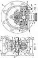
- a pair of plates 10 and 12 which have confronting cavity recesses 14 and 16 formed therein, are fastened together by bolts 18 (only one of which is shown). Fluid seals 20 and 22 are confined within the plates' parting line.
- the plates 10 and 12 have apertures 24 and 26 formed therein to accommodate the diaphragm-actuating rod 28 slidably therethrough.
- the bushing 30 is a through-bored block 38 which has an axial relief 40, in the outer surface thereof, along a length thereof.
- the block 38 has a threaded bore 48 formed therein, intermediate the length thereof, which opens onto the centre thereof.
- a machine screw 44 is threadably engaged with the bore 42, and the leading end of the shank of the screw is slidably disposed through the slot 36 and into the annular recess 34.
- a cylinder 46 closed at one end 48, has a slot 50 formed therein.
- annular-walled plug 52 At the end of the cylinder 46, opposite the closed end 48, is an annular-walled plug 52.
- the cylinder has a given, inside diameter, and the plug 52 has an inside diameter smaller than that of the cylinder 46.
- a piston 54 having two outside diameters, corresponding to the aforesaid inside diameters, is slidably disposed in the cylinder 46 and plug 52. Adjacent an end of the plug 52 there is a tapped hole 56 to receive a compressed air inlet fitting 60 ( Figure 6).
- the piston 54 has a first, axial bore 62 formed therethrough, the bore 62 having a first portion 64, and a second portion 66 which are out of axial alignment with each other.
- the portion 66 opens onto an end of the piston 54 and, internally, onto a second, transverse bore 68 formed fully through the piston 54.
- the portion 64 opens onto the opposite end of the piston 54, for communication with the tapped hole 56 and fitting 60, and, internally onto a third, transverse bore 70.
- the bores 68 and 70 are in open communication with each other.
- the cylinder 46 on opposite sides thereof, has apertures 72 and 74 formed therein. The latter are in alignment with the bore 70.
- Axially bored, round valves 76 and 78 are slidably disposed in the bore 70, and have 0-ring seals 80 fitted thereabout.
- the bore 68 has an intermediate portion 82 of a given inside diameter, a contiguous portion 84 of greater, inside diameter which opens onto the said slot 50, and another contiguous portion 86 with an outwardly widening termination which opens externally of the piston and opposite the portion 84.
- a button-headed valving element 88 is slidably disposed in the bore 68; its headed portion 90 having an 0-ring seal 92 thereabout, is in the portion 82 of bore 68.
- the element 88 further has a shank 94 with a pair of spaced-apart 0-ring seals 96 thereabout. Intermediate the seals 96, the shank 94 has an annular relief 98 formed therein.
- the cylinder 46 is set within the plates 10 and 12.
- Plates 10 and 12 have mating, semi-circular reliefs 100 and 102 formed therein in which to nest the opposite ends of the cylinder 46.
- the plates 10 and 12 have facing, longitudinal grooves 104 and 106 formed therein in which to receive a support panel 108.
- the panel 108 is slidably engaged with the grooves 104 and 106, and supports the cylinder 46 thereupon.
- the panel 108 has an aperture 110 formed therein which aligns with the tapped hole 56, and is commonly threaded therewith, to accommodate the fitting 60 therein.
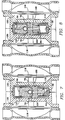
- the chambers 120 and 122 are put in communication with the exhaust chamber/cavity 112 via ports 124 and 126 formed in the plates 10 and 12.
- the ports 124 and 126 are not in alignment, however.
- round valve 78 covers port 126, but round valve 76 leaves port 124 open to the chamber/cavity 112.
- the air supply flows through the round valve 78, and port 126, and fills chamber 122.
- the diaphragm 118 is forced outwardly and pulls the rod 28 to the right (as viewed in Figure 1).
- the annular recess 34 engages the shank of the screw 44. This causes the block 38 to move to the right.
- the left end of the block 38 has no continuation of relief 40 therein, therefore the block cammingly depresses the headed portion 90 of the valving element 88.
- This opens the portion 66 of the bore 62 to the annular relief 98 of the valving element 88, and portion 86 of bore 68; therefore, air in the cylinder 46 which is in communication with portion 66 vents through to the chamber/cavity 112.
- the compressed air admitted via the fitting 60 forces the piston 54 to displace.
- the piston 54 moves from the disposition shown in Figure 7 to that shown in Figure 8. This connects the round valve 76 with port 124.
- the air enters chamber 120, causing the diaphragm 116 to deflect and reverse the travel of the rod 28.
- the present mechanism confines all of the pump-operating, air valving mechanism within the chamber 112 between the plates 10 and 12.
- the mechanism exhausts the motive air through no right-angular air passages and, as a consequence the formation of ice on the valving components is avoided.
- the mechanism has a minimum of parts and components, and these are modularly fitted together; this greatly enhances maintenance and repair as there is little need for disassembly tools.
- the round valves 76 and 78 effect air-tight seals against the plates 10 and 12. Consequently, manufacturing tolerances of the two plates need not be stringent; the valves close up against the plates to take up any tolerance deviation.
Landscapes
- Engineering & Computer Science (AREA)
- Mechanical Engineering (AREA)
- General Engineering & Computer Science (AREA)
- Reciprocating Pumps (AREA)
Applications Claiming Priority (2)
| Application Number | Priority Date | Filing Date | Title |
|---|---|---|---|
| US08/008,443 US5334003A (en) | 1993-01-25 | 1993-01-25 | Air valving mechanism, in combination with a double diaphragm pump subassembly |
| US8443 | 1993-01-25 |
Publications (1)
| Publication Number | Publication Date |
|---|---|
| EP0609044A1 true EP0609044A1 (de) | 1994-08-03 |
Family
ID=21731629
Family Applications (1)
| Application Number | Title | Priority Date | Filing Date |
|---|---|---|---|
| EP94300521A Ceased EP0609044A1 (de) | 1993-01-25 | 1994-01-25 | Luft-Ventilmechanismus in Kombination mit einer Doppel-Membranpumpe |
Country Status (4)
| Country | Link |
|---|---|
| US (1) | US5334003A (de) |
| EP (1) | EP0609044A1 (de) |
| JP (1) | JPH0735047A (de) |
| CA (1) | CA2113754A1 (de) |
Cited By (3)
| Publication number | Priority date | Publication date | Assignee | Title |
|---|---|---|---|---|
| EP0801228A3 (de) * | 1996-04-12 | 1999-07-21 | Graco Inc. | Doppelmembranpumpe |
| EP0942171A3 (de) * | 1996-04-12 | 2000-02-09 | Graco Inc. | Doppelmembranpumpe |
| US12618402B2 (en) | 2020-12-11 | 2026-05-05 | Leggett & Platt Canada Co. | Pump assembly |
Families Citing this family (11)
| Publication number | Priority date | Publication date | Assignee | Title |
|---|---|---|---|---|
| US5545016A (en) * | 1995-01-31 | 1996-08-13 | Standard-Keil Industries, Inc. | Plural chamber pneumatic pump having a motive fluid exhaust valve |
| US6901960B2 (en) * | 2002-09-06 | 2005-06-07 | Ingersoll-Rand Company | Double diaphragm pump including spool valve air motor |
| US6824364B2 (en) | 2002-09-20 | 2004-11-30 | Rimcraft Technologies, Inc. | Master/slave pump assembly employing diaphragm pump |
| US6865981B2 (en) * | 2003-03-11 | 2005-03-15 | Ingersoll-Rand Company | Method of producing a pump |
| US6883417B2 (en) * | 2003-03-19 | 2005-04-26 | Ingersoll-Rand Company | Connecting configuration for a diaphragm in a diaphragm pump |
| US20060219642A1 (en) * | 2005-04-04 | 2006-10-05 | Ingersoll-Rand Company | Control system and method for an air-operated pump |
| WO2010085744A2 (en) | 2009-01-23 | 2010-07-29 | Idex Aodd, Inc. | Method for increasing compressed air efficiency in a pump |
| CN102439308B (zh) * | 2009-05-08 | 2014-10-22 | 沃伦鲁普公司 | 具有发电机的气动隔膜泵 |
| US8382445B2 (en) * | 2009-12-16 | 2013-02-26 | Warren Rupp, Inc. | Air logic controller |
| US8932031B2 (en) | 2010-11-03 | 2015-01-13 | Xylem Ip Holdings Llc | Modular diaphragm pumping system |
| KR101449300B1 (ko) * | 2013-06-14 | 2014-10-08 | 양승빈 | 다이어프램 펌프 |
Citations (2)
| Publication number | Priority date | Publication date | Assignee | Title |
|---|---|---|---|---|
| US3791768A (en) * | 1972-06-16 | 1974-02-12 | W Wanner | Fluid pump |
| US4019838A (en) * | 1975-09-03 | 1977-04-26 | Fluck Henry T | Air pressure-actuated double-acting diaphragm pump with means to produce a selected start-up position |
Family Cites Families (9)
| Publication number | Priority date | Publication date | Assignee | Title |
|---|---|---|---|---|
| US2307566A (en) * | 1940-07-31 | 1943-01-05 | Wright Aeronautical Corp | Pneumatic drive fuel pump |
| US3652187A (en) * | 1970-10-29 | 1972-03-28 | Amicon Corp | Pump |
| US3782863A (en) * | 1971-11-16 | 1974-01-01 | Rupp Co Warren | Slide valve apparatus |
| DE2726667A1 (de) * | 1977-06-14 | 1978-12-21 | Licentia Gmbh | Oberflaechenpassiviertes halbleiterbauelement und verfahren zum herstellen desselben |
| DE3112434A1 (de) * | 1981-03-28 | 1982-10-07 | Depa GmbH, 4000 Düsseldorf | Druckluftgetriebene doppelmembran-pumpe |
| DE3113787C2 (de) * | 1981-04-04 | 1985-08-22 | Friedrich Wilh. Schwing Gmbh, 4690 Herne | Rohrweiche für Beton- oder Dickstoffkolbenpumpen |
| CA1172904A (en) * | 1981-10-23 | 1984-08-21 | Savage (D.B.) Industrial Sales Limited | Fluid driven reciprocating pump |
| JPS6295186U (de) * | 1985-12-06 | 1987-06-17 | ||
| DE3940629A1 (de) * | 1989-12-08 | 1991-06-13 | Tomas Sirek | Durch gasfoermigen medien angetriebene membran oder kolbenpumpe, mit integriertem druckminderventil |
-
1993
- 1993-01-25 US US08/008,443 patent/US5334003A/en not_active Expired - Lifetime
-
1994
- 1994-01-19 CA CA002113754A patent/CA2113754A1/en not_active Abandoned
- 1994-01-25 EP EP94300521A patent/EP0609044A1/de not_active Ceased
- 1994-01-25 JP JP6006264A patent/JPH0735047A/ja active Pending
Patent Citations (2)
| Publication number | Priority date | Publication date | Assignee | Title |
|---|---|---|---|---|
| US3791768A (en) * | 1972-06-16 | 1974-02-12 | W Wanner | Fluid pump |
| US4019838A (en) * | 1975-09-03 | 1977-04-26 | Fluck Henry T | Air pressure-actuated double-acting diaphragm pump with means to produce a selected start-up position |
Cited By (3)
| Publication number | Priority date | Publication date | Assignee | Title |
|---|---|---|---|---|
| EP0801228A3 (de) * | 1996-04-12 | 1999-07-21 | Graco Inc. | Doppelmembranpumpe |
| EP0942171A3 (de) * | 1996-04-12 | 2000-02-09 | Graco Inc. | Doppelmembranpumpe |
| US12618402B2 (en) | 2020-12-11 | 2026-05-05 | Leggett & Platt Canada Co. | Pump assembly |
Also Published As
| Publication number | Publication date |
|---|---|
| US5334003A (en) | 1994-08-02 |
| JPH0735047A (ja) | 1995-02-03 |
| CA2113754A1 (en) | 1994-07-26 |
Similar Documents
| Publication | Publication Date | Title |
|---|---|---|
| EP0609044A1 (de) | Luft-Ventilmechanismus in Kombination mit einer Doppel-Membranpumpe | |
| KR0158761B1 (ko) | 유압 실린더 | |
| US5173036A (en) | Method and an arrangement for controlling a linear motor | |
| US5607290A (en) | Air driven diaphragm pump | |
| US6082243A (en) | Fluid controlled switching unit | |
| CN109611305B (zh) | 一种增压水泵 | |
| US6499974B2 (en) | Piston pump | |
| US4870891A (en) | Pneumatically controlled air motor | |
| KR200228106Y1 (ko) | 유압 실린더의 씰링 장착 구조 | |
| JP2001050406A (ja) | マルチウェイバルブ | |
| JPH06298072A (ja) | マスタシリンダ | |
| EP1775468A2 (de) | Ventileinrichtung | |
| KR20090029714A (ko) | 유압식 펌프 | |
| CN114165621B (zh) | 一种活塞式换向阀 | |
| US2988010A (en) | Pump | |
| KR200181790Y1 (ko) | 자동차의 변속기 조작용 배력장치의 실린더 구조 | |
| JP2605521Y2 (ja) | ダイヤフラムポンプ | |
| CN112673202A (zh) | 滑阀 | |
| US11859607B2 (en) | Fully actuated valve for a reciprocating machine and reciprocating machine including said valve | |
| EP0786583A2 (de) | Drehventil- und Wegventil-Kombination | |
| JPS6316851Y2 (de) | ||
| EP0371176A1 (de) | Hydraulische mehrstufige Gleichlaufpumpe | |
| WO2000040864A2 (en) | Pump | |
| US4443162A (en) | Fluid pump | |
| KR20030030276A (ko) | 콘트롤 밸브에 의한 공압실린더 제어방법 및 공압실린더용콘트롤 밸브 |
Legal Events
| Date | Code | Title | Description |
|---|---|---|---|
| PUAI | Public reference made under article 153(3) epc to a published international application that has entered the european phase |
Free format text: ORIGINAL CODE: 0009012 |
|
| AK | Designated contracting states |
Kind code of ref document: A1 Designated state(s): BE DE ES FR GB IT NL SE |
|
| 17P | Request for examination filed |
Effective date: 19950128 |
|
| 17Q | First examination report despatched |
Effective date: 19960112 |
|
| GRAG | Despatch of communication of intention to grant |
Free format text: ORIGINAL CODE: EPIDOS AGRA |
|
| STAA | Information on the status of an ep patent application or granted ep patent |
Free format text: STATUS: THE APPLICATION HAS BEEN REFUSED |
|
| 18R | Application refused |
Effective date: 19961221 |