EP0609049B2 - Dispositif de retenue pour camion - Google Patents
Dispositif de retenue pour camion Download PDFInfo
- Publication number
- EP0609049B2 EP0609049B2 EP94300536A EP94300536A EP0609049B2 EP 0609049 B2 EP0609049 B2 EP 0609049B2 EP 94300536 A EP94300536 A EP 94300536A EP 94300536 A EP94300536 A EP 94300536A EP 0609049 B2 EP0609049 B2 EP 0609049B2
- Authority
- EP
- European Patent Office
- Prior art keywords
- locking arm
- lock assembly
- base
- wheel
- loading dock
- Prior art date
- Legal status (The legal status is an assumption and is not a legal conclusion. Google has not performed a legal analysis and makes no representation as to the accuracy of the status listed.)
- Expired - Lifetime
Links
- 230000000452 restraining effect Effects 0.000 title claims description 70
- 238000000034 method Methods 0.000 claims description 13
- 230000000694 effects Effects 0.000 claims 1
- 238000003860 storage Methods 0.000 description 10
- 230000007246 mechanism Effects 0.000 description 4
- 238000012986 modification Methods 0.000 description 3
- 230000004048 modification Effects 0.000 description 3
- 238000004513 sizing Methods 0.000 description 3
- 230000001360 synchronised effect Effects 0.000 description 3
- 230000000284 resting effect Effects 0.000 description 2
- 229910000831 Steel Inorganic materials 0.000 description 1
- 230000000712 assembly Effects 0.000 description 1
- 238000000429 assembly Methods 0.000 description 1
- 230000004888 barrier function Effects 0.000 description 1
- 231100001261 hazardous Toxicity 0.000 description 1
- 230000002452 interceptive effect Effects 0.000 description 1
- 238000004519 manufacturing process Methods 0.000 description 1
- 239000002994 raw material Substances 0.000 description 1
- 239000010959 steel Substances 0.000 description 1
- 230000032258 transport Effects 0.000 description 1
Images


Classifications
-
- B—PERFORMING OPERATIONS; TRANSPORTING
- B65—CONVEYING; PACKING; STORING; HANDLING THIN OR FILAMENTARY MATERIAL
- B65G—TRANSPORT OR STORAGE DEVICES, e.g. CONVEYORS FOR LOADING OR TIPPING, SHOP CONVEYOR SYSTEMS OR PNEUMATIC TUBE CONVEYORS
- B65G69/00—Auxiliary measures taken, or devices used, in connection with loading or unloading
- B65G69/003—Restraining movement of a vehicle at a loading station using means not being part of the vehicle
- B65G69/005—Restraining movement of a vehicle at a loading station using means not being part of the vehicle the means engaging at least one wheel of the vehicle
Definitions
- the present invention relates to a device for restraining a vehicle from movement from the parked position during the loading and unloading operation at a loading dock.
- FR-A-2652340 discloses a device for restraining a vehicle from movement during loading and unloading of the vehicle, with the vehicle having at least one wheel supported on a driveway adjacent a loading dock.
- the device includes a lock assembly having two members movable relative to each other between an inoperative position and an operative position.
- the lock assembly can be located between the distal and proximal locations relative to the loading dock and is movable to an engaging position wherein the lock assembly in the operative position engages the wheel to prevent movement of the vehicle.
- a further object of the invention is to provide a device which is compact and has a low profile for accommodating vehicles having low undercarriages.
- Another object of the invention is to provide a device which may be readily installed in existing loading docks without extensive structural modifications.
- a similar object of the invention is to provide a device which may be readily utilized in conjunction with other loading dock equipment such as dock levellers and the like without interfering with the operation of the loading dock
- a further object of the invention is to provide a device which is not hazardous to either personnel or the vehicle.
- Still another object of the invention is to provide a device which may be remotely operated and controlled and which may be effectively secured against unauthorized use.
- a device for restraining a vehicle from movement during the loading and unloading thereof as defined in claim 1.
- a method for restraining a vehicle from movement away from a loading dock during the loading and unloading thereof using a restraining device as defined in claim 13.
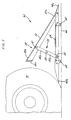
- FIG. 1 one embodiment of the vehicle restraining device 10 in accordance with the invention is shown installed on a conventional loading dock roadway R normally provided at warehouses, truck terminals, manufacturing plants and the like where raw materials and products are received and/or dispatched by truck vehicles.
- a conventional loading dock roadway R normally provided at warehouses, truck terminals, manufacturing plants and the like where raw materials and products are received and/or dispatched by truck vehicles.
- the conventional loading dock D is normally provided with a horizontal surface or deck S over which loading equipment such as forklift trucks and the like and dock personnel maneuver during the loading and unloading operation.
- the dock D is typically provided with a leveler assembly L which is adapted to compensate for height differentials between the deck S and the upper supporting surface of the truck bed (not shown).
- the mechanism (not shown) for effecting adjustment of the leveler assembly L is customarily disposed within a pit formed in the deck S of the dock D and is well known in the art.
- the dock D normally includes a vertical wall V or surface against which the rear end of the truck abuts during the loading and unloading operations.
- the surface V is provided with suitable bumpers B or fenders which are engaged by the rear of the vehicle thereby preventing damage or defacement of either the dock D or the vehicle when the vehicle is backing into position.
- the vehicle restraining device 10 is intended to effectively and readily secure the truck in proper position relative to the dock D and prevent the truck from inadvertently moving away from the dock D during the loading and unloading operation.
- the vehicle restraining device 10 comprises restraining means 12 for engaging at least one of the truck wheels W (FIG. 2) and for securing the truck from movement, positioning means 14 for positioning the restraining means 12 between distal and proximal positions relative to the dock wall V and an intermediate position between the distal and proximal positions for engaging the wheels W after the truck is parked adjacent the loading dock D, and controlling means for determining the position of the restraining means 12 between the distal and proximal positions and positioning the restraining means 12 in a programmed manner.
- the vehicle restraining device 10 is generally disposed in the center of the driveway R adjacent the loading dock D so that the truck may drive over the restraining device 10 during the parking operation.
- the restraining device 10 has a generally T-shape formed by the positioning means 14, and the restraining means 12 projecting laterally from the positioning means 14 for selectively engaging each set of rear wheels W on each side of the truck.
- the positioning means 14 comprises a carriage assembly 16 adapted for slidably receiving the restraining means 12 for movement between the proximal and distal ends 18, 20 of the carriage assembly 16 and means for moving the restraining means 12 along the carriage assembly 16.
- the carriage assembly 16 is fixedly disposed on the driveway so that its longitudinal axis is generally perpendicular to the dock wall V and it will be generally parallel to the longitudinal axis of the truck when the rear of the truck is adjacent the loading dock D. In a preferred embodiment illustrated in FIGS.
- the carriage assembly 16 has a base 22 which is adapted to slidably receive the restraining means 12 and a channel 24 disposed along the length of the base 22 for housing a lead screw 26 for driving the restraining means 12 as described below.
- the carriage assembly 16 may be fixedly attached to the driveway in any conventional manner.
- a plurality of bolts 28 fixedly attach the base 22 to the surface of the driveway so that the channel 24 is above grade.
- the positioning means comprises a channel 124 formed below the driveway grade and adapted to receive the lead screw 26 therein.
- the means for moving the restraining means 12 between the distal and proximal ends 18, 20 of the carriage assembly 16 comprises a synchronous motor 30 operatively attached by a flexible drive cable 32 to the lead screw 26.
- a lead nut 34 threadedly attached to the lead screw 26 and a cam follower 36 are linearly positioned along the length of the lead screw 26.
- the motor 30 is disposed at the base of the loading dock D but it may be located in any convenient location. Although a synchronous motor 30 and lead screw 26 are preferred, it will be appreciated that the positioning means 14 may comprise other types of actuators such as, for example hydraulic or pneumatic actuators, a chain drive or other types of electromechanical actuating mechanisms which are known in the art.
- the restraining means 12 may only have one lock assembly 42 for selectively engaging one of the wheels W on either side of the truck T, in the illustrated embodiment, the restraining means 12 comprises a pair of lock assemblies 42 which are fixedly attached to the cover means 40 and spaced on either side of the carriage assembly 16 for selectively engaging the respective wheels W on either side of the truck.
- the cover means 40 has a top plate 40a and two depending sides 40b which slidably enclose the base 22 of the carriage assembly 16 (in the preferred embodiment in FIGS. 1 and 7-9).
- a slot 40c is disposed in the top plate 40a.
- the cover means 40 may be desirable to have a plurality of wheels 46 rotatably attached to the sides of the cover means 40 in order to support the cover means 40 above the surface of the driveway 16 and to assist the movement of the cover means 40 along the length of the channel 24. Since the longitudinal axis of the carriage assembly 16 is generally parallel with the axis of the parked truck, the cover means 40 and the attached lock assembly 42 may be positioned along the axis of the truck so that the lock assembly 42 may engage the truck wheels W.
- the lock assembly 42 comprises a base 48 rigidly attached to the cover means 40 by arms 49, a locking arm 50 pivotally attached to the base 48 for rotating between a retracted storage position shown in FIG. 2, an intermediate preparatory position shown in FIG. 3, and an extended restraining position shown in FIG. 4. and rotating means for rotating the locking arm 50 between the retracted and extended positions.
- the lock assembly 42 has a relatively low, horizontal profile in the retracted position (FIG. 2) which permits trucks having low undercarriages to pass over the restraining means 12 during the parking operation.
- the base 48 has a front edge 48a and a rear edge 48b which are generally wedge-shaped to permit the truck to readily drive thereover when the lock assembly 42 is in the retracted position (FIG. 2).
- the lock assembly may also act as a speed bump to slow the truck parking in the loading dock area.
- the locking arm 50 projects upwardly in order to create a barrier preventing the truck from inadvertently driving forward during the loading and unloading operation.
- the lock assembly can restrain trucks with or without an ICC bumper.
- the wedge shape permits the rear edge 48b of the base 48 to wedge underneath the wheel W when the lock assembly 42 is in the extended position (FIG. 4). Referring to FIG. 3, it will be seen that the rear edge 48b of the base 48 extends past the rearmost position of the rear end 50b of the locking arm 50 so that the truck wheel W will not interfere with the rotation of the locking arm 50 between the retracted and the extended positions.
- the locking arm 50 comprises a plate 52 having a front end 50a pivotally attached to the front edge 48a of the base 48 at pin 53.
- the rear end 50b of the locking arm 50 is free to rotate from the retracted position to the extended position for directly engaging the wheel W.
- the rear end 50b of the locking arm 50 preferably has a relatively flat or slightly curved face 50c adapted to engage the face of the truck wheel W.
- the rotating means comprises a crank 54 operatively connected to the locking arm 50 by crank drive shafts 55 and link means 56 best shown in FIGS. 1 and 5-6.
- the crank drive shaft 55 has one end 55a rigidly attached to the crank 54 and a second end 55b operatively attached to the rear end 50b of the looking arm 50 by link means 56.
- the link means 56 comprises a first link 56a rigidly attached to the drive shaft 55 and rotatably attached to a second link 56b at pin 60.
- the second link 56b is pivotally attached to the rear end 50b of the locking arm 50 at pin 61.
- crank 54 is movable between a retracted position shown in solid lines and an extended position shown in phantom lines.
- the crank drive shaft 55 and the link means 56 rotate the locking arm 50 from the retracted position (FIG. 2) to the extended restraining position (FIG. 4).
- the crank 54 In order to rotate the crank 54 between the retracted and the extended positions, the crank 54 is operatively connected to the positioning means 14.
- the drive link 62 operatively connects the crank 54 and the positioning means 14 and is able to push or pull the lock assembly 42 between the proximate and distal positions 18, 20.
- the drive link 62 passes through the slot 40c in the cover means so that first end 62a of the drive link 62 is generally disposed above the cover means 40 for pivotally connecting to the crank 54 at pin 64 and the second end 62b is generally disposed inside the channel 24 of the carriage assembly 16 for pivotally attaching to the lead nut 34 and cam follower 36 at pin 35.
- the drive link 62 After the drive link 62 pulls the lock assembly 42 into engagement with the truck wheel W, the drive link 62 continues pulling so that the drive link 62 rotates in the counterclockwise direction and the crank 54 rotates the locking arm 50 from the retracted position (FIG. 2)into the extended position (FIGS. 3, 4).
- the drive link 62 pushes the lock assembly 42 away from the truck wheel W, the drive link 62 initially pushes the crank 54 in the clockwise direction, rotating the locking arm 50 from the extended position (FIGS. 3, 4) to the retracted position (FIG. 2).
- the drive link 62 operatively connects the restraining means 12 and the positioning means 14, the restraining means 12 may be positioned between the proximal and distal ends 18, 20 of the carriage assembly 16 as discussed above.
- the lock assembly 42 may have sizing means for automatically accommodating different size wheels.
- the sizing means comprises a plurality of base wheels 66 pivotally mounted to the base 48 for rotating between an active position and a collapsed position. In the active position, the wheels 66 support the base 48 of the lock assembly 48 above the driveway as shown in FIGS. 2-3 when the locking assembly 42 is moving between the distal and proximal positions 18,20. In the collapsed position, the base 48 of the lock assembly rests upon the driveway as shown in FIG. 4. Referring to FIG. 5, there is shown a pair of front and rear wheels 66a.
- the positioning means 14 forces the rear edge 48b of the base 48 into engagement with the truck wheels W so that the force exerted on the lock assembly 42 by the positioning means 14 overcomes the spring force, the base wheels 66 rotate towards the collapsed position and the base 48 is lowered toward the driveway until the face 50c of the locking arm 50 engages the face of the wheel. For large wheels, the face 50c will typically engage the wheel before the base 48 engaged the driveway.
- the base 48 will collapse so that it rests on the driveway and rear edge 48b of the base 48 wedge underneath the wheel W, as shown in FIG. 4.
- the spring force is sufficient to extend to base wheels 66 so that the base 48 is raised to its highest position above the ground.
- the truck In operation, the truck is parked in the loading dock D in the conventional manner so that the rear edge of the truck abuts the bumpers B.
- the lock assembly 42 is typically stored at the distal position 20 of the carriage assembly 16 in the retracted position. It will be appreciated that the low profile of the restraining device 10 will not interfere with the parking operation and the truck may readily drive over the wedge-shaped lock assembly 42.
- the operator activates the positioning means 14 which moves the lock assembly 42 from the distal end 20 of the carriage assembly 16 to the intermediate position wherein the lock assembly 42 engages the truck wheel W.
- the motor 30 rotatably drives the flexible cable 32 and lead screw 26 which linearly positions the lead nut 34 and cam follower 36 within the channel 24.
- the lead screw 26 pulls the drive link 62 operatively connecting the lead screw 26 and the locking assembly 42.
- the base wheels 66 support the locking assembly 42 above the driveway from the distal end 20 of the carriage assembly 16 to the intermediate position wherein the rear end 48b of the base 48 initially engages the truck wheel W as shown in FIG. 3.
- the lead screw 26 continues pulling the drive link 62 thereby rotating the crank 54 in the counterclockwise direction.
- the counterclockwise rotation of the crank 54 rotates the crank drive shaft 55 and the link means 56, thereby rotating the locking arm 50 from the retracted position shown in FIG. 2 to the extended position in FIGS. 3-4.
- the rear end 48b of the base 48 extends past the rearmost position of the locking arm 50 so that the locking arm 50 may rotate upwardly without engaging the truck wheel W.
- the base 48 of the lock assembly 42 is supported above the driveway and the rear edge 48b engages the truck wheel W so that the face 50c of the locking arm 50 cannot yet engage the truck wheel W.
- the sizing means permits the lock assembly 42 to adjust its position to automatically accommodate different size truck wheels W.
- the positioning means 14 continues pulling the lock assembly 42 into engagement with the truck wheel W until the force is sufficient to overcome the force of the spring 68, thereby collapsing the base wheels 66.
- the base 48 descends toward the driveway permitting the lead screw 26 to continue pulling the face 50c of the lock assembly 42 into secure engagement with the truck wheel W.
- the face 50c of the locking arm 50 will securely engage the wheel W thereby preventing the truck from movement during the loading/unloading operation.
- the positioning means 14 is automatically deactivated.
- the dock operator activates the motor 30 which rotates the flexible cable 32, the lead screw 26 and forces the lead nut 34 towards the distal end 20 of the carriage assembly 16.
- the lock assembly 42 securely engages the truck wheel W so that the locking arm 50 cannot rotate from the extended position to the retracted position. Therefore, the motor continues driving the lock assembly 42 towards the distal end 20 until the locking arm 50 disengages the wheel W.
- the drive link 62 rotates the crank 54 in the clockwise direction from the extended position, thereby closing the lock assembly 42.
- the spring 68 rotates the base wheels 66 into the active position which raises the base 48 above the driveway so that the lock assembly 42 may readily be positioned to the distal end 20 of the carriage assembly 16 for the next vehicle.
- the truck In the retracted position, the truck may drive over the restraining means 12 and depart from the loading dock.
- Controlling means is provided for determining the position of the restraining means 12 between the distal and proximal ends 18, 20 of the carriage assembly 16 and the position of the lock assembly 42 between the retracted and extended positions and then for positioning the restraining means 42 in a programmed manner.
- the controlling means determines whether the position of the restraining means 12 is at the proximal or distal ends 18, 20 of the carriage assembly 16 and whether the restraining means 12 is stationary and whether the locking arm 50 is retracted or extended.
- the restraining means 12 be positioned at the distal end 20 of the carriage assembly 16 when the restraining device 10 is not actively being utilized, so that the restraining means 12 may be positioned from the distal end 20 towards the proximal end 18 to engage the truck wheels W somewhere therebetween.
- the restraining means 12 be stored at the proximal end 18 of the carriage assembly 16 in the storage position because, once the truck is parked in the loading dock D, the lock assembly 42 can not be positioned to the front of the truck wheels W without removing the truck from the loading dock D.
- the carriage assembly 16 has distal end indicator means (not shown) for indicating when the restraining means 12 is at the distal end 20 and proximal end indicator means (not shown) for indicating when the restraining means 12 is at the proximal end 18 of the carriage assembly 16.
- the indicator means may be connected to the controlling means in any conventional manner including, for example, a continuous switch or wire means located in the carriage assembly 16.
- the controlling means will deactivate the motor 30 when the distal end indicator means indicates that the restraining means 12 is positioned at the distal end 20 in the normal storage mode.
- the controlling means will automatically return the restraining means 12 to the storage position at the distal end 20 of the carriage assembly 16 for the next incoming vehicle.
- the controlling means may activate an alarm indicating that the restraining device 12 can not properly restrain the truck from movement.
- the restraining means 12 will typically be stationary when it engages a truck wheel W or other immovable obstacle or when an object is resting on the restraining means 12.
- the controlling means monitors the synchronous motor 30 which will indicate that the restraining means 12 is stationary when the motor torque or current increases to a predetermined value. If the dock personnel activates the restraining device 10 but the restraining means 12 can not move because, for example, the truck wheel is sitting on the restraining means 12, the controlling means will automatically deactivate the motor 30 and sound an alarm.
- a position sensor means (not shown) may be mounted to the restraining means 12.
- the position sensor means may be mounted to the crank 54, the drive link 62, or the locking arm 50 to indicate when the respective member is positioned between the retracted or the extended positions.
- the controlling means may sound an alarm indicating that the truck may not attempt to drive over the restraining means 12.
- the controlling means may sound an alarm if the locking arm 50 is in the extended position at the distal end 20 of the carriage assembly 16 indicating that the truck should not enter the loading dock D.
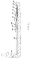
- Figs. 10-11 illustrate another embodiment of the restraining device in which the lock assembly 142 is stored below driveway grade instead of above grade as shown in Figs. 1-9.
- the positioning means comprises a channel 124 disposed below grade and adapted to receive the lead screw therein.
- a storage chamber 100 for storing the lock assembly 142 below grade is disposed at the distal end 20 of the driveway.
- the storage chamber 100 has a ramp 102 permitting the lock assembly 142 to travel between the driveway and the storage chamber 100, a steel cover 104 and trap door 106 for covering the storage chamber 100.
- the lock assembly 142 operates as described above although it will be appreciated that the drive link 162 will have to be long enough to connect the crank 154 and the lead screw 126 after the lock assembly 142 is above grade as illustrated in Fig. 10.
- Fig. 11 also illustrates the motor 130 remotely located from the channel 124 and lead screw 126.
- the positioning means including the drive link 162 and the crank 154 pulls the lock assembly 142 resting in the storage compartment rearwardly so that the lock assembly 142 travels up the ramp 102 and pivots the trap door 106 open about pivot pin 108.
- the positioning means transports the lock assembly towards the distal position 20 and the storage chamber 100.
- the trap door 106 can be opened either by dock personnel or by other conventional means known in the art.
Landscapes
- Engineering & Computer Science (AREA)
- Mechanical Engineering (AREA)
- Loading Or Unloading Of Vehicles (AREA)
- Auxiliary Methods And Devices For Loading And Unloading (AREA)
- Vehicle Step Arrangements And Article Storage (AREA)
Claims (19)
- Dispositif destiné à retenir un véhicule afin qu'il ne se déplace pendant son chargement et son déchargement, le véhicule possédant au moins une roue (w) supportée sur un passage adjacent à un quai de chargement, le dispositif comprenant un ensemble (12) de blocage possédant deux organes (48, 50) mobiles l'un par rapport à l'autre, entre une position de repos et une position de travail, et un dispositif (14) de localisation de l'ensemble de blocage (12) entre des emplacements éloigné et rapproché par rapport au quai de chargement (D) et à déplacer l'ensemble de blocage (12) vers une position de coopération dans laquelle l'ensemble de blocage (12) en position de travail est au contact de la roue (W) pour empêcher le déplacement du véhicule, caractérisé en ce que les organes forment une base (48) et un bras de blocage (50), la base (48) étant disposée et maintenue en direction pratiquement parallèle au passage, et le bras de blocage (50) ayant une partie arrière (50c) et une partie avant (50a) qui est montée de manière pivotante sur la base, si bien que le bras de blocage (50) peut pivoter vers le haut par rapport à la base (48) vers une position de travail totalement allongée dans laquelle l'extrémité libre du bras de blocage (50) est disposée au-dessus de la base (48) et la partie arrière (50c) est soulevée, la partie arrière (50c) étant plus proche du quai de chargement (D) que la partie avant (50a) à la fois dans les positions de travail et de repos de l'ensemble (12) de blocage, un dispositif (54) de positionnement est destiné à positionner le bras de blocage (50) entre une position reculée de repos permettant au véhicule d'être conduit au quai de chargement et une position totalement allongée, et le dispositif (14) de localisation de l'ensemble de blocage est destiné à déplacer l'ensemble de blocage (12) vers un emplacement intermédiaire compris entre les emplacements éloigné et rapproché et dans lequel la base (48) détecte la roue (W), et en outre à déplacer l'ensemble de blocage (12) avec le bras de blocage (50) en position reculée depuis l'emplacement éloigné vers l'emplacement intermédiaire, le dispositif de positionnement (54) est destiné à faire pivoter le bras de blocage vers la position totalement avancée à la suite de la détection de la roue, et le dispositif de localisation (14) est destiné à déplacer ensuite le bras de blocage (50) en position totalement allongée avec la base au contact de la roue, si bien que la partie arrière (50c) du bras de blocage (50) coopère avec la roue (W), afin que le déplacement du véhicule près du quai de chargement soit limité.
- Dispositif selon la revendication 1, dans lequel le dispositif de positionnement (54) est associé pendant le fonctionnement au dispositif de localisation (14) afin que le dispositif de positionnement (54) soit commandé en fonction du dispositif de localisation.
- Dispositif selon la revendication 1, dans lequel le bras de blocage (50) est associé pendant le fonctionnement au dispositif de localisation (14) afin que le bras de blocage (50) soit positionné entre les positions reculée et de travail.
- Dispositif selon la revendication 3, dans lequel un levier coudé (54) raccorde pendant le fonctionnement le bras de blocage (50) et le dispositif de localisation (14) afin qu'il fasse tourner le bras de blocage (50) entre les positions reculée et de travail.
- Dispositif selon la revendication 4, comprenant un arbre menant (55) ayant une première extrémité raccordée rigidement au levier coudé (54) et une seconde extrémité fixée rigidement au dispositif de liaison (56), et le dispositif de liaison (56) étant fixé de manière pivotante au bras de blocage (50) afin que le bras de blocage (50) tourne lors de la rotation du levier coudé commandé par le dispositif de localisation (14).
- Dispositif selon la revendication 1, dans lequel le bras de blocage (50) est plan de façon générale et pivote autour d'un axe parallèle de façon générale à une paroi verticale de façon générale du quai de chargement (D) lorsque le bras (50) est dans les positions reculée et de travail.
- Dispositif selon la revendication 1, dans lequel une partie à organe de manoeuvre (48B) de l'ensemble de blocage (12) coopère pendant le fonctionnement avec la roue (W) au cours du déplacement de l'ensemble de blocage (12) vers la position intermédiaire, la partie à organe de manoeuvre (48B) étant associée pendant le fonctionnement au bras de blocage (50) pour assurer le déplacement du bras de blocage (50) vers la position de travail.
- Dispositif selon la revendication 1, dans lequel le dispositif de localisation (14) comprend une vis-mère (26) montée entre les positions éloignée et rapprochée, et un dispositif (30, 32) destiné à entraíner en rotation la vis-mère (26), l'ensemble de blocage (12) étant raccordé pendant le fonctionnement à la vis-mère (26) afin qu'il se déplace le long de la vis-mère (26) lors de la rotation de la vis-mère (26).
- Dispositif selon la revendication 8, dans lequel le dispositif de positionnement (14) comprend un canal (124) de logement de la vis-mère (26).
- Dispositif selon la revendication 8, dans lequel la vis-mère (26) est logée dans un canal (124) au-dessous de la rampe du passage du quai de chargement.
- Dispositif selon la revendication 8, dans lequel le dispositif d'entraínement comprend un moteur (30) raccordé pendant le fonctionnement à la vis-mère (26) afin qu'il fasse tourner la vis-mère (26).
- Dispositif selon la revendication 1, dans lequel l'ensemble de blocage (12) comporte un dispositif d'ajustement de la position du bras de blocage (50) pour le logement de dispositifs à roue (W) de dimensions différentes, comprenant un dispositif (66) de déplacement de la base (48) entre une position active dans laquelle l'ensemble de blocage (12) est supporté au-dessus du passage et une position affaissée dans laquelle la base (48) est au contact du passage, le dispositif de déplacement (66) étant destiné à se déplacer de la position active à une position comprise entre la position active et la position pliée dans laquelle le bras de blocage (50) est au contact de la roue (W) de camion.
- Procédé de retenue d'un véhicule afin qu'il ne s'écarte pas d'un quai de chargement pendant le chargement et le déchargement de celui-ci, à l'aide d'un dispositif de retenue, le véhicule étant supporté par des roues sur un passage adjacent à un quai de chargement ayant une partie de mur vertical, le procédé comprenant le montage du dispositif de retenue avec un ensemble de blocage (12) possédant deux organes (48, 50) mobiles l'un par rapport à l'autre en une position reculée destinée à permettre au camion d'être conduit au quai de chargement et une position allongée, le montage d'un dispositif (14) de localisation de l'ensemble de blocage entre les positions éloignée et rapprochée par rapport au quai de chargement et à déplacer l'ensemble de blocage (12) vers une position de coopération comprise entre les positions éloignée et rapprochée par rapport au quai de chargement (D) et à déplacer l'ensemble de blocage (50) vers une position de coopération dans laquelle l'ensemble de blocage (12) en position allongée est au contact de la roue (W) pour empêcher le déplacement du véhicule, et de mise en stationnement du véhicule près du quai de chargement afin que l'axe longitudinal du camion soit perpendiculaire de leçon générale au mur muni de l'ensemble de blocage (12) en position éloignée, le procédé étant caractérisé par la formation de l'organe à l'aide d'une base (48) et d'un bras de blocage (50), la disposition et le maintien de la base en position sensiblement parallèle au passage, le bras (50) ayant une partie arrière (50c) et une partie avant (50a) qui est montée de manière pivotante sur la base (48) afin que le bras (50) puisse pivoter vers le haut par rapport à la base (48) vers une position totalement allongée dans laquelle l'extrémité libre du bras de blocage (50) est disposée au-dessus de la base (48), et dans laquelle la partie arrière (50c) est soulevée, la partie arrière (50c) étant plus proche du quai de chargement (D) que la partie avant (50a) à la fois dans les positions de travail et de repos de l'ensemble (12) de blocage, le déplacement de l'ensemble de blocage (12) vers une position intermédiaire comprima entre les emplacements éloigné et rapproché, dans lequel la base (48) détecte la roue, avec le bras de blocage (50) en position reculée, le positionnement du bras de blocage (50) de la position reculée à la position de travail à la suite de la détection de la roue par pivotement du bras de blocage (50) par rapport à la base (48), si bien que le bras de blocage (50) est totalement allongé par rapport à la base (48), puis le déplacement du bras allongé de blocage (50) avec la base (48) au contact de la roue, si bien que la partie arrière (50c) du bras de blocage (50) coopère avec la roue, afin que le déplacement du véhicule près du quai de chargement soit limité.
- Procédé selon la revendication 13, dans lequel l'ensemble de blocage (12) comporte un dispositif d'ajustement de la position du bras de blocage (50) pour le logement de dispositifs à roue (W) de dimensions différentes, comprenant un dispositif de déplacement de la base (48) entre une position active dans laquelle l'ensemble de blocage (12) est supporté au-dessus du passage et une position pliée dans laquelle la base (48) est au contact du passage, le procédé comprenant le positionnement du dispositif (66) de déplacement de la position active à une position comprise entre les positions active et pliée après que le bras de blocage (50) a été mis en position allongée, si bien que le bras de blocage (50) est au contact de la roue (W).
- Procédé selon la revendication 13, comprenant la localisation automatique de l'ensemble de blocage (12) à la position éloignée après que le bras de blocage (50) a été déplacé de la position de travail à la position reculée.
- Procédé selon la revendication 13, comprenant la localisation automatique de l'ensemble de blocage (12) en position éloignée lorsque l'ensemble de blocage (12) atteint la position rapprochée.
- Procédé selon la revendication 13, comprenant la désactivation automatique du dispositif de localisation (14) lorsque l'ensemble de blocage (12) est immobile.
- Procédé selon la revendication 17, comprenant la désactivation automatique du dispositif de localisation (14) après qu'une force de traction appliquée à l'ensemble de blocage (12) a atteint une valeur prédéterminée.
- Procédé selon la revendication 17, dans lequel le dispositif de localisation (14) comporte un moteur (30), le procédé comprenant la désactivation automatique du dispositif de localisation (14) après que le courant ou le couple du moteur (30) a atteint une valeur prédéterminée.
Priority Applications (1)
| Application Number | Priority Date | Filing Date | Title |
|---|---|---|---|
| EP98203811A EP0911285B1 (fr) | 1993-01-25 | 1994-01-25 | Dispositif de retenue pour camion |
Applications Claiming Priority (2)
| Application Number | Priority Date | Filing Date | Title |
|---|---|---|---|
| US08008757 US5375965C1 (en) | 1993-01-25 | 1993-01-25 | Vehicle restraining device |
| US8757 | 1998-01-19 |
Related Child Applications (1)
| Application Number | Title | Priority Date | Filing Date |
|---|---|---|---|
| EP98203811A Division EP0911285B1 (fr) | 1993-01-25 | 1994-01-25 | Dispositif de retenue pour camion |
Publications (3)
| Publication Number | Publication Date |
|---|---|
| EP0609049A1 EP0609049A1 (fr) | 1994-08-03 |
| EP0609049B1 EP0609049B1 (fr) | 1999-07-21 |
| EP0609049B2 true EP0609049B2 (fr) | 2003-03-26 |
Family
ID=21733496
Family Applications (2)
| Application Number | Title | Priority Date | Filing Date |
|---|---|---|---|
| EP94300536A Expired - Lifetime EP0609049B2 (fr) | 1993-01-25 | 1994-01-25 | Dispositif de retenue pour camion |
| EP98203811A Expired - Lifetime EP0911285B1 (fr) | 1993-01-25 | 1994-01-25 | Dispositif de retenue pour camion |
Family Applications After (1)
| Application Number | Title | Priority Date | Filing Date |
|---|---|---|---|
| EP98203811A Expired - Lifetime EP0911285B1 (fr) | 1993-01-25 | 1994-01-25 | Dispositif de retenue pour camion |
Country Status (4)
| Country | Link |
|---|---|
| US (3) | US5375965C1 (fr) |
| EP (2) | EP0609049B2 (fr) |
| CA (1) | CA2114065C (fr) |
| DE (2) | DE69419537T3 (fr) |
Cited By (2)
| Publication number | Priority date | Publication date | Assignee | Title |
|---|---|---|---|---|
| US8286757B2 (en) | 2010-07-09 | 2012-10-16 | Rite-Hite Holding Corporation | Wheel chock system |
| US8307956B2 (en) | 2007-07-25 | 2012-11-13 | Rite-Hite Holding Corporation | Wheel chock system |
Families Citing this family (53)
| Publication number | Priority date | Publication date | Assignee | Title |
|---|---|---|---|---|
| US5375965C1 (en) | 1993-01-25 | 2001-09-11 | Rite Hite Holding Corp | Vehicle restraining device |
| ATE293078T1 (de) * | 1994-03-07 | 2005-04-15 | Rite Hite Holding Corp | Bremskeilpositionierungsvorrichtung, aktiviert durch das fahrzeug |
| US5531557A (en) * | 1994-07-01 | 1996-07-02 | Rite-Hite Corporation | Drive screw system with nested mobile supports |
| DE69510359T2 (de) * | 1994-10-21 | 1999-12-30 | Rite-Hite Holding Corp., Milwaukee | Radaktivierte fahrzeugrückhaltevorrichtung |
| US5762459A (en) * | 1994-10-21 | 1998-06-09 | Rite-Hite Corporation | Wheel-activated vehicle restraint system |
| US5709518A (en) * | 1995-11-27 | 1998-01-20 | United Dominion Industries | Automatic wheel chock system |
| US5683219A (en) * | 1996-06-07 | 1997-11-04 | Pioneer Manufacturing, Inc. | Mechanical truck restraint |
| CA2259361A1 (fr) * | 1996-06-27 | 1997-12-31 | Jack L. Sherard | Dispositif de calage de roue et procede d'utilisation |
| US5934857A (en) * | 1996-11-21 | 1999-08-10 | United Dominion Ind., Inc | Automatic wheel chock system |
| US6082952A (en) * | 1997-12-12 | 2000-07-04 | United Dominion Ind., Inc. | Automatic wheel chock system |
| US6092970A (en) * | 1998-01-09 | 2000-07-25 | Rite-Hite Holding Corporation | Manually positioned wheel chocking apparatus |
| DE19815002C2 (de) * | 1998-04-03 | 2003-10-23 | Bosch Gmbh Robert | Verfahren zum Ermitteln von Steuerdaten für die Auslösung von Rückhaltemitteln in einem Fahrzeug |
| US5927928A (en) * | 1998-06-30 | 1999-07-27 | Kelley Company, Inc. | Wheel chocking device |
| DE29912260U1 (de) | 1999-07-14 | 1999-09-30 | Van Wijk Nederland B.V., Lelystad | Festhaltevorrichtung für Räder eines Fahrzeugs |
| EP1095880A1 (fr) | 1999-10-25 | 2001-05-02 | Kelley Company, Inc. | Dispositif de calage de roue actionnée par moteur |
| NL1013747C2 (nl) * | 1999-12-03 | 2001-06-25 | Stertil Bv | Voertuigblokkeringsinrichting. |
| US6357987B1 (en) | 1999-12-29 | 2002-03-19 | Kelley Company, Inc. | Powered wheel chock with folding supports |
| US6505713B1 (en) | 2000-08-24 | 2003-01-14 | Rite-Hite Holding Corporation | Tire locating wheel restraint |
| US6773221B2 (en) | 2001-07-05 | 2004-08-10 | Rite-Hite Holding Corporation | Positive locking mechanism for a wheel-activated vehicle restraint |
| CA2418525C (fr) * | 2002-01-31 | 2009-10-27 | Pentalift Equipment Corporation | Dispositif de retenue pour camion |
| US7062813B2 (en) | 2003-03-12 | 2006-06-20 | Spx Dock Products, Inc. | Support leg system and method for supporting a dock leveler |
| US6931686B2 (en) * | 2003-03-12 | 2005-08-23 | Spx Dock Products Inc. | Support leg system and method for supporting a dock leveler |
| US7047584B2 (en) * | 2003-03-12 | 2006-05-23 | Spx Dock Products, Inc. | Support leg system and method for supporting a dock leveler |
| BE1016437A4 (nl) * | 2004-05-13 | 2006-11-07 | Metaalconstructie Construction | Wielvergrendelaar. |
| FR2909364B1 (fr) * | 2006-12-01 | 2009-12-25 | Schardes Eurl | Sabot de calage d'une roue et installation de calage motorisee |
| US8006811B2 (en) | 2007-09-07 | 2011-08-30 | Rite-Hite Holding Corporation | Loading dock wheel restraint comprising a flexible elongate member |
| US8905198B2 (en) * | 2008-02-05 | 2014-12-09 | Rite-Hite Holding Corporation | Manual wheel chocks with enhanced bracing upon deployment |
| US8590673B2 (en) * | 2008-02-05 | 2013-11-26 | Rite-Hite Holding Corporation | Manual wheel chocks with automatic positive locking |
| US8499897B2 (en) | 2008-02-05 | 2013-08-06 | Rite-Hite Holding Corporation | Manual wheel chocks with enhanced bracing upon deployment |
| US8464846B2 (en) * | 2008-03-04 | 2013-06-18 | Rite-Hite Holding Corporation | Restraining arms for wheel chocks |
| US7914042B2 (en) | 2008-05-13 | 2011-03-29 | Rite-Hite Holding Corporation | Support frame vehicle restraints |
| US8465245B2 (en) * | 2009-04-08 | 2013-06-18 | Rite-Hite Holding Corporation | Wheel restraint systems |
| CA2723636C (fr) * | 2009-12-01 | 2014-04-15 | 4Front Engineered Solutions, Inc. | Cales de roue, procedes et systemes connexes |
| CA2694436A1 (fr) * | 2010-02-23 | 2011-08-23 | 9172-9863 Quebec Inc. | Systeme de cale de roue ameliore |
| EP2465796B1 (fr) * | 2010-12-20 | 2014-03-05 | Assa Abloy Entrance Systems AB | Dispositif de sécurité d'un quai de chargement et méthode de fonctionnement du dispositif |
| US8596100B1 (en) | 2012-06-15 | 2013-12-03 | Rick A. Crispell | Loading dock safety lock |
| US8910957B1 (en) * | 2012-09-27 | 2014-12-16 | Curtis C. Hassell | Self-loading mini dolly |
| US9139384B2 (en) | 2013-03-05 | 2015-09-22 | Rite-Hite Holding Corporation | Track-mounted wheel restraint systems |
| USD712112S1 (en) | 2013-05-28 | 2014-08-26 | Grant Leum | Low-profile lip extender unit for a dock ramp |
| CA2931849C (fr) | 2013-11-29 | 2021-08-24 | 9172-9863 Quebec Inc. | Cale de roue et procede |
| US9555816B2 (en) | 2013-12-05 | 2017-01-31 | Holland, L.P. | Wheel chock apparatus and methods of using the same |
| WO2016191882A1 (fr) | 2015-06-03 | 2016-12-08 | 9172-9863 Québec Inc. | Système de retenue de cale de roue bidirectionnel |
| US10329104B2 (en) | 2016-04-04 | 2019-06-25 | Assa Abloy Entrance Systems Ab | Vehicle restraint |
| US9751702B1 (en) | 2016-06-06 | 2017-09-05 | ASSA ABLOY Entrance Systems, Inc. | Wheel chock systems |
| WO2019051599A1 (fr) | 2017-09-14 | 2019-03-21 | 9172-9863 Québec Inc. | Cale de roue doté de mécanisme de verrouillage |
| CA3119201A1 (fr) | 2018-11-09 | 2020-05-14 | 9172-9863 Quebec Inc. | Unite de manipulation de cale de roue et procede |
| US10988329B2 (en) | 2019-02-15 | 2021-04-27 | Assa Abloy Entrance Systems Ab | Vehicle restraint |
| US11618642B2 (en) | 2020-08-20 | 2023-04-04 | Assa Abloy Entrance Systems Ab | Vehicle restraint systems and methods |
| US12297062B1 (en) | 2020-09-21 | 2025-05-13 | The Chamberlain Group Llc. | System and method for restraining a vehicle proximate a loading dock |
| CN112092785B (zh) * | 2020-09-24 | 2025-03-21 | 一汽丰田汽车有限公司 | 一种挂车后轮挡车系统及方法 |
| CN112634475B (zh) * | 2021-01-25 | 2022-07-12 | 上海软杰智能设备有限公司 | 一种方便停车的停车收费装置 |
| USD995394S1 (en) | 2021-03-22 | 2023-08-15 | 9172-9863 Québec Inc. | Wheel chock |
| USD987542S1 (en) | 2021-03-22 | 2023-05-30 | 9172-9863 Québec Inc. | Wheel chock |
Family Cites Families (69)
| Publication number | Priority date | Publication date | Assignee | Title |
|---|---|---|---|---|
| US1102773A (en) | 1914-04-21 | 1914-07-07 | Emile Frederick Martin | Automobile attachment. |
| DE583404C (de) | 1932-02-16 | 1933-09-02 | Georg Rosenkranz | Hemmschuh fuer Schienenfahrzeuge, insbesondere solche mit Bahnraeumern |
| US2413744A (en) | 1945-07-09 | 1947-01-07 | Carter Clarence | Mechanical floor chock |
| US2773564A (en) | 1953-04-02 | 1956-12-11 | Garard Helen Ida | Adjustable wheel chock |
| US3110466A (en) * | 1961-01-03 | 1963-11-12 | O'sullivan Eugene | Apparatus for conveying or handling vehicles and the like |
| GB996452A (en) | 1962-06-20 | 1965-06-30 | New Era Multi Park Holdings Lt | Apparatus for the storage or garaging of motor vehicles |
| US3305049A (en) * | 1965-05-06 | 1967-02-21 | Donald A Willey | Power operated wheel blocks |
| US3447639A (en) | 1967-07-20 | 1969-06-03 | Thompson Wendell L | One-way roller barrier for parking lot |
| US3542157A (en) | 1969-02-13 | 1970-11-24 | Frederick G Noah | Automatic dock wheel chock for trailers |
| US3666118A (en) | 1970-07-27 | 1972-05-30 | Rohr Corp | System for positioning a wheeled carrier |
| US3667160A (en) | 1970-08-27 | 1972-06-06 | Charles R Salloum | Parking device |
| US3865508A (en) * | 1972-10-19 | 1975-02-11 | Nagler Aircraft Corp | Ramjet powered rotor blade |
| FR2284481A1 (fr) | 1974-09-11 | 1976-04-09 | Baronnet Andre | Calage rapide pour transport des automobiles |
| US4024820A (en) | 1975-06-12 | 1977-05-24 | Maclean-Fogg Lock Nut Company | Lateral and longitudinal adjustable stowable choking system |
| US4013145A (en) | 1976-01-07 | 1977-03-22 | Lawrence Peska Associates, Inc. | Vehicle hill holder |
| FR2394423A1 (fr) | 1976-02-25 | 1979-01-12 | Saviem | Cale d'immobilisation pour vehicule routier |
| US4122629A (en) | 1977-01-24 | 1978-10-31 | Rennick Virgil G | Dock safety apparatus |
| DE2735826A1 (de) | 1977-08-09 | 1979-02-22 | Trepel Ag | Vorrichtung zur verhinderung des anstossens von kraftfahrzeugen an rampen o.dgl. |
| US4146888A (en) * | 1977-10-11 | 1979-03-27 | Rite-Hite Corporation | Hydraulic securing device |
| FR2407109A1 (fr) | 1977-10-28 | 1979-05-25 | Alsthom Cgee | Dispositif d'arret par butee d'un vehicule a roues |
| US4191503A (en) * | 1978-02-01 | 1980-03-04 | Rite-Hite Corporation | Device for releasably securing one unit against a second unit |
| US4208161A (en) * | 1978-05-30 | 1980-06-17 | Rite-Hite Corporation | Device for releasably securing a vehicle to an adjacent support |
| USRE33242E (en) * | 1978-05-30 | 1990-06-26 | Abon Corporation | Device for releasably securing a vehicle to an adjacent support |
| US4207019A (en) * | 1978-09-11 | 1980-06-10 | Cone Malcolm S | Truck dock wheel safety chock system |
| US4267748A (en) * | 1978-10-02 | 1981-05-19 | Rite Hite Corporation | Releasable lock mechanism |
| US4282621A (en) * | 1978-12-11 | 1981-08-11 | Rite-Hite Corporation | Releasable locking device |
| US4264259A (en) * | 1979-09-06 | 1981-04-28 | Rite-Hite Corporation | Releasable locking device |
| US4373847A (en) * | 1981-05-04 | 1983-02-15 | Rite-Hite Corporation | Releasable locking device |
| US4472099A (en) * | 1981-06-29 | 1984-09-18 | Rite-Hite Corporation | Releasable locking device |
| US4379354A (en) * | 1981-08-05 | 1983-04-12 | Rite-Hite Corporation | Releasable locking device |
| US4443150A (en) * | 1981-11-13 | 1984-04-17 | Rite-Hite Corporation | Releasable locking device |
| SU1036593A1 (ru) | 1982-02-01 | 1983-08-23 | Опытно-Конструкторское Технологическое Бюро "Укрторгтехника" | Устройство дл предотвращени наезда транспортного средства на неподвижное преп тствие |
| GB8307553D0 (en) * | 1983-03-18 | 1983-04-27 | Oleo Int Holdings Ltd | Movable stops for railway vehicles |
| US4676344A (en) * | 1983-06-13 | 1987-06-30 | Locicero Frank J | Self-locking chocks for a semi-trailer |
| JPS6036230A (ja) | 1983-08-05 | 1985-02-25 | Shin Meiwa Ind Co Ltd | 車両の位置決め装置 |
| USRE33154E (en) * | 1983-08-24 | 1990-01-30 | Abon Corporation | Vehicle restraint |
| US4605353A (en) * | 1983-08-24 | 1986-08-12 | Rite-Hite Corporation | Vehicle restraint |
| SE8401871D0 (sv) | 1984-04-04 | 1984-04-04 | Bertil Isaksson | Anordning for sekring av gods under transport |
| USRE32968E (en) * | 1984-07-11 | 1989-06-27 | Abon Corporation | Vehicle restraint |
| US4560315A (en) * | 1984-07-11 | 1985-12-24 | Rite-Hite Corporation | Vehicle restraint |
| US4634334A (en) * | 1985-07-19 | 1987-01-06 | Rite-Hite Corporation | Vehicle restraint |
| US4784567A (en) * | 1985-11-20 | 1988-11-15 | Kelley Company Inc. | Vehicle restraint utilizing a fluid cylinder |
| US4674941A (en) * | 1985-11-20 | 1987-06-23 | Kelley Company Inc. | Vehicle restraint using a parallelogram linkage |
| US4728242A (en) * | 1986-04-14 | 1988-03-01 | Kelley Company Inc. | Vehicle restraint having downwardly facing hook |
| US4767254A (en) * | 1986-04-21 | 1988-08-30 | Kelley Company Inc. | Vehicle restraint having an upwardly biased restraining member |
| US4695216A (en) * | 1986-05-14 | 1987-09-22 | Kelley Company, Inc. | Vehicle restraint |
| US4759678A (en) * | 1986-09-08 | 1988-07-26 | Kelley Company Inc. | Vehicle restraint utilizing a fluid cylinder |
| US4861217A (en) * | 1987-02-17 | 1989-08-29 | Kelley Company, Inc. | Vehicle restraint using both linear and pivotal movement |
| US4765792A (en) | 1987-03-23 | 1988-08-23 | Autoquip Corporation | Surface mounted truck leveler |
| US4865508A (en) * | 1987-05-21 | 1989-09-12 | Kelley Company Inc. | Vehicle restraint |
| DE3726097C1 (de) | 1987-08-06 | 1988-09-22 | Alten K | UEberladebruecke fuer Rampen |
| US4815918A (en) * | 1987-08-21 | 1989-03-28 | Kelley Company, Inc. | Vehicle restraint having a snubbing restraining member |
| US4915568A (en) | 1988-02-24 | 1990-04-10 | West David E | Vehicle restraining apparatus |
| US4969792A (en) * | 1988-09-01 | 1990-11-13 | Kelley Company Inc. | Truck supporting device |
| DE3830891A1 (de) | 1988-09-10 | 1990-03-22 | Hausherr & Soehne Rudolf | Vorrichtung zum aufschieben und abziehen von foerderwagen |
| US4963068A (en) | 1989-01-23 | 1990-10-16 | Systems, Inc. | Trailer restraint |
| FR2643623B1 (fr) | 1989-02-24 | 1991-06-07 | Glomot Gilles | Dispositif automatique d'immobilisation d'un vehicule sur une aire notamment d'un camion devant un quai de chargement |
| US4938647A (en) * | 1989-09-21 | 1990-07-03 | Kelley Company Inc. | Truck actuated vehicle restraint having a pivotable slide |
| US4973213A (en) * | 1989-09-21 | 1990-11-27 | Kelley Company Inc. | Truck actuated vehicle restraint having a pivotable inclined surface |
| FR2652340B1 (fr) * | 1989-09-28 | 1992-01-10 | Chateauneuf La Foret Papeterie | Dispositif de mise en place d'une cale pliante notamment devant au moins une roue d'un camion. |
| FR2672578A1 (fr) | 1991-02-07 | 1992-08-14 | Huguet Francis | Dispositif de securite pour quais de chargement et de dechargement. |
| US5096021A (en) | 1991-05-08 | 1992-03-17 | Charles Tart | Tire chock interlock system for a gas truck |
| FR2682343A1 (fr) * | 1991-10-09 | 1993-04-16 | Rvr | Installation pour immobiliser, un vehicule de transport dans une position de transbordement predeterminee. |
| US5302063A (en) | 1992-02-28 | 1994-04-12 | Holden America Inc. | Vehicle wheel chock |
| FR2689845B1 (fr) | 1992-04-14 | 1996-08-14 | Serge Coquel | Dispositif de blocage du deplacement d'un vehicule dans une direction predeterminee. |
| US5249905A (en) * | 1992-07-22 | 1993-10-05 | Kelley Company, Inc. | Automatic wheel chocking apparatus having an improved drive mechanism |
| US5375965C1 (en) * | 1993-01-25 | 2001-09-11 | Rite Hite Holding Corp | Vehicle restraining device |
| FR2709106B1 (fr) | 1993-08-16 | 1996-02-02 | Bras Alvaro | Dispositif de calage d'un camion acculé à un quai de chargement. |
| NL9302280A (nl) | 1993-12-28 | 1995-07-17 | Stertil Bv | Wielblokkering. |
-
1993
- 1993-01-25 US US08008757 patent/US5375965C1/en not_active Expired - Fee Related
-
1994
- 1994-01-24 CA CA002114065A patent/CA2114065C/fr not_active Expired - Fee Related
- 1994-01-25 DE DE69419537T patent/DE69419537T3/de not_active Expired - Lifetime
- 1994-01-25 DE DE69432979T patent/DE69432979T2/de not_active Expired - Fee Related
- 1994-01-25 EP EP94300536A patent/EP0609049B2/fr not_active Expired - Lifetime
- 1994-01-25 EP EP98203811A patent/EP0911285B1/fr not_active Expired - Lifetime
-
1997
- 1997-06-02 US US08/867,178 patent/US6238163B1/en not_active Expired - Fee Related
-
2001
- 2001-03-15 US US09/809,580 patent/US6676360B2/en not_active Expired - Fee Related
Cited By (2)
| Publication number | Priority date | Publication date | Assignee | Title |
|---|---|---|---|---|
| US8307956B2 (en) | 2007-07-25 | 2012-11-13 | Rite-Hite Holding Corporation | Wheel chock system |
| US8286757B2 (en) | 2010-07-09 | 2012-10-16 | Rite-Hite Holding Corporation | Wheel chock system |
Also Published As
| Publication number | Publication date |
|---|---|
| EP0609049B1 (fr) | 1999-07-21 |
| DE69419537T2 (de) | 1999-12-16 |
| EP0609049A1 (fr) | 1994-08-03 |
| US6676360B2 (en) | 2004-01-13 |
| DE69419537T3 (de) | 2004-01-15 |
| US5375965A (en) | 1994-12-27 |
| EP0911285A2 (fr) | 1999-04-28 |
| US6238163B1 (en) | 2001-05-29 |
| US5375965C1 (en) | 2001-09-11 |
| DE69432979D1 (de) | 2003-08-28 |
| US20010009640A1 (en) | 2001-07-26 |
| DE69419537D1 (de) | 1999-08-26 |
| CA2114065A1 (fr) | 1994-07-26 |
| EP0911285A3 (fr) | 2000-04-12 |
| DE69432979T2 (de) | 2004-04-22 |
| CA2114065C (fr) | 2004-04-20 |
| EP0911285B1 (fr) | 2003-07-23 |
Similar Documents
| Publication | Publication Date | Title |
|---|---|---|
| EP0609049B2 (fr) | Dispositif de retenue pour camion | |
| US5762459A (en) | Wheel-activated vehicle restraint system | |
| US5582498A (en) | Wheel activated vehicle restraint | |
| US4988254A (en) | Vehicle restraint | |
| US7353558B2 (en) | Vertically-storing dock leveler apparatus and method | |
| US5071306A (en) | Vehicle restraint | |
| US5934857A (en) | Automatic wheel chock system | |
| EP1012091B1 (fr) | Appareil de mise a niveau dote d'un systeme a bequille de securite | |
| EP0139355A1 (fr) | Dispositif de retenue pour véhicules | |
| CA2259361A1 (fr) | Dispositif de calage de roue et procede d'utilisation | |
| US6250432B1 (en) | Wheel chocking device and method for using the same | |
| WO1997049626A9 (fr) | Dispositif de calage de roue et procede d'utilisation | |
| EP2259991A1 (fr) | Bras d'immobilisation pour des cales de roue | |
| US6276496B1 (en) | Wheel chocking device | |
| EP0868376B1 (fr) | Dispositif de calage de vehicules actionne par roue | |
| CA2234974A1 (fr) | Systeme de calage de roue automatique | |
| HK1018433B (en) | Wheel-activated vehicle restraint system |
Legal Events
| Date | Code | Title | Description |
|---|---|---|---|
| PUAI | Public reference made under article 153(3) epc to a published international application that has entered the european phase |
Free format text: ORIGINAL CODE: 0009012 |
|
| AK | Designated contracting states |
Kind code of ref document: A1 Designated state(s): DE ES FR GB IT NL |
|
| 17P | Request for examination filed |
Effective date: 19940729 |
|
| 17Q | First examination report despatched |
Effective date: 19960711 |
|
| GRAG | Despatch of communication of intention to grant |
Free format text: ORIGINAL CODE: EPIDOS AGRA |
|
| GRAG | Despatch of communication of intention to grant |
Free format text: ORIGINAL CODE: EPIDOS AGRA |
|
| GRAH | Despatch of communication of intention to grant a patent |
Free format text: ORIGINAL CODE: EPIDOS IGRA |
|
| GRAH | Despatch of communication of intention to grant a patent |
Free format text: ORIGINAL CODE: EPIDOS IGRA |
|
| GRAA | (expected) grant |
Free format text: ORIGINAL CODE: 0009210 |
|
| RAP1 | Party data changed (applicant data changed or rights of an application transferred) |
Owner name: RITE-HITE HOLDING CORPORATION |
|
| AK | Designated contracting states |
Kind code of ref document: B1 Designated state(s): DE ES FR GB IT NL |
|
| PG25 | Lapsed in a contracting state [announced via postgrant information from national office to epo] |
Ref country code: IT Free format text: LAPSE BECAUSE OF FAILURE TO SUBMIT A TRANSLATION OF THE DESCRIPTION OR TO PAY THE FEE WITHIN THE PRE;WARNING: LAPSES OF ITALIAN PATENTS WITH EFFECTIVE DATE BEFORE 2007 MAY HAVE OCCURRED AT ANY TIME BEFORE 2007. THE CORRECT EFFECTIVE DATE MAY BE DIFFERENT FROM THE ONE RECORDED.SCRIBED TIME-LIMIT Effective date: 19990721 Ref country code: ES Free format text: THE PATENT HAS BEEN ANNULLED BY A DECISION OF A NATIONAL AUTHORITY Effective date: 19990721 |
|
| REF | Corresponds to: |
Ref document number: 69419537 Country of ref document: DE Date of ref document: 19990826 |
|
| ET | Fr: translation filed | ||
| PLBQ | Unpublished change to opponent data |
Free format text: ORIGINAL CODE: EPIDOS OPPO |
|
| PLBI | Opposition filed |
Free format text: ORIGINAL CODE: 0009260 |
|
| 26 | Opposition filed |
Opponent name: KELLEY COMPANY, INC. Effective date: 20000309 |
|
| PLBF | Reply of patent proprietor to notice(s) of opposition |
Free format text: ORIGINAL CODE: EPIDOS OBSO |
|
| NLR1 | Nl: opposition has been filed with the epo |
Opponent name: KELLEY COMPANY, INC. |
|
| PLBF | Reply of patent proprietor to notice(s) of opposition |
Free format text: ORIGINAL CODE: EPIDOS OBSO |
|
| PLBF | Reply of patent proprietor to notice(s) of opposition |
Free format text: ORIGINAL CODE: EPIDOS OBSO |
|
| PLBF | Reply of patent proprietor to notice(s) of opposition |
Free format text: ORIGINAL CODE: EPIDOS OBSO |
|
| REG | Reference to a national code |
Ref country code: GB Ref legal event code: IF02 |
|
| PLAW | Interlocutory decision in opposition |
Free format text: ORIGINAL CODE: EPIDOS IDOP |
|
| PLAW | Interlocutory decision in opposition |
Free format text: ORIGINAL CODE: EPIDOS IDOP |
|
| PUAH | Patent maintained in amended form |
Free format text: ORIGINAL CODE: 0009272 |
|
| STAA | Information on the status of an ep patent application or granted ep patent |
Free format text: STATUS: PATENT MAINTAINED AS AMENDED |
|
| 27A | Patent maintained in amended form |
Effective date: 20030326 |
|
| AK | Designated contracting states |
Designated state(s): DE ES FR GB IT NL |
|
| NLR3 | Nl: receipt of modified translations in the netherlands language after an opposition procedure | ||
| ET3 | Fr: translation filed ** decision concerning opposition | ||
| PGFP | Annual fee paid to national office [announced via postgrant information from national office to epo] |
Ref country code: NL Payment date: 20070103 Year of fee payment: 14 |
|
| PGFP | Annual fee paid to national office [announced via postgrant information from national office to epo] |
Ref country code: GB Payment date: 20070124 Year of fee payment: 14 |
|
| PGFP | Annual fee paid to national office [announced via postgrant information from national office to epo] |
Ref country code: FR Payment date: 20070109 Year of fee payment: 14 |
|
| GBPC | Gb: european patent ceased through non-payment of renewal fee |
Effective date: 20080125 |
|
| NLV4 | Nl: lapsed or anulled due to non-payment of the annual fee |
Effective date: 20080801 |
|
| PG25 | Lapsed in a contracting state [announced via postgrant information from national office to epo] |
Ref country code: NL Free format text: LAPSE BECAUSE OF NON-PAYMENT OF DUE FEES Effective date: 20080801 |
|
| REG | Reference to a national code |
Ref country code: FR Ref legal event code: ST Effective date: 20081029 |
|
| PG25 | Lapsed in a contracting state [announced via postgrant information from national office to epo] |
Ref country code: GB Free format text: LAPSE BECAUSE OF NON-PAYMENT OF DUE FEES Effective date: 20080125 |
|
| PG25 | Lapsed in a contracting state [announced via postgrant information from national office to epo] |
Ref country code: FR Free format text: LAPSE BECAUSE OF NON-PAYMENT OF DUE FEES Effective date: 20080131 |
|
| PGFP | Annual fee paid to national office [announced via postgrant information from national office to epo] |
Ref country code: DE Payment date: 20130123 Year of fee payment: 20 |
|
| REG | Reference to a national code |
Ref country code: DE Ref legal event code: R071 Ref document number: 69419537 Country of ref document: DE |
|
| PG25 | Lapsed in a contracting state [announced via postgrant information from national office to epo] |
Ref country code: DE Free format text: LAPSE BECAUSE OF EXPIRATION OF PROTECTION Effective date: 20140128 |