EP0609094A1 - Brennkraftmaschine und Achse für Anlasser - Google Patents
Brennkraftmaschine und Achse für Anlasser Download PDFInfo
- Publication number
- EP0609094A1 EP0609094A1 EP94300647A EP94300647A EP0609094A1 EP 0609094 A1 EP0609094 A1 EP 0609094A1 EP 94300647 A EP94300647 A EP 94300647A EP 94300647 A EP94300647 A EP 94300647A EP 0609094 A1 EP0609094 A1 EP 0609094A1
- Authority
- EP
- European Patent Office
- Prior art keywords
- input shaft
- assembly
- crank plate
- shaft
- slots
- Prior art date
- Legal status (The legal status is an assumption and is not a legal conclusion. Google has not performed a legal analysis and makes no representation as to the accuracy of the status listed.)
- Granted
Links
- 238000002485 combustion reaction Methods 0.000 title claims abstract description 13
- 239000007858 starting material Substances 0.000 title claims description 37
- 239000002184 metal Substances 0.000 claims abstract description 8
- 229910000831 Steel Inorganic materials 0.000 description 1
- 238000010304 firing Methods 0.000 description 1
- 239000000446 fuel Substances 0.000 description 1
- 239000007789 gas Substances 0.000 description 1
- 230000003993 interaction Effects 0.000 description 1
- 230000001788 irregular Effects 0.000 description 1
- 238000004519 manufacturing process Methods 0.000 description 1
- 239000000463 material Substances 0.000 description 1
- 230000004048 modification Effects 0.000 description 1
- 238000012986 modification Methods 0.000 description 1
- 239000000843 powder Substances 0.000 description 1
- 239000010959 steel Substances 0.000 description 1
Images

Classifications
-
- F—MECHANICAL ENGINEERING; LIGHTING; HEATING; WEAPONS; BLASTING
- F16—ENGINEERING ELEMENTS AND UNITS; GENERAL MEASURES FOR PRODUCING AND MAINTAINING EFFECTIVE FUNCTIONING OF MACHINES OR INSTALLATIONS; THERMAL INSULATION IN GENERAL
- F16C—SHAFTS; FLEXIBLE SHAFTS; ELEMENTS OR CRANKSHAFT MECHANISMS; ROTARY BODIES OTHER THAN GEARING ELEMENTS; BEARINGS
- F16C3/00—Shafts; Axles; Cranks; Eccentrics
- F16C3/04—Crankshafts, eccentric-shafts; Cranks, eccentrics
- F16C3/06—Crankshafts
-
- F—MECHANICAL ENGINEERING; LIGHTING; HEATING; WEAPONS; BLASTING
- F02—COMBUSTION ENGINES; HOT-GAS OR COMBUSTION-PRODUCT ENGINE PLANTS
- F02B—INTERNAL-COMBUSTION PISTON ENGINES; COMBUSTION ENGINES IN GENERAL
- F02B63/00—Adaptations of engines for driving pumps, hand-held tools or electric generators; Portable combinations of engines with engine-driven devices
-
- F—MECHANICAL ENGINEERING; LIGHTING; HEATING; WEAPONS; BLASTING
- F02—COMBUSTION ENGINES; HOT-GAS OR COMBUSTION-PRODUCT ENGINE PLANTS
- F02B—INTERNAL-COMBUSTION PISTON ENGINES; COMBUSTION ENGINES IN GENERAL
- F02B75/00—Other engines
- F02B75/02—Engines characterised by their cycles, e.g. six-stroke
- F02B2075/022—Engines characterised by their cycles, e.g. six-stroke having less than six strokes per cycle
- F02B2075/025—Engines characterised by their cycles, e.g. six-stroke having less than six strokes per cycle two
-
- F—MECHANICAL ENGINEERING; LIGHTING; HEATING; WEAPONS; BLASTING
- F02—COMBUSTION ENGINES; HOT-GAS OR COMBUSTION-PRODUCT ENGINE PLANTS
- F02B—INTERNAL-COMBUSTION PISTON ENGINES; COMBUSTION ENGINES IN GENERAL
- F02B75/00—Other engines
- F02B75/02—Engines characterised by their cycles, e.g. six-stroke
- F02B2075/022—Engines characterised by their cycles, e.g. six-stroke having less than six strokes per cycle
- F02B2075/027—Engines characterised by their cycles, e.g. six-stroke having less than six strokes per cycle four
-
- Y—GENERAL TAGGING OF NEW TECHNOLOGICAL DEVELOPMENTS; GENERAL TAGGING OF CROSS-SECTIONAL TECHNOLOGIES SPANNING OVER SEVERAL SECTIONS OF THE IPC; TECHNICAL SUBJECTS COVERED BY FORMER USPC CROSS-REFERENCE ART COLLECTIONS [XRACs] AND DIGESTS
- Y10—TECHNICAL SUBJECTS COVERED BY FORMER USPC
- Y10T—TECHNICAL SUBJECTS COVERED BY FORMER US CLASSIFICATION
- Y10T74/00—Machine element or mechanism
- Y10T74/13—Machine starters
-
- Y—GENERAL TAGGING OF NEW TECHNOLOGICAL DEVELOPMENTS; GENERAL TAGGING OF CROSS-SECTIONAL TECHNOLOGIES SPANNING OVER SEVERAL SECTIONS OF THE IPC; TECHNICAL SUBJECTS COVERED BY FORMER USPC CROSS-REFERENCE ART COLLECTIONS [XRACs] AND DIGESTS
- Y10—TECHNICAL SUBJECTS COVERED BY FORMER USPC
- Y10T—TECHNICAL SUBJECTS COVERED BY FORMER US CLASSIFICATION
- Y10T74/00—Machine element or mechanism
- Y10T74/21—Elements
- Y10T74/2173—Cranks and wrist pins
-
- Y—GENERAL TAGGING OF NEW TECHNOLOGICAL DEVELOPMENTS; GENERAL TAGGING OF CROSS-SECTIONAL TECHNOLOGIES SPANNING OVER SEVERAL SECTIONS OF THE IPC; TECHNICAL SUBJECTS COVERED BY FORMER USPC CROSS-REFERENCE ART COLLECTIONS [XRACs] AND DIGESTS
- Y10—TECHNICAL SUBJECTS COVERED BY FORMER USPC
- Y10T—TECHNICAL SUBJECTS COVERED BY FORMER US CLASSIFICATION
- Y10T74/00—Machine element or mechanism
- Y10T74/21—Elements
- Y10T74/2173—Cranks and wrist pins
- Y10T74/2177—Sectional
Definitions
- the present invention relates to internal combustion engines and, more particularly, to a starter input shaft for a half crankshaft engine.
- U.S. Patents 4,356,605 and 4,342,236 disclose a crankshaft with a laminated counterweight.
- the following patents disclose recoil starters: U.S. Patents 4,492,190; 3,871,350; 3,782,355; 2,597,334; 2,480,550; and 2,204,750.
- an internal combustion engine comprising a crankcase, an output crankshaft, and an input shaft assembly.
- the output crankshaft has an output shaft section and an offset crankpin section.
- a piston assembly is connected to the offset crankpin section.
- the input shaft assembly comprises an input shaft and a crank plate fixedly connected to the input shaft. The crank plate is located in the crankcase with an offset slot having an end of the crankpin section located therein.
- an internal combustion engine starter and input assembly comprising a recoil starter, a starter cup, an input shaft, and a crank plate.
- the starter cup is selectively engageable with the recoil starter.
- the input shaft has a first end fixedly connected to the starter cup.
- the crank plate is fixedly connected to a second end of the input shaft.
- the crank plate is comprised of a flat sheet metal member that is press fit mounted to the input shaft second end and having an offset elongate slot adapted to have an end of a crankpin of a crankshaft located therein.
- an internal combustion engine shaft assembly comprising a shaft, and a crank plate fixedly connected to the shaft.
- the crank plate is press fit mounted to an end of the shaft and has an open ended slot therein adapted to receive an end of a crankpin of a crankshaft.
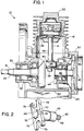
- Fig. 1 is a schematic partial cross-sectional view of a portion of an internal combustion engine incorporating features of the present invention.
- Fig. 2 is a perspective view of a starter shaft assembly shown in Fig. 1 incorporating features of the present invention.
- Fig. 3A is a cross-sectional view of a recoil starter and starter cup used in the engine shown in Fig. 1.
- Fig. 3B is a front end view of the recoil starter shown in Fig. 3A.
- FIG. 1 there is shown a schematic partial cross-sectional view of a portion of an internal combustion engine 10 incorporating features of the present invention.
- a schematic partial cross-sectional view of a portion of an internal combustion engine 10 incorporating features of the present invention.
- the present invention will be described with reference to the single embodiment shown in the drawings, it should be understood that the present invention may be embodied in many alternative forms of embodiment.
- any suitable size, shape or type of members or materials could be used.
- the engine 10 is a simple 2-cycle engine, but the present invention could be used with a 4-cycle engine.
- the engine 10 has a frame 12, a piston assembly 14, an output crankshaft 16, and an input shaft assembly 18.
- the frame 12 includes a crankcase 20 and a cylinderhead 22.
- the engine 10 includes a suitable fuel supply system and ignition control which is not shown for the sake of clarity.
- a crankcase cover 24 also forms part of the frame 12. The cover 24 is removably mounted to the crankcase 20 at an aperture into the interior of the crankcase 20, such as by means of bolts.
- the output crankshaft 16 includes an output shaft section 26 and an offset crankpin section 28.
- the crankshaft 16 is preferably made as a unitary member, but may also comprise an assembly of parts.
- Two bearings 30, 31 are provided to rotatably mount the crankshaft 16 in an aperture 32 of the crankcase 20. Two bearings are provided in order to adequately support the crankshaft 16 due to its weight and the loads it is subjected to by the piston assembly 14.
- the output shaft section 26 is connected to a suitable driven member or assembly (not shown) such as a string cutter shaft if the engine 10 is being used in a string cutter. However, the engine 10 could be used in any suitable environment.
- the offset crankpin section 28 is offset from the longitudinal axis of the output shaft section 26. Thus, when the output shaft section 26 is axially rotated, the offset crankpin section 28 moves in a general orbital path inside the crankcase 20.
- the piston assembly 14 generally comprises a piston head 34 and a pivotably attached push rod 36.
- the end 38 of the push rod 36, opposite the piston head 34, has an aperture 40.
- the aperture 40 is provided to rotatably receive and connect the crankpin section 28 to the push rod 36.
- the input shaft assembly 18 generally comprises an input shaft 42, a crank plate 44, and a starter cup 46.
- the assembly 18 is used in conjunction with the recoil starter 48 to start the engine 10.
- the recoil starter 48 is generally known in the art.
- the starter 48 is fixedly connected to the cover 24 at a mounting block 50, such as by use of screws.
- the starter 48 has a pull handle 52, line 54, spring 56, and an engaging gear 58 located inside the starter housing 60.
- the engaging gear 58 is adapted to engage the starter cup 46 when the pull handle 52 is pulled to thereby axially rotate the starter cup 46.
- the spring 56 is adapted to disengage the gear 58 from the starter cup 46 after the pull handle 52 has been pulled and also recoil the line 54 back into the housing 60.
- the input shaft 42 is preferably made of metal and includes a first end 62 and a second end 64.
- the first end 62 has threads 66 to connect the input shaft 42 to a center aperture 68 of the starter cup 46.
- the second end 64 of the input shaft 42 includes a notch 70 and a beveled leading edge 72.
- the crank plate 44 is also preferably made of metal and includes a center aperture 74 and two slightly elongate open ended U-shaped slots 76 offset from the center aperture 74 on opposite ends of the crank plate 44. As seen best in Fig. 2, the crank plate 44 is comprised of a substantially symmetrical flat sheet of metal.
- the aperture 74 includes a flat section 78 such that the aperture 74 is substantially identical to a cross-section of the input shaft 42.
- the width of the slots 76 is substantially the same as the cross-sectional width of the crankpin 28.
- the crank plate 44 is fixedly and stationarily mounted to the second end 64 of the input shaft 42 by means of a press-fit mounting.
- the input shaft 42 is aligned in front of the center aperture 74 with the notch 70 and flat section 78 aligned.
- the input shaft 42 and crank plate 44 are then merely pressed together such that the crank plate 44 mounts onto the shaft 42.
- the beveled leading edge 72 assists in initial mounting.
- the aperture 74 and outer shape of the shaft 42 at its second end 64 are suitably sized to insure a tight press-fit connection of the crank plate 44 on the shaft 42.
- the notch 70 and section 78 function as keys to prevent the crank plate 44 from axially rotating on the shaft second end 64.
- any suitable type of keying means or anti-rotation means could be provided.
- the input shaft 42 is rotatably mounted in the crankcase cover 24 by means of a single bearing 80. However, in an alternative embodiment two or more bearings could be provided for the input shaft 42. A seal 82 is also provided.
- the crank plate 44 is located inside the crankcase 20 with an end of the crankpin section 28 located in one of the slots 76.
- the input shaft 42 extends through the crankcase cover 24 and has the starter cup 46 fixedly attached to its second end 62.
- the assembly 18 due to the simple configuration of the input shaft assembly 18, the assembly 18 has a relatively light weight.
- the assembly 18 is also substantially symmetrical about its axis of rotation. The combination of these factors helps to reduce dynamic forces of the assembly 18 when being rotated.
- crank plate 44 and crankpin section 28 greatly reduces eccentric forces by the crankpin section 28 on the assembly 18. This is accomplished due to the fact that the slots 76 are suitably sized and shaped relative to the end of the crankpin section 28 to allow crankpin section 28 to move in its slot 76. Thus, even if the crankpin section 28 has a slightly irregular path of rotation, this will not substantially affect rotation of the assembly 18 or apply undesired eccentric loads on the assembly 18. This improvement allows the assembly 18 to be mounted to the crankcase cover 24 with only one bearing 80 rather than having to need two bearings as in the prior art. This obviously reduces the cost of manufacturing and assembling the engine 10 compared to prior art engines.
- crank plate 44 can be made from a simple flat steel stamping or a powder metal part and is symmetric for balance.
- the U-shaped slots 76 also allow for easy engagement of the crankpin section 28 during assembly and lessen the need for accurate alignment between the input shaft assembly 18 and crankshaft 16.
- the present invention also reduces eccentric forces on the assembly 18 during starting of the engine 10 by the recoil starter 48.
- crank plate 44 has been described in some detail above, it should be noted that other embodiments are easily envisioned such as with more or less than two slots, slots that are shaped other than with open ended U-shapes, and slots that do not extend entirely through the crank plate.
Landscapes
- Engineering & Computer Science (AREA)
- General Engineering & Computer Science (AREA)
- Mechanical Engineering (AREA)
- Chemical & Material Sciences (AREA)
- Combustion & Propulsion (AREA)
- Ocean & Marine Engineering (AREA)
- Shafts, Cranks, Connecting Bars, And Related Bearings (AREA)
- Cylinder Crankcases Of Internal Combustion Engines (AREA)
Applications Claiming Priority (2)
| Application Number | Priority Date | Filing Date | Title |
|---|---|---|---|
| US11266 | 1993-01-29 | ||
| US08/011,266 US5333580A (en) | 1993-01-29 | 1993-01-29 | Starter input shaft |
Publications (2)
| Publication Number | Publication Date |
|---|---|
| EP0609094A1 true EP0609094A1 (de) | 1994-08-03 |
| EP0609094B1 EP0609094B1 (de) | 1998-06-03 |
Family
ID=21749607
Family Applications (1)
| Application Number | Title | Priority Date | Filing Date |
|---|---|---|---|
| EP94300647A Expired - Lifetime EP0609094B1 (de) | 1993-01-29 | 1994-01-28 | Brennkraftmaschine |
Country Status (5)
| Country | Link |
|---|---|
| US (1) | US5333580A (de) |
| EP (1) | EP0609094B1 (de) |
| JP (1) | JP3335457B2 (de) |
| CA (1) | CA2114245C (de) |
| DE (1) | DE69410646T2 (de) |
Cited By (2)
| Publication number | Priority date | Publication date | Assignee | Title |
|---|---|---|---|---|
| EP0887528A3 (de) * | 1997-06-25 | 1999-08-18 | Mitsubishi Heavy Industries, Ltd. | Universelle luftgekühlte Viertakt-Brennkraftmaschine |
| DE202008012296U1 (de) | 2008-09-17 | 2009-02-19 | Era-Tec Gmbh | Doppelwandiges Trinkgefäß |
Families Citing this family (5)
| Publication number | Priority date | Publication date | Assignee | Title |
|---|---|---|---|---|
| US6253722B1 (en) | 1998-11-06 | 2001-07-03 | Alliedsignal Inc. | Starting apparatus for internal combustion engines |
| SE9904702L (sv) * | 1998-12-28 | 2000-06-29 | Stihl Maschf Andreas | Kortslagig förbränningsmotor |
| US6536396B1 (en) | 1999-06-09 | 2003-03-25 | Honeywell International Inc. | Starting device for internal combustion engines |
| US6782863B2 (en) | 2002-10-08 | 2004-08-31 | Mtd Products Inc. | Spring release starter |
| USD611411S1 (en) * | 2008-07-29 | 2010-03-09 | Wesley Harmelink | Engine recoil handle |
Citations (3)
| Publication number | Priority date | Publication date | Assignee | Title |
|---|---|---|---|---|
| US3147638A (en) * | 1961-05-01 | 1964-09-08 | Ohlsson & Rice Inc | Crankshaft apparatus |
| JPS59115429A (ja) * | 1982-12-23 | 1984-07-03 | Kawasaki Heavy Ind Ltd | エンジン |
| FR2633665A1 (fr) * | 1988-07-01 | 1990-01-05 | Kioritz Corp | Moteur a combustion interne a deux temps du type a lubrification paree |
Family Cites Families (11)
| Publication number | Priority date | Publication date | Assignee | Title |
|---|---|---|---|---|
| US1753196A (en) * | 1927-04-27 | 1930-04-08 | Siemens Ag | Internal-combustion engine |
| US2204750A (en) * | 1938-12-19 | 1940-06-18 | Outboard Marine & Mfg Co | Mechanical starter for internal combustion engines |
| US2597334A (en) * | 1945-09-06 | 1952-05-20 | Scott Atwater Mfg Company | Starting device for outboard motors |
| US2480550A (en) * | 1947-10-28 | 1949-08-30 | Robert V Catlin | Automatic recoiling pull starter |
| US3747649A (en) * | 1971-02-08 | 1973-07-24 | Outboard Marine Corp | Crankshaft magneto system |
| US3782355A (en) * | 1971-07-29 | 1974-01-01 | Eaton Stamping Co | Recoil starter |
| US3871350A (en) * | 1971-07-29 | 1975-03-18 | Eaton Stamping Co | Recoil starter |
| US4342236A (en) * | 1978-09-27 | 1982-08-03 | Everts Robert G | Crankshaft with laminated counterweight |
| US4356605A (en) * | 1978-09-27 | 1982-11-02 | Everts Robert G | Crankshaft with laminated counterweight |
| US4492190A (en) * | 1983-04-20 | 1985-01-08 | Eaton Stamping Company | Recoil starter |
| JPS6458808A (en) * | 1987-08-31 | 1989-03-06 | Kioritz Corp | Crank |
-
1993
- 1993-01-29 US US08/011,266 patent/US5333580A/en not_active Expired - Lifetime
-
1994
- 1994-01-25 CA CA002114245A patent/CA2114245C/en not_active Expired - Fee Related
- 1994-01-28 EP EP94300647A patent/EP0609094B1/de not_active Expired - Lifetime
- 1994-01-28 JP JP00861994A patent/JP3335457B2/ja not_active Expired - Fee Related
- 1994-01-28 DE DE69410646T patent/DE69410646T2/de not_active Expired - Lifetime
Patent Citations (3)
| Publication number | Priority date | Publication date | Assignee | Title |
|---|---|---|---|---|
| US3147638A (en) * | 1961-05-01 | 1964-09-08 | Ohlsson & Rice Inc | Crankshaft apparatus |
| JPS59115429A (ja) * | 1982-12-23 | 1984-07-03 | Kawasaki Heavy Ind Ltd | エンジン |
| FR2633665A1 (fr) * | 1988-07-01 | 1990-01-05 | Kioritz Corp | Moteur a combustion interne a deux temps du type a lubrification paree |
Non-Patent Citations (1)
| Title |
|---|
| PATENT ABSTRACTS OF JAPAN vol. 8, no. 234 (M - 334) 26 October 1984 (1984-10-26) * |
Cited By (3)
| Publication number | Priority date | Publication date | Assignee | Title |
|---|---|---|---|---|
| EP0887528A3 (de) * | 1997-06-25 | 1999-08-18 | Mitsubishi Heavy Industries, Ltd. | Universelle luftgekühlte Viertakt-Brennkraftmaschine |
| US6058894A (en) * | 1997-06-25 | 2000-05-09 | Mitsubishi Heavy Industries, Ltd. | General-purpose air-cooled four-cycle engine |
| DE202008012296U1 (de) | 2008-09-17 | 2009-02-19 | Era-Tec Gmbh | Doppelwandiges Trinkgefäß |
Also Published As
| Publication number | Publication date |
|---|---|
| CA2114245C (en) | 2005-05-17 |
| DE69410646D1 (de) | 1998-07-09 |
| DE69410646T2 (de) | 1998-10-01 |
| EP0609094B1 (de) | 1998-06-03 |
| US5333580A (en) | 1994-08-02 |
| CA2114245A1 (en) | 1994-07-30 |
| JPH06294368A (ja) | 1994-10-21 |
| JP3335457B2 (ja) | 2002-10-15 |
Similar Documents
| Publication | Publication Date | Title |
|---|---|---|
| CA1056678A (en) | Apparatus for shock mounting of piston rods in internal combustion engines and the like | |
| CA2488711C (en) | Energy storing starter assembly | |
| CA2071458C (en) | 4-cycle engine | |
| EP2131035B1 (de) | Seilstartsystem für Verbrennungsmotor mit Energiespeicherung | |
| US5333580A (en) | Starter input shaft | |
| GB2173547A (en) | Valve gear for four-cycle engine | |
| EP0428187A2 (de) | Tragbare Maschineneinheit | |
| EP3524794B1 (de) | Hubkolbenmechanismus | |
| US5605077A (en) | Camshaft supporting structure in an engine | |
| US5884599A (en) | Engine with balancers for vehicle | |
| CA1166039A (en) | Electric starter with confined cushion | |
| US4624156A (en) | Crankshaft assembly | |
| US5184402A (en) | Method of installing roller bearing | |
| JP2010007484A (ja) | バランスシャフトを備えた内燃機関 | |
| JP2003083080A (ja) | カムチェーンの脱落防止構造 | |
| KR960010263B1 (ko) | 커넥팅 로드/크랭크 축의 동력전달장치 | |
| US6293243B1 (en) | Short-stroke internal combustion engine | |
| EP0891477B1 (de) | Vorrichtung zur erhöhung der vedichtung eines kurbelgehäuses eines verbrennungsmotors | |
| US6435151B1 (en) | Decompressor for four-stroke cycle engine | |
| JPS5916490Y2 (ja) | 内燃機関におけるカム軸の軸受装置 | |
| JPS6332997Y2 (de) | ||
| JP2600591Y2 (ja) | エンジンの補機駆動用伝動機構 | |
| US20030094162A1 (en) | Engine air-assisted injection compressor drive | |
| JP3395187B2 (ja) | 二サイクルエンジンのバランサー装置 | |
| JPH08121540A (ja) | エンジンのバランサドライブギヤ取付構造 |
Legal Events
| Date | Code | Title | Description |
|---|---|---|---|
| PUAI | Public reference made under article 153(3) epc to a published international application that has entered the european phase |
Free format text: ORIGINAL CODE: 0009012 |
|
| AK | Designated contracting states |
Kind code of ref document: A1 Designated state(s): DE FR GB IT SE |
|
| 17P | Request for examination filed |
Effective date: 19950117 |
|
| 17Q | First examination report despatched |
Effective date: 19951121 |
|
| GRAG | Despatch of communication of intention to grant |
Free format text: ORIGINAL CODE: EPIDOS AGRA |
|
| GRAG | Despatch of communication of intention to grant |
Free format text: ORIGINAL CODE: EPIDOS AGRA |
|
| GRAG | Despatch of communication of intention to grant |
Free format text: ORIGINAL CODE: EPIDOS AGRA |
|
| GRAH | Despatch of communication of intention to grant a patent |
Free format text: ORIGINAL CODE: EPIDOS IGRA |
|
| GRAH | Despatch of communication of intention to grant a patent |
Free format text: ORIGINAL CODE: EPIDOS IGRA |
|
| GRAA | (expected) grant |
Free format text: ORIGINAL CODE: 0009210 |
|
| ITF | It: translation for a ep patent filed | ||
| RAP1 | Party data changed (applicant data changed or rights of an application transferred) |
Owner name: DEERE & COMPANY |
|
| AK | Designated contracting states |
Kind code of ref document: B1 Designated state(s): DE FR GB IT SE |
|
| REF | Corresponds to: |
Ref document number: 69410646 Country of ref document: DE Date of ref document: 19980709 |
|
| ET | Fr: translation filed | ||
| PLBE | No opposition filed within time limit |
Free format text: ORIGINAL CODE: 0009261 |
|
| STAA | Information on the status of an ep patent application or granted ep patent |
Free format text: STATUS: NO OPPOSITION FILED WITHIN TIME LIMIT |
|
| 26N | No opposition filed | ||
| REG | Reference to a national code |
Ref country code: GB Ref legal event code: IF02 |
|
| PGFP | Annual fee paid to national office [announced via postgrant information from national office to epo] |
Ref country code: SE Payment date: 20080124 Year of fee payment: 15 Ref country code: IT Payment date: 20080124 Year of fee payment: 15 |
|
| EUG | Se: european patent has lapsed | ||
| PG25 | Lapsed in a contracting state [announced via postgrant information from national office to epo] |
Ref country code: IT Free format text: LAPSE BECAUSE OF NON-PAYMENT OF DUE FEES Effective date: 20090128 |
|
| PG25 | Lapsed in a contracting state [announced via postgrant information from national office to epo] |
Ref country code: SE Free format text: LAPSE BECAUSE OF NON-PAYMENT OF DUE FEES Effective date: 20090129 |
|
| PGFP | Annual fee paid to national office [announced via postgrant information from national office to epo] |
Ref country code: DE Payment date: 20110126 Year of fee payment: 18 Ref country code: FR Payment date: 20110217 Year of fee payment: 18 |
|
| PGFP | Annual fee paid to national office [announced via postgrant information from national office to epo] |
Ref country code: GB Payment date: 20110126 Year of fee payment: 18 |
|
| GBPC | Gb: european patent ceased through non-payment of renewal fee |
Effective date: 20120128 |
|
| REG | Reference to a national code |
Ref country code: FR Ref legal event code: ST Effective date: 20120928 |
|
| PG25 | Lapsed in a contracting state [announced via postgrant information from national office to epo] |
Ref country code: GB Free format text: LAPSE BECAUSE OF NON-PAYMENT OF DUE FEES Effective date: 20120128 Ref country code: DE Free format text: LAPSE BECAUSE OF NON-PAYMENT OF DUE FEES Effective date: 20120801 |
|
| REG | Reference to a national code |
Ref country code: DE Ref legal event code: R119 Ref document number: 69410646 Country of ref document: DE Effective date: 20120801 |
|
| PG25 | Lapsed in a contracting state [announced via postgrant information from national office to epo] |
Ref country code: FR Free format text: LAPSE BECAUSE OF NON-PAYMENT OF DUE FEES Effective date: 20120131 |