EP0609520B1 - Perforator für Metallplatten - Google Patents
Perforator für Metallplatten Download PDFInfo
- Publication number
- EP0609520B1 EP0609520B1 EP93119680A EP93119680A EP0609520B1 EP 0609520 B1 EP0609520 B1 EP 0609520B1 EP 93119680 A EP93119680 A EP 93119680A EP 93119680 A EP93119680 A EP 93119680A EP 0609520 B1 EP0609520 B1 EP 0609520B1
- Authority
- EP
- European Patent Office
- Prior art keywords
- punch
- plate
- assembly
- die
- retaining
- Prior art date
- Legal status (The legal status is an assumption and is not a legal conclusion. Google has not performed a legal analysis and makes no representation as to the accuracy of the status listed.)
- Expired - Lifetime
Links
- 229910052751 metal Inorganic materials 0.000 title claims description 35
- 239000002184 metal Substances 0.000 title claims description 35
- 239000000463 material Substances 0.000 claims description 25
- 229910052782 aluminium Inorganic materials 0.000 claims description 8
- XAGFODPZIPBFFR-UHFFFAOYSA-N aluminium Chemical compound [Al] XAGFODPZIPBFFR-UHFFFAOYSA-N 0.000 claims description 8
- 230000032258 transport Effects 0.000 claims description 4
- 229910021385 hard carbon Inorganic materials 0.000 claims description 3
- 230000003746 surface roughness Effects 0.000 claims description 2
- 230000006835 compression Effects 0.000 claims 1
- 238000007906 compression Methods 0.000 claims 1
- 239000011347 resin Substances 0.000 claims 1
- 229920005989 resin Polymers 0.000 claims 1
- 238000004080 punching Methods 0.000 description 24
- 238000002474 experimental method Methods 0.000 description 7
- -1 polyethylene Polymers 0.000 description 7
- 229910000997 High-speed steel Inorganic materials 0.000 description 5
- 239000004698 Polyethylene Substances 0.000 description 5
- 229920000573 polyethylene Polymers 0.000 description 5
- 230000006378 damage Effects 0.000 description 4
- 239000000428 dust Substances 0.000 description 4
- 230000007723 transport mechanism Effects 0.000 description 4
- OKTJSMMVPCPJKN-UHFFFAOYSA-N Carbon Chemical compound [C] OKTJSMMVPCPJKN-UHFFFAOYSA-N 0.000 description 3
- 229910000831 Steel Inorganic materials 0.000 description 3
- 229910001315 Tool steel Inorganic materials 0.000 description 3
- 229910052799 carbon Inorganic materials 0.000 description 3
- 239000002440 industrial waste Substances 0.000 description 3
- 229920000139 polyethylene terephthalate Polymers 0.000 description 3
- 239000005020 polyethylene terephthalate Substances 0.000 description 3
- 239000010959 steel Substances 0.000 description 3
- 238000004140 cleaning Methods 0.000 description 2
- 239000011248 coating agent Substances 0.000 description 2
- 238000000576 coating method Methods 0.000 description 2
- 238000007689 inspection Methods 0.000 description 2
- 238000004519 manufacturing process Methods 0.000 description 2
- 230000007246 mechanism Effects 0.000 description 2
- 238000012986 modification Methods 0.000 description 2
- 230000004048 modification Effects 0.000 description 2
- 239000000843 powder Substances 0.000 description 2
- 230000000630 rising effect Effects 0.000 description 2
- 239000002699 waste material Substances 0.000 description 2
- 239000004411 aluminium Substances 0.000 description 1
- 238000000429 assembly Methods 0.000 description 1
- 230000000712 assembly Effects 0.000 description 1
- 239000010953 base metal Substances 0.000 description 1
- 230000015572 biosynthetic process Effects 0.000 description 1
- 238000005524 ceramic coating Methods 0.000 description 1
- 230000003247 decreasing effect Effects 0.000 description 1
- 238000001459 lithography Methods 0.000 description 1
- 230000000750 progressive effect Effects 0.000 description 1
- 239000005028 tinplate Substances 0.000 description 1
Images




Classifications
-
- B—PERFORMING OPERATIONS; TRANSPORTING
- B21—MECHANICAL METAL-WORKING WITHOUT ESSENTIALLY REMOVING MATERIAL; PUNCHING METAL
- B21D—WORKING OR PROCESSING OF SHEET METAL OR METAL TUBES, RODS OR PROFILES WITHOUT ESSENTIALLY REMOVING MATERIAL; PUNCHING METAL
- B21D37/00—Tools as parts of machines covered by this subclass
- B21D37/01—Selection of materials
-
- B—PERFORMING OPERATIONS; TRANSPORTING
- B21—MECHANICAL METAL-WORKING WITHOUT ESSENTIALLY REMOVING MATERIAL; PUNCHING METAL
- B21D—WORKING OR PROCESSING OF SHEET METAL OR METAL TUBES, RODS OR PROFILES WITHOUT ESSENTIALLY REMOVING MATERIAL; PUNCHING METAL
- B21D28/00—Shaping by press-cutting; Perforating
- B21D28/02—Punching blanks or articles with or without obtaining scrap; Notching
- B21D28/14—Dies
-
- B—PERFORMING OPERATIONS; TRANSPORTING
- B21—MECHANICAL METAL-WORKING WITHOUT ESSENTIALLY REMOVING MATERIAL; PUNCHING METAL
- B21D—WORKING OR PROCESSING OF SHEET METAL OR METAL TUBES, RODS OR PROFILES WITHOUT ESSENTIALLY REMOVING MATERIAL; PUNCHING METAL
- B21D28/00—Shaping by press-cutting; Perforating
- B21D28/02—Punching blanks or articles with or without obtaining scrap; Notching
- B21D28/16—Shoulder or burr prevention, e.g. fine-blanking
-
- B—PERFORMING OPERATIONS; TRANSPORTING
- B21—MECHANICAL METAL-WORKING WITHOUT ESSENTIALLY REMOVING MATERIAL; PUNCHING METAL
- B21D—WORKING OR PROCESSING OF SHEET METAL OR METAL TUBES, RODS OR PROFILES WITHOUT ESSENTIALLY REMOVING MATERIAL; PUNCHING METAL
- B21D45/00—Ejecting or stripping-off devices arranged in machines or tools dealt with in this subclass
- B21D45/003—Ejecting or stripping-off devices arranged in machines or tools dealt with in this subclass in punching machines or punching tools
- B21D45/006—Stripping-off devices
-
- Y—GENERAL TAGGING OF NEW TECHNOLOGICAL DEVELOPMENTS; GENERAL TAGGING OF CROSS-SECTIONAL TECHNOLOGIES SPANNING OVER SEVERAL SECTIONS OF THE IPC; TECHNICAL SUBJECTS COVERED BY FORMER USPC CROSS-REFERENCE ART COLLECTIONS [XRACs] AND DIGESTS
- Y10—TECHNICAL SUBJECTS COVERED BY FORMER USPC
- Y10T—TECHNICAL SUBJECTS COVERED BY FORMER US CLASSIFICATION
- Y10T83/00—Cutting
- Y10T83/04—Processes
- Y10T83/06—Blanking
-
- Y—GENERAL TAGGING OF NEW TECHNOLOGICAL DEVELOPMENTS; GENERAL TAGGING OF CROSS-SECTIONAL TECHNOLOGIES SPANNING OVER SEVERAL SECTIONS OF THE IPC; TECHNICAL SUBJECTS COVERED BY FORMER USPC CROSS-REFERENCE ART COLLECTIONS [XRACs] AND DIGESTS
- Y10—TECHNICAL SUBJECTS COVERED BY FORMER USPC
- Y10T—TECHNICAL SUBJECTS COVERED BY FORMER US CLASSIFICATION
- Y10T83/00—Cutting
- Y10T83/929—Tool or tool with support
- Y10T83/9411—Cutting couple type
- Y10T83/9423—Punching tool
- Y10T83/9428—Shear-type male tool
Definitions
- the present invention relates to an assembly comprising a metal plate and an apparatus for forming a hole in said metal plate of the type as defined in the preamble of claim 1.
- Assemblies for hole forming by punching are widely known in the art, for instance from US-A-2,763,325 which shows an assembly of the type as defined in the preamble of claim 1.
- the known assembly includes a punch means and die means co-operating with each other.
- the effective end of the punch means has a diameter corresponding to the diameter of the hole to be formed. Requirements with respect to the surface quality and clearance are neither mentioned to be important nor described by specific features.
- JP-A-63-203 223 describes an apparatus for coating the surface of a base metal used for forming punch means by a ceramic coating.
- the punch means coated is not described.
- a lithographic printing system is generally operated by utilising a presentized plate (herein referred to as a PS plate), which comprises a support consisting of a thin metal plate of e.g. aluminium or steel.
- a PS plate which comprises a support consisting of a thin metal plate of e.g. aluminium or steel.
- Such a PS plate processed for lithography is mounted in a printer.
- the PS plate is provided with punched holes to receive positioning members.
- a perforator is used for punching the plate material.
- the perforator is a moveable blade or punch shaped to punch a hole in order to pierce the plate material, and a stationary blade or die for slidably receiving the punch.
- the plate material is continuous or is a separate piece and is sandwiched between the punch and the die so as to punch holes in the plate material.
- Such a perforator is usable to punch simultaneously plural superposed pieces of material.
- the punch and die should be sufficiently hard, should have each blade precisely constructed, and should have sufficiently small roughness on the faces of the blades. It is usual to form the punch from high speed steel SKH, and to form the die from special tool steel SKD, and to set the roughness on the blade faces to be 2,0 ⁇ m, preferably as small as 1.0 ⁇ m. It is general to provide clearance between the punch and the die, of 5 to 8% of the thickness of the plate material to be punched.
- an object of the present invention is to provide an assembly comprising a metal plate and an apparatus for forming an hole in said metal plate of high performance and great durability, avoiding the need for unwanted disposal of industrial waste.
- the punch means and/or die means is coated with non-crystalline hard carbon having a surface roughness as low as 0.8 ⁇ m or less.
- the clearance between the punch means and the die means is up to 10 to 30% of the thickness of the plate material.
- Each advancing end of the punch means is provided with a cylindrical tip portion having a reduced width.
- the retaining means is provided with cushioning material mounted for contact with the plate material.
- This assembly has high performance during perforating operations and durability over long use. Even when the punching operation is repeated, there is little dust generated from the plate material. No irregularities appear along the punched edges of the punched holes. Even after the punches are raised and removed from the punched holes, no unwanted raised edges or folds around the punched holes are generated, even upon repeated use of the novel perforator. The quality of PS plates as products is maintained without decreasing.
- the use of the perforator does not require frequent inspection or cleaning of the blade faces. Efficiency of punching is greatly improved.
- the sheet perforator has a drive mechanism 10 including a motor.
- a punch holder 12 is connected via a pair of guiding rods 13 to the drive mechanism 10, and is drivable to move up and down.
- On the punch holder 12 are arranged a number of, e.g. seven, punches 14 extending downward and formed e.g. from high speed steel SKH.
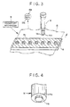
- a transport mechanism 9 (see Fig. 3) transports a rectangular thin flat metal sheet 15, and inserts it under the punches 14.
- the metal sheet 15 is placed on a die array 16 formed e.g. from special tool steel SKD.
- the punches 14 arc inserted into the die array 16, until the punches 14 and the die array 16 cut the metal sheet 15 to form punch holes shaped to be round or elliptical.
- the die array 16 has die holes 16a whose inner diameter or width is substantially equal to the width of the punch 14.
- the metal sheet 15 is punched when the die holes 16a receive the advancing punches 14.
- the die array 16 is supported on a die holder 17. After the metal sheet 15 is punched, the waste bits of the metal sheet 15 are discharged through openings 1 7a.
- a stripper plate 18 is disposed fixedly on the die array 16. The metal sheet 15 is inserted between the stripper plate 18 and the die array 16. When the punch holder 12 is raised after punching the metal sheet 15, the stripper plate 18 contacts the metal sheet 15, separates the rising punches 14 from the metal sheet 15, and keeps the metal sheet 15 from rising with the punches 14.
- the bottom of the stripper plate 18 has a cushioning material 19 for contact with the metal sheet 15.
- the cushioning material 19 consists of a sheet of polyethylene terephthalate (PET) 170 ⁇ m thick. Note that, after the punches 14 are retracted from the metal sheet 15, the transport mechanism 9 moves the metal sheet 15 from between the die array 16 and the punches 14.
- the metal sheet 15 is constituted of a PS plate 15a and a light-shielding lining sheet 15b attached thereto.
- a punching blade edge 14a around the punches 14, the top face of the die array 16, and the inside of the die holes 16a is coated with non-crystalline hard carbon.
- the punches 14 or the die array 16 may lack such a coating, it is preferred to coat both.
- the roughness of the carbon coat of those faces is 0.8 ⁇ m or less. As illustrated in Figs.
- the punches 14 each have a stepped tip portion 14b shaped as a cylinder smaller in diameter than the main body of the punch, thereby reducing the distortion or unwanted raised margin about the punched hole.
- the height H of the tip portion 14b is at least half the thickness of the metal sheet 15, and at most twice that thickness.
- the clearance C as shown is half of the difference between diameters of the punch 14 and the die hole 16a, and is in the range of 10 to 30% of the thickness of the metal sheet 15. Note that the perforator may lack the transport mechanism 9 and instead be fed manually.
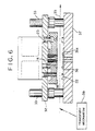
- Fig. 6 illustrates a preferred web perforator, in which a continuous web 35 constituted of PS plate and light-shielding lining paper is repeatedly punched in synchronism with the intermittent progressive conveyance of the web 35 by a transport mechanism 39. Elements similar to those of the sheet perforator in Figs. 1 and 2 are designated with the identical numerals.
- a stripper plate 38 is slidably mounted on a punch holder 32. When the punch holder 32 Is lowered, the stripper plate 38 comes into contact with a stopper 22. Subsequently, the punch holder 32 is lowered against the bias of a stripper spring 23, until the punches 14 punch the web 35. After punching, the punch holder 32 with the punches 14 Is raised, and the stripper plate 38 is raised.
- reference numeral 33 designates guiding rods, 36 a die array, and 37 a die holder.
- the punches and die array to be used in the present invention can be formed, not only from the high speed steel SKH or the special tool steel SKD above described, but from sufficiently hard other steels, such as various high speed steels and high speed steel powder. It is also possible to construct punches differently: the punch 25 in Fig. 7 has a conical tip portion 25a; the punch 26 in Fig. 8 has a truncated conical tip portion 26a; and the punch 27 in Fig. 9 has a quadrangular stepped tip portion 27a.
- punched holes formed in the above embodiments are round, alternatively punched holes shaped like slots having round corners can be formed, by use of punches shaped correspondingly.
- the metal sheets and web constitute PS aluminum plates in the above embodiment, the present invention is applicable to punching PS steel plates.
Landscapes
- Engineering & Computer Science (AREA)
- Mechanical Engineering (AREA)
- Chemical & Material Sciences (AREA)
- Materials Engineering (AREA)
- Perforating, Stamping-Out Or Severing By Means Other Than Cutting (AREA)
Claims (18)
- Eine Anordnung mit einer Metallplatte (15, 35) und einem Gerät zur Bildung eines Loches in der Metallplatte, wobei das Gerät eine bewegliche Stempeleinrichtung (14, 25, 26, 27), Matrizeneinrichtung (16, 36), die mit der beweglichen Stempeleinrichtung zusammenwirkt, und eine Festhalteeinrichtung (18, 38) aufweist zum Festhalten der Platte benachbart zu der Matrizeneinrichtung, wenn sich die Stempeleinrichtung von der Matrizeneinrichtung trennt, nachdem die Stempeleinrichtung das Loch in die Platte gebildet hat; dadurch gekennzeichnet, daß zum Bilden eines Loches in eine vorsensibilisierte lithographische Metallplatte, bedeckt mit einem abschirmenden Beschichtungspapier, wobei das Papier ein reines Zellulosepapier oder ein Kunststoffhaltiges Papier ist, die bewegliche Stempeleinrichtung (14, 25, 26, 27) dem Beschichtungspapier der Metallplatte, aufgenommen in dem Gerät, zugewandt ist, wobei zumindest entweder die Stempeleinrichtung oder die Matrizeneinrichtung mit nicht-kristallinem, harten Kohlenstoff beschichtet ist, der eine Oberflächenrauhigkeit von 0.8 µm oder weniger hat, ein Spalt zwischen der Stempeleinrichtung (14, 25, 26, 27) und der Matrizeneinrichtung (16, 36) zwischen 10 und 30 % der Dicke der Platte (15, 35) beträgt und ein vorauslaufendes Ende der Stempeleinrichtung (14, 25, 26, 27) ist mit einem Spitzenabschnitt (14b, 25a, 26a, 27a) versehen ist, der Breite, die geringer als die Breite der restlichen Stempeleinrichtung ist und kleiner ist, als ein Matrizenloch in der Matrizeneinrichtung.
- Eine Anordnung nach Anspruch 1, wobei die Stempeleinrichtung (14, 25, 26, 27) zumindest einen Stempel hat und die Matrizeneinrichtung (16, 36) zumindest ein Matrizenloch hat, in das der Stempel eingesetzt ist.
- Eine Anordnung nach Anspruch 1 oder 2, wobei die Halteeinrichtung (18, 38) eine einzelne Platte ist, die ein Loch hat, durch das sich der Stempel (14, 25, 26, 27) erstreckt.
- Eine Anordnung nach einem der Ansprüche 1 bis 3, die außerdem eine Transporteinrichtung (9, 39) zum Transport der Platte zu der Matrize aufweist.
- Eine Anordnung nach einem der Ansprüche 1 bis 4, wobei die Platte (15, 35) aus einem Stück ist.
- Eine Anordnung nach Anspruch 4, wobei die Platte (15, 35) fortlaufend ist, die Transporteinrichtung (9, 39) transportiert die Platte intermittierend und der Stempel (14, 25, 26, 27) wird nach jedem Schritt des intermittierenden Transports angetrieben.
- Eine Anordnung nach einem der Ansprüche 1 bis 6, weiter aufweisend:eine bewegliche Haltevorrichtung (12, 32), an der die Stempeleinrichtung (14, 25, 26, 27) und die Festhalteeinrichtung (18, 38) montiert sind; undeine Antriebseinrichtung (10) zum Bewegen der Halteeinrichtung, wobei die Festhalteeinrichtung der Platten (15, 35) in Kontakt kommen, während die Halteeinrichtung durch die Antriebseinrichtung in Richtung der Matrize (16, 36) bewegt wird, wobei die Halteeinrichtung anschließend sich in Richtung zu der Matrize hinbewegt und die Stempeleinrichtung sich über die Festhalteeinrichtung hinaus vorwärts bewegt.
- Eine Anordnung nach Anspruch 7, die außerdem aufweist eine Verbindungseinrichtung zum Verbinden der Festhalteeinrichtung (18, 38), mit als Halteeinrichtung um es der Festhalteeinrichtung (12, 32) zu gestatten, während des Kontaktes mit der Platte (15, 35) sich in eine erste Position zu verschieben, in der die Festhalteeinrichtung relativ nah zu der Halteeinrichtung ist, und nun auf die Festhalteeinrichtung eine Bewegung der Halteeinrichtung weg von der Matrize zu übertragen, während die Festhalteeinrichtung in eine zweite Position verschoben wird, in der die Festhalteeinrichtung weiter von der Haltemitteln entfernt ist, als in der ersten Position; und
wobei die Halteeinrichtung so bewegt wird, daß der Stempel von der Platte zurückgezogen wird, und so daß die Festhalteeinrichtung von der ersten Position zu der zweiten Position verschoben wird, und anschließend die Verbindungseinrichtung die Bewegung der Halteeinrichtung auf die Festhalteeinrichtung überträgt, die Festhalteinrichtung zusammen mit dem Stempel zurückzuziehen. - Eine Anordnung nach Anspruch 7 mit außerdem einer Vorspanneinrichtung (23), angeordnet zwischen der Festhalteeinrichtung und der Halteeinrichtung, um während des Kontaktes der Festhalteeinrichtung mit der Platte zusammengedrückt zu werden und um sich von dem Zusammendrücken bei Rückzug der Festhalteeinrichtung wieder zu erholen, wobei die Vorspanneinrichtung die Festhalteeinrichtung in Kontakt mit der Platte hält, während der Stempel von der Platte zurückgezogen ist.
- Eine Anordnung nach einem der Ansprüche 7 bis 9, wobei die Stanzeinrichtung (14, 25, 26, 27) eine Mehrzahl von Stempeln aufweist.
- Eine Anordnung nach einem der Ansprüche 1 bis 10, wobei die Festhalteeinrichtung (18, 38) mit einem polsterndem Material (19) versehen ist, montiert zum Kontakt mit dem Plattenmaterial (15, 35).
- Eine Anordnung nach Anspruch 11, wobei das polsternde Material ein Kunststoffblatt einschließt.
- Eine Anordnung nach einem der Ansprüche 1 bis 12, wobei das Plattenmaterial Aluminium ist.
- Eine Anordnung nach einem der Ansprüche 1 bis 13, wobei der Spitzenabschnitt (14b, 25a, 26a, 27a) der Stanzeinrichtung 0.5 bis 2.0 mal so lang wie die Dicke des Plattenmaterials ist.
- Eine Anordnung nach einem der Ansprüche 1 bis 14, wobei der Spitzenabschnitt konisch ist.
- Eine Anordnung nach einem der Ansprüche 1 bis 14, wobei der Spitzenabschnitt kegelstumpfförmig ausgebildet ist.
- Eine Anordnung nach einem der Ansprüche 1 bis 14, wobei der Spitzenabschnitt zylindrisch ist.
- Eine Anordnung nach einem der Ansprüche 1 bis 14, wobei der Spitzenabschnitt prismatisch ist.
Applications Claiming Priority (3)
| Application Number | Priority Date | Filing Date | Title |
|---|---|---|---|
| JP32698392 | 1992-12-07 | ||
| JP32698392 | 1992-12-07 | ||
| JP326983/92 | 1992-12-07 |
Publications (2)
| Publication Number | Publication Date |
|---|---|
| EP0609520A1 EP0609520A1 (de) | 1994-08-10 |
| EP0609520B1 true EP0609520B1 (de) | 2001-05-23 |
Family
ID=18193994
Family Applications (1)
| Application Number | Title | Priority Date | Filing Date |
|---|---|---|---|
| EP93119680A Expired - Lifetime EP0609520B1 (de) | 1992-12-07 | 1993-12-07 | Perforator für Metallplatten |
Country Status (3)
| Country | Link |
|---|---|
| US (1) | US5992280A (de) |
| EP (1) | EP0609520B1 (de) |
| DE (1) | DE69330244T2 (de) |
Families Citing this family (26)
| Publication number | Priority date | Publication date | Assignee | Title |
|---|---|---|---|---|
| JP3676192B2 (ja) * | 2000-05-26 | 2005-07-27 | 本田技研工業株式会社 | 無段変速機用ベルトのエレメントの打抜き加工方法 |
| DE20013526U1 (de) * | 2000-08-05 | 2000-12-07 | Avdel Verbindungselemente GmbH, 30851 Langenhagen | Vorrichtung zum Verbinden von Blechen durch Stanznieten oder Durchsetzfügen |
| JP3629698B2 (ja) * | 2000-10-03 | 2005-03-16 | 株式会社デンソー | 流体噴射ノズルの噴孔加工装置、および流体噴射ノズルの噴孔加工方法 |
| US8087333B2 (en) * | 2002-12-17 | 2012-01-03 | Ones Co., Ltd. | Method for press punching a hole in sheet metal and press die |
| AT502173B1 (de) * | 2004-03-12 | 2007-02-15 | Gassner Ges M B H & Co Kg | Verfahren zum lochen eines bleches |
| DE102004016819B3 (de) * | 2004-04-05 | 2005-08-18 | Hilti Ag | Schneidsegment für Werkzeuge |
| JP4769799B2 (ja) * | 2004-06-25 | 2011-09-07 | メルツ,カール | バイメタル鋸刃、帯鋸または円形丸鋸刃の製造方法 |
| US20060236536A1 (en) * | 2005-03-28 | 2006-10-26 | Seiko Epson Corporation | Die apparatus, method for producing perforated work plate, perforated work plate, liquid-jet head and liquid-jet apparatus |
| US7308814B2 (en) * | 2005-10-13 | 2007-12-18 | Gassner Ges.M.B.H. & Co Kg | Method for perforating a sheet |
| EP1775042B1 (de) * | 2005-10-14 | 2009-04-01 | Gassner Ges. m.b.H. & Co. KG | Verfahren und Vorrichtung zum Lochen eines Bleches |
| KR101295337B1 (ko) * | 2009-01-22 | 2013-08-12 | 오일레스고교 가부시키가이샤 | 박판 금속의 구멍 뚫기 장치 및 그 방법 |
| JP2012000727A (ja) * | 2010-06-17 | 2012-01-05 | Nissan Motor Co Ltd | ワーク切断装置及びワーク切断装置の切断刃清掃方法 |
| KR101007635B1 (ko) * | 2010-06-18 | 2011-01-12 | 김민정 | 절입 없이 드로잉 가공을 하는 다배열 프로그레시브 드로잉 장치 |
| CN102397934A (zh) * | 2010-09-15 | 2012-04-04 | 上虞市风帆电气附件有限公司 | 不锈钢扎带的带体打孔装置 |
| EP2532452B1 (de) * | 2011-06-10 | 2014-03-12 | TRUMPF Werkzeugmaschinen GmbH + Co. KG | Verfahren zum Stanzen und Richten von Blechen |
| CN103143903A (zh) * | 2011-12-07 | 2013-06-12 | 富泰华工业(深圳)有限公司 | 金属件加工孔的方法 |
| DE102012013771B4 (de) | 2012-07-11 | 2022-10-20 | Fraunhofer-Gesellschaft zur Förderung der angewandten Forschung e.V. | Schneidwerkzeug und mit solchem ausgestattete Schneidvorrichtung |
| CN104438583A (zh) * | 2014-12-08 | 2015-03-25 | 无锡朗贤汽车组件研发中心有限公司 | 能够减小热成形钢板冲孔冲头磨损的模具 |
| CN104438585A (zh) * | 2014-12-08 | 2015-03-25 | 无锡朗贤汽车组件研发中心有限公司 | 一种减小热成形钢板冲孔冲头磨损的模具 |
| KR101999459B1 (ko) | 2014-12-10 | 2019-07-11 | 닛폰세이테츠 가부시키가이샤 | 블랭크, 성형품, 금형 및 블랭크의 제조 방법 |
| JP5958565B2 (ja) * | 2015-01-14 | 2016-08-02 | Jfeスチール株式会社 | 打抜き加工方法、打抜き加工装置、および積層鉄心の製造方法 |
| CN105195611B (zh) * | 2015-09-21 | 2017-10-31 | 宁波鑫淼机械有限公司 | 一种汽车框条零件的多工位冲压模具 |
| DE102016102656B4 (de) | 2016-02-16 | 2024-03-28 | Schuler Pressen Gmbh | Vorrichtung und Verfahren zur Verarbeitung von metallischen Ausgangsteilen und zum Sortieren von metallischen Abfallteilen |
| US10987745B2 (en) * | 2019-01-25 | 2021-04-27 | Snap-On Incorporated | Method of manufacturing socket punches |
| KR102474961B1 (ko) * | 2020-03-18 | 2022-12-06 | 엘지전자 주식회사 | 냉장고 및 냉장고용 아웃 플레이트 제조 장치 |
| CN111922190B (zh) * | 2020-07-30 | 2021-07-06 | 东风商用车有限公司 | 一种冲模及其预应力冲孔工艺 |
Family Cites Families (35)
| Publication number | Priority date | Publication date | Assignee | Title |
|---|---|---|---|---|
| US389404A (en) * | 1888-09-11 | Ohaeles p | ||
| US3125917A (en) * | 1964-03-24 | Punch and die assembly having spaced tool positioning plates | ||
| US770239A (en) * | 1903-09-23 | 1904-09-13 | Thomas H Lovejoy | Punch. |
| US927311A (en) * | 1908-01-06 | 1909-07-06 | Worcester Pressed Steel Company | Method of making ball-cups. |
| US1166613A (en) * | 1915-07-06 | 1916-01-04 | William J Mackle | Punch. |
| US2017195A (en) * | 1933-02-02 | 1935-10-15 | American Perforator Company | Perforating machine |
| US2372011A (en) * | 1941-10-16 | 1945-03-20 | Peerless Tube Company | Method of making lead articles |
| US2369896A (en) * | 1943-07-16 | 1945-02-20 | Chain Belt Co | Punching metal bars, plates, and the like |
| US2763325A (en) * | 1953-06-08 | 1956-09-18 | Western Electric Co | Stripper assembly for punch presses |
| US3189238A (en) * | 1961-02-20 | 1965-06-15 | Lemert Engineering Co Inc | Method of working hard brittle metals |
| US3143026A (en) * | 1962-10-01 | 1964-08-04 | Wood Conversion Co | Tool for punching acoustic holes |
| GB1122286A (en) * | 1964-11-02 | 1968-08-07 | Minnie Punch And Die Company I | Punching apparatus |
| US3350972A (en) * | 1964-12-18 | 1967-11-07 | Du Pont | Low friction punch tool |
| GB1282282A (en) * | 1968-09-27 | 1972-07-19 | British Aero Component Ltd | Improvements in die sets |
| US3642522A (en) * | 1969-07-15 | 1972-02-15 | Suisse Horlogerie Rech Lab | Method for producing hard coatings on a surface |
| BE758810A (fr) * | 1969-11-15 | 1971-04-16 | Kondo Kazuyoshi | Procede de cisaillement de precision |
| US3777601A (en) * | 1971-03-29 | 1973-12-11 | P Strandell | Punching apparatus |
| US3889563A (en) * | 1973-12-26 | 1975-06-17 | William S Westermann | Apparatus for trimming and removing the flashing from phonograph records |
| JPS5118259A (en) * | 1974-08-06 | 1976-02-13 | Tomio Ishida | Netsukanfuoomaaniokeru naigairindojiseizosochi |
| US4143569A (en) * | 1976-02-23 | 1979-03-13 | Joseph Marconi | Die holder for punch presses |
| JPS53137835A (en) * | 1977-05-09 | 1978-12-01 | Toyoda Chuo Kenkyusho Kk | Method of forming carbide layer of va group element or chrome on surface of iron alloy material |
| JPS551941A (en) * | 1978-06-22 | 1980-01-09 | Toshiba Corp | Preventing method for slug rising of thin plate steel plates |
| FR2520272A1 (fr) * | 1982-01-25 | 1983-07-29 | Westinghouse Electric Corp | Outil de coupe en carbure cemente et procede de fabrication et d'utilisation d'un tel outil |
| US4526077A (en) * | 1983-07-21 | 1985-07-02 | Detroit Punch & Retainer Corporation | Heavy duty punch |
| JPH0716918B2 (ja) * | 1985-04-17 | 1995-03-01 | 富士写真フイルム株式会社 | 連続穿孔・裁切断装置 |
| JPS63203223A (ja) * | 1987-02-18 | 1988-08-23 | Toshiba Corp | セラミツクスでコ−テイングされたプレスポンチ |
| JPH01210299A (ja) * | 1988-02-17 | 1989-08-23 | Fuji Photo Film Co Ltd | ウェブ穿孔装置 |
| JPH0353070A (ja) * | 1989-07-20 | 1991-03-07 | Mitsubishi Materials Corp | 耐摩耗性のすぐれた表面被覆工具部材 |
| US5235881A (en) * | 1991-04-26 | 1993-08-17 | Toyota Jidosha Kabushiki Kaisha | Piercing die whose punch has different amounts of chamfer at different outer peripheral edge portions |
| DE4124098C2 (de) * | 1991-07-19 | 1997-07-17 | Marbach Gmbh Karl | Vorrichtung zum Entfernen von Ausbrechteilen, wie Abfallstücken, aus einem Zuschnitte oder dergleichen enthaltenden Werkstoffbogen |
| US5410927A (en) * | 1993-07-16 | 1995-05-02 | Amada Compmany, Limited | Low noise punch tool |
| US5412972A (en) * | 1993-11-03 | 1995-05-09 | Crenshaw Die And Manufacturing Corporation | Method of making a gasket |
| US5492001A (en) * | 1994-01-18 | 1996-02-20 | Kabushiki Kaisha Yutaka Giken | Method and apparatus for working burred portion of workpiece |
| JP2935817B2 (ja) * | 1994-09-29 | 1999-08-16 | 日東工器株式会社 | プレスによって被加工物にテーパー形状をもつ貫通孔を成形する孔加工方法およびその孔加工用工具 |
| JP3053070U (ja) | 1998-04-09 | 1998-10-13 | 朝男 小林 | 静電気帯電防止型ディスク収納ラック |
-
1993
- 1993-12-07 DE DE69330244T patent/DE69330244T2/de not_active Expired - Fee Related
- 1993-12-07 EP EP93119680A patent/EP0609520B1/de not_active Expired - Lifetime
-
1997
- 1997-04-25 US US08/847,812 patent/US5992280A/en not_active Expired - Fee Related
Also Published As
| Publication number | Publication date |
|---|---|
| EP0609520A1 (de) | 1994-08-10 |
| US5992280A (en) | 1999-11-30 |
| DE69330244D1 (de) | 2001-06-28 |
| DE69330244T2 (de) | 2001-09-06 |
Similar Documents
| Publication | Publication Date | Title |
|---|---|---|
| EP0609520B1 (de) | Perforator für Metallplatten | |
| US4625612A (en) | Rotary portapunch assembly | |
| CA1194778A (en) | Rotary cutting die with scrap ejection | |
| US4224851A (en) | Knockout for punch scrap | |
| US3835746A (en) | Die assembly and rule mounting means therefor | |
| US3786732A (en) | Cutting and scoring die | |
| JPH1110752A (ja) | カートン紙板材ウエブから不要型抜き窓部を取り除く方法および装置 | |
| EP1401620B1 (de) | Vorrichtung und verfahren zum stanzen | |
| EP1366872B1 (de) | Flexible matrize und herstellungsverfahren dafür | |
| US3721144A (en) | Punching tool | |
| CN101176895A (zh) | 冲压加工装置及其方法 | |
| EP0085057B1 (de) | Stanzvorrichtung insbesondere zum stanzen von etiketten und sonstigen gedruckten erzeugnissen | |
| GB2024081A (en) | Scrap removal means for rotary punching machines | |
| US4435885A (en) | Process and apparatus for manufacturing storage battery plates | |
| EP1066904B1 (de) | Verfahren und Vorrichtung zum schneiden von Druckplatten | |
| JP3612123B2 (ja) | 走間穿孔装置 | |
| JP2000051966A (ja) | ダイボタン | |
| JP3401908B2 (ja) | パンチプレスの追抜き切断金型および追抜き切断方法 | |
| JP4512307B2 (ja) | ストリッピング装置の雌型およびストリッピング装置 | |
| KR102903777B1 (ko) | 부산물 배출 기능을 갖는 롤 타입 프레스 금형 | |
| SU1593741A1 (ru) | Способ малоотходной последовательной штамповки и штамп дл его осуществлени | |
| JP3058732U (ja) | 成形シートのカス打ち抜き装置 | |
| GB2320906A (en) | Ultrasonic cutting machine | |
| CN115070868B (zh) | 对初始堆叠进行轮廓冲裁的方法和执行该方法的冲裁装置 | |
| JP2000084896A (ja) | 打抜き片除去装置 |
Legal Events
| Date | Code | Title | Description |
|---|---|---|---|
| PUAI | Public reference made under article 153(3) epc to a published international application that has entered the european phase |
Free format text: ORIGINAL CODE: 0009012 |
|
| AK | Designated contracting states |
Kind code of ref document: A1 Designated state(s): DE NL |
|
| 17P | Request for examination filed |
Effective date: 19950111 |
|
| RBV | Designated contracting states (corrected) |
Designated state(s): DE NL |
|
| 17Q | First examination report despatched |
Effective date: 19970407 |
|
| GRAG | Despatch of communication of intention to grant |
Free format text: ORIGINAL CODE: EPIDOS AGRA |
|
| GRAG | Despatch of communication of intention to grant |
Free format text: ORIGINAL CODE: EPIDOS AGRA |
|
| GRAH | Despatch of communication of intention to grant a patent |
Free format text: ORIGINAL CODE: EPIDOS IGRA |
|
| GRAH | Despatch of communication of intention to grant a patent |
Free format text: ORIGINAL CODE: EPIDOS IGRA |
|
| GRAA | (expected) grant |
Free format text: ORIGINAL CODE: 0009210 |
|
| AK | Designated contracting states |
Kind code of ref document: B1 Designated state(s): DE NL |
|
| REF | Corresponds to: |
Ref document number: 69330244 Country of ref document: DE Date of ref document: 20010628 |
|
| PLBE | No opposition filed within time limit |
Free format text: ORIGINAL CODE: 0009261 |
|
| STAA | Information on the status of an ep patent application or granted ep patent |
Free format text: STATUS: NO OPPOSITION FILED WITHIN TIME LIMIT |
|
| 26N | No opposition filed | ||
| PG25 | Lapsed in a contracting state [announced via postgrant information from national office to epo] |
Ref country code: NL Free format text: LAPSE BECAUSE OF NON-PAYMENT OF DUE FEES Effective date: 20020701 |
|
| NLV4 | Nl: lapsed or anulled due to non-payment of the annual fee |
Effective date: 20020701 |
|
| PGFP | Annual fee paid to national office [announced via postgrant information from national office to epo] |
Ref country code: DE Payment date: 20080130 Year of fee payment: 15 |
|
| PG25 | Lapsed in a contracting state [announced via postgrant information from national office to epo] |
Ref country code: DE Free format text: LAPSE BECAUSE OF NON-PAYMENT OF DUE FEES Effective date: 20090701 |