EP0609527A1 - Méthode pour examiner le bon fonctionnement des catalyseurs d'échappement - Google Patents
Méthode pour examiner le bon fonctionnement des catalyseurs d'échappement Download PDFInfo
- Publication number
- EP0609527A1 EP0609527A1 EP93120014A EP93120014A EP0609527A1 EP 0609527 A1 EP0609527 A1 EP 0609527A1 EP 93120014 A EP93120014 A EP 93120014A EP 93120014 A EP93120014 A EP 93120014A EP 0609527 A1 EP0609527 A1 EP 0609527A1
- Authority
- EP
- European Patent Office
- Prior art keywords
- exhaust gas
- parameter
- internal combustion
- combustion engine
- value
- Prior art date
- Legal status (The legal status is an assumption and is not a legal conclusion. Google has not performed a legal analysis and makes no representation as to the accuracy of the status listed.)
- Granted
Links
Images

Classifications
-
- F—MECHANICAL ENGINEERING; LIGHTING; HEATING; WEAPONS; BLASTING
- F01—MACHINES OR ENGINES IN GENERAL; ENGINE PLANTS IN GENERAL; STEAM ENGINES
- F01N—GAS-FLOW SILENCERS OR EXHAUST APPARATUS FOR MACHINES OR ENGINES IN GENERAL; GAS-FLOW SILENCERS OR EXHAUST APPARATUS FOR INTERNAL-COMBUSTION ENGINES
- F01N11/00—Monitoring or diagnostic devices for exhaust-gas treatment apparatus
- F01N11/002—Monitoring or diagnostic devices for exhaust-gas treatment apparatus the diagnostic devices measuring or estimating temperature or pressure in, or downstream of the exhaust apparatus
-
- F—MECHANICAL ENGINEERING; LIGHTING; HEATING; WEAPONS; BLASTING
- F01—MACHINES OR ENGINES IN GENERAL; ENGINE PLANTS IN GENERAL; STEAM ENGINES
- F01N—GAS-FLOW SILENCERS OR EXHAUST APPARATUS FOR MACHINES OR ENGINES IN GENERAL; GAS-FLOW SILENCERS OR EXHAUST APPARATUS FOR INTERNAL-COMBUSTION ENGINES
- F01N2550/00—Monitoring or diagnosing the deterioration of exhaust systems
- F01N2550/02—Catalytic activity of catalytic converters
-
- Y—GENERAL TAGGING OF NEW TECHNOLOGICAL DEVELOPMENTS; GENERAL TAGGING OF CROSS-SECTIONAL TECHNOLOGIES SPANNING OVER SEVERAL SECTIONS OF THE IPC; TECHNICAL SUBJECTS COVERED BY FORMER USPC CROSS-REFERENCE ART COLLECTIONS [XRACs] AND DIGESTS
- Y02—TECHNOLOGIES OR APPLICATIONS FOR MITIGATION OR ADAPTATION AGAINST CLIMATE CHANGE
- Y02T—CLIMATE CHANGE MITIGATION TECHNOLOGIES RELATED TO TRANSPORTATION
- Y02T10/00—Road transport of goods or passengers
- Y02T10/10—Internal combustion engine [ICE] based vehicles
- Y02T10/40—Engine management systems
Definitions
- the invention relates to a method for checking the functionality of exhaust gas catalysts used in the exhaust line of an internal combustion engine.
- DE-40 27 207 A discloses a monitoring method with a plurality of temperature sensors assigned to a catalytic converter, in which a mean temperature value is formed from long-term observation of the temperature measurement variables and is compared with predetermined limit values.
- the invention has for its object to provide a method for checking the functionality of catalytic converters, which quickly and reliably draw conclusions about the state of aging, i.e. the conversion rate of the catalysts allows.
- a method is applied to an internal combustion engine according to claim 1, this enables up-to-date information about the catalytic conversion rate of the exhaust gas catalytic converter within a few seconds.
- the method can be carried out in various operating states of the internal combustion engine or of a motor vehicle equipped with the internal combustion engine, for example when idling, in overrun mode or in any part-load operating point.
- the internal combustion engine is operated for a first period of time and a first operating state is determined by an electronic control unit on the basis of currently detected parameters. To do this, these parameters must be during a certain lead time meet certain boundary conditions. In this first operating state, there are conditioned conditions of the internal combustion engine and the exhaust system, so that there is sufficient reproducibility in real driving operation.
- the parameters recorded here can be, for example, engine load or engine speed, which must satisfy certain load and / or speed collectives or ranges or limit values during the lead time.
- the internal combustion engine After determining this first operating state, the internal combustion engine continues to be operated in this first operating state for a second period of time if at least one of the detected parameters corresponds to a predefined setpoint value or a second operating state is set by changing at least one value of a detected parameter of the internal combustion engine, for example by Changing the throttle valve angle to overrun by the person operating the motor vehicle.
- a second operating state is set by changing at least one value of a detected parameter of the internal combustion engine, for example by Changing the throttle valve angle to overrun by the person operating the motor vehicle.
- an idle mode can be set, for example.
- This state is then recognized by comparing the parameter value with a predetermined setpoint.
- the second operating state can also be any part-load operating point at which the parameter satisfies the setpoint.
- the exhaust gas catalytic converter is subjected to an exhaust gas pulse of the internal combustion engine that does not correspond to this state in the second operating period during the first operating state or after the second operating state has been recognized.
- This impulse is e.g. Idling generated by the fact that the injected fuel quantity of at least one cylinder of the internal combustion engine does not correspond to idling and, as a result, a controlled under- or over-stoichiometric engine operation is established.
- the exhaust gas pulse can be generated, for example, by injecting fuel into at least one cylinder, from which the ignition can be switched off for this purpose.
- the exhaust gas pulse can also be generated by one of the abovementioned possibilities using the amount of fuel or the ignition.
- the next step consists in detecting at least one first parameter in the exhaust line of the internal combustion engine that changes as a result of the exhaust gas pulse.
- This parameter can be, for example, at least one temperature detected in front of, in or behind the exhaust gas catalytic converter (s) by a temperature sensor, which increases, for example, as a result of a brief, rich driving operation.
- the concentration of a gas detected by a gas probe can be measured, for example the oxygen concentration using a lambda probe.
- a first parameter difference is formed from at least one parameter value recorded before or during the application of the exhaust gas pulse and its value after the application of the exhaust gas pulse, and compared with a predetermined, first target difference range. If, for example, the speed changes in an impermissible manner during overrun due to abrupt braking during the aforementioned period, the process is terminated. If this parameter difference lies within the target difference range, the first parameter is finally evaluated by comparing its change with a predetermined target change.
- a signal indicating the inoperability of the exhaust gas catalytic converter is triggered and stored in the control unit and, for example, displayed as an error message in the instrument panel of the motor vehicle.
- the inoperability is therefore not defined by the total failure of the conversion, but by predetermined limit values.
- the evaluation can be carried out by comparing the value of the first parameter recorded after the application with a predetermined, stored target value by comparing the change determined by this comparison with a target change range.
- the evaluation can be carried out by directly measuring the change in the value of the first parameter, by additionally measuring its value in the second time period.
- a second parameter difference is formed from the two values and compared with a predefined, stored second target difference range.
- the exhaust gas catalysts used in the exhaust line can be used as relatively large-volume main catalysts or as comparatively small-volume starting catalysts.
- the method according to the invention only takes a few seconds to be carried out, so that disadvantageous effects of the briefly introduced exhaust gas pulse cannot be felt during driving. If the exhaust gas pulse is generated by additional injection of fuel, the amount of fuel required for this and the amount of exhaust gas that is emitted as a result is negligibly small.
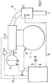
- An internal combustion engine 1 used in a motor vehicle has an intake system 2 and an injection system 4 for fuel acting on intake pipes 3. Ignition shorts 5 are used to ignite the supplied air / fuel mixture, and the corresponding exhaust gas is discharged via an exhaust line 6, which has an exhaust gas catalytic converter 7.
- An electronic control unit 8 is connected via signal-carrying lines 9 to an angle sensor 10 for detecting the throttle valve angle DW as a load signal L, to a speed sensor 11 for detecting the engine speed N, to the injection system 4, the spark plugs 5 and a temperature sensor 12 for detecting the exhaust gas temperature T. .
- the control unit 8 continuously records values of the parameters throttle valve angle DW and speed N detected by the sensors 10 and 11. Do these values suffice during a first time period t12 of e.g. Load, speed and temperature collectives determined in the control device 8 for 60 seconds, this control device 8 determines a first operating state B1 at the end of the time period t12 at a time t2. Internal combustion engine 1 and exhaust line 6 are now conditioned to continue the method.
- the operating state of the internal combustion engine changes by reducing the throttle valve angle DW to a value that corresponds to the overrun mode.
- a setpoint for this value is stored in control unit 8.
- the control unit 8 determines a coasting operation as the second operating state B2, during which the injection system 4 is switched off. The ignition of a cylinder of the internal combustion engine is then switched off for two revolutions of the crankshaft, during the second
- the injector of the injection system 4 assigned to this cylinder is activated by the control unit 8.
- a brief exhaust gas pulse is generated that does not correspond to regular overrun operation.
- the amount of fuel injected is supplied to the exhaust gas catalytic converter 7 together with the exhaust gas from the other, regularly operated cylinders and causes an exothermic reaction on its catalytic surface.
- the temperature sensor 12 detects an increased value for the exhaust gas temperature T.
- the time course of this temperature T is shown in FIG. 2 in the form of a diagram, on the abscissa the time t and on the ordinate the exhaust gas temperature T detected by the sensor 12 is plotted.
- a first curve K1 shows the temperature curve downstream of a functional exhaust gas catalytic converter 7 with short-term additional injection of fuel, while a second curve K2 shows this curve without additional injection.
- the almost identical course during the first time period t12 until the first operating state B1 is ascertained is clearly visible. Then follows the second time period t23 with a temperature increase DT with additional injection compared to curve K2.
- a third curve K3 shows the temperature profile of an exhaust gas catalytic converter with an already severely impaired conversion rate with additional injection. Despite this additional injection, the course of the curve is similar to that of curve K2, but due to the poor conversion rate it has shifted significantly to lower temperatures and is largely identical to a course without additional injection. A usable signal difference cannot be obtained.
- a first parameter difference DP1 is formed from the value of the engine speed N while the exhaust gas catalytic converter 7 is subjected to the exhaust gas pulse and its value after this application.
- control unit 8 determines control unit 8 whether DP1 is within DPS1. If this is the case, the process is continued with an evaluation, otherwise it is terminated. For the evaluation, the change in the exhaust gas temperature T recorded as the first parameter is compared with a target change stored in the control unit 8.
- this state is stored in a fault memory of the control unit 8 and a signal lamp 13 is actuated.
- the number of crankshaft revolutions during which the ignition is blanked out or additionally injected is changed in order to achieve reliable results, as a result of which the injection quantity is varied.
- a quick evaluation is achieved by comparing the value of T after the exhaust gas pulse with a predetermined target value and then comparing the change determined in this way with a target change range.
- the value of the exhaust gas temperature T can also be recorded and stored after the second operating state B2 has been identified.
- a second parameter difference DP2 is formed from this value and the value arising as a result of the exhaust gas pulse and compared with a predetermined, second target difference range DPS2.
Landscapes
- Engineering & Computer Science (AREA)
- Chemical & Material Sciences (AREA)
- Chemical Kinetics & Catalysis (AREA)
- Combustion & Propulsion (AREA)
- Mechanical Engineering (AREA)
- General Engineering & Computer Science (AREA)
- Exhaust Gas After Treatment (AREA)
- Electrical Control Of Air Or Fuel Supplied To Internal-Combustion Engine (AREA)
- Testing Of Engines (AREA)
Applications Claiming Priority (2)
| Application Number | Priority Date | Filing Date | Title |
|---|---|---|---|
| DE4302779A DE4302779C2 (de) | 1993-02-02 | 1993-02-02 | Verfahren zur Überprüfung der Funktionstüchtigkeit von im Abgasstrang, von mit einer Brennkraftmaschine ausgerüsteten Kraftfahrzeugen eingesetzten Abgaskatalysatoren |
| DE4302779 | 1993-02-02 |
Publications (2)
| Publication Number | Publication Date |
|---|---|
| EP0609527A1 true EP0609527A1 (fr) | 1994-08-10 |
| EP0609527B1 EP0609527B1 (fr) | 1998-02-25 |
Family
ID=6479375
Family Applications (1)
| Application Number | Title | Priority Date | Filing Date |
|---|---|---|---|
| EP93120014A Expired - Lifetime EP0609527B1 (fr) | 1993-02-02 | 1993-12-11 | Méthode pour examiner le bon fonctionnement des catalyseurs d'échappement |
Country Status (5)
| Country | Link |
|---|---|
| US (1) | US5435172A (fr) |
| EP (1) | EP0609527B1 (fr) |
| JP (1) | JPH0771233A (fr) |
| KR (1) | KR100270151B1 (fr) |
| DE (2) | DE4302779C2 (fr) |
Cited By (7)
| Publication number | Priority date | Publication date | Assignee | Title |
|---|---|---|---|---|
| WO1996016257A1 (fr) | 1994-11-22 | 1996-05-30 | Roth-Technik Gmbh & Co. Forschung Für Automobil- Und Umwelttechnik | Dispositif utilise pour surveiller l'aptitude au fonctionnement de catalyseurs et/ou de sondes lambda |
| WO1999028603A3 (fr) * | 1997-11-30 | 1999-08-19 | Wissenschaftliche Werkstatt Fu | Mesure de constituants de substances nocives contenues dans des gaz d'echappement et reduction d'emissions de substances nocives au cours du demarrage a froid et du trajet |
| WO2001049989A1 (fr) * | 1999-12-31 | 2001-07-12 | Robert Bosch Gmbh | Procede pour faire fonctionner un moteur a combustion interne, notamment d'un vehicule automobile |
| EP1052385A3 (fr) * | 1999-04-29 | 2001-10-17 | Siemens Aktiengesellschaft | Procédé pour établir un diagnostic d'un catalyseur ayant des caractéristiques d'oxydation des carbures d'hydrogène |
| US7082752B2 (en) | 2001-03-17 | 2006-08-01 | Robert Bosch Gmbh | Method and device for monitoring an exhaust gas treatment system |
| EP1247007B1 (fr) * | 1999-12-31 | 2007-01-17 | Robert Bosch Gmbh | Procede de diagnostique d'un catalyseur d'un moteur a combustion interne |
| US8443589B2 (en) | 2004-06-18 | 2013-05-21 | GM Global Technology Operations LLC | Diesel oxidation catalyst efficiency diagnostic method |
Families Citing this family (20)
| Publication number | Priority date | Publication date | Assignee | Title |
|---|---|---|---|---|
| DE59404052D1 (de) * | 1993-12-21 | 1997-10-16 | Siemens Ag | Verfahren zur überprüfung der konvertierungsfähigkeit eines katalysators |
| DE4440276C2 (de) * | 1994-11-11 | 1996-09-05 | Volkswagen Ag | Verfahren zur Überwachung des Konvertierungsgrades eines Abgaskatalysators |
| JP3239698B2 (ja) * | 1995-07-25 | 2001-12-17 | トヨタ自動車株式会社 | 内燃機関の触媒劣化判定装置 |
| JP3316137B2 (ja) * | 1996-07-26 | 2002-08-19 | 株式会社日立製作所 | エンジンの排気浄化装置 |
| JP3267188B2 (ja) * | 1997-05-12 | 2002-03-18 | トヨタ自動車株式会社 | 内燃機関の触媒劣化判定装置 |
| EP0908721A1 (fr) * | 1997-10-10 | 1999-04-14 | Heraeus Electro-Nite International N.V. | Procédé pour determiner la température de gaz d'échappement et le rapport air/carburant lambda et dispositif pour la mise en oeuvre de ce procédé |
| DE19806110C2 (de) * | 1997-10-10 | 2001-01-04 | Heraeus Electro Nite Int | Verfahren zur Ermittlung der Abgastemperatur und der Luft/Kraftstoff-Verhältniszahl Lambda und Sensoranordnung zur Durchführung des Verfahrens |
| US6076660A (en) | 1998-02-05 | 2000-06-20 | Sulzer Calcitek Inc. | Vial for dental implant delivery system |
| US6651422B1 (en) | 1998-08-24 | 2003-11-25 | Legare Joseph E. | Catalyst efficiency detection and heating method using cyclic fuel control |
| US7886523B1 (en) | 1998-08-24 | 2011-02-15 | Legare Joseph E | Control methods for improved catalytic converter efficiency and diagnosis |
| US7707821B1 (en) * | 1998-08-24 | 2010-05-04 | Legare Joseph E | Control methods for improved catalytic converter efficiency and diagnosis |
| DE19946628A1 (de) * | 1999-09-29 | 2001-04-05 | Volkswagen Ag | Verfahren zur Diagnose eines Schädigungszustandes eines in einem Abgaskanal einer Verbrennungskraftmaschine angeordneten NOx-Speicherkatalysators |
| DE19955972C2 (de) * | 1999-11-19 | 2002-03-14 | Heraeus Electro Nite Int | Verfahren zum Kalibrieren eines Temperatursensors |
| DE19955947C2 (de) * | 1999-11-19 | 2002-04-11 | Heraeus Electro Nite Int | Verfahren zur Überprüfung der katalytischen Aktivität eines Katalysators |
| JP2001304032A (ja) * | 2000-04-27 | 2001-10-31 | Toyota Motor Corp | 触媒劣化検出装置 |
| DE10254477B3 (de) * | 2002-11-21 | 2004-06-24 | Siemens Ag | Prüfverfahren für einen Abgaskatalysator und eine entsprechende Prüfeinrichtung |
| US6983589B2 (en) * | 2003-05-07 | 2006-01-10 | Ford Global Technologies, Llc | Diesel aftertreatment systems |
| DE102005040906A1 (de) * | 2005-08-30 | 2007-03-08 | Daimlerchrysler Ag | Verfahren zur Überwachung eines Abgasreinigungsbauteils |
| DE102009056026B4 (de) * | 2009-11-27 | 2018-01-11 | Audi Ag | Verfahren zum Betreiben einer Brennkraftmaschine eines Kraftfahrzeugs |
| AT519529B1 (de) * | 2016-12-22 | 2019-04-15 | Avl List Gmbh | Verfahren zur überwachung eines abgasnachbehandlungsbauteils |
Citations (3)
| Publication number | Priority date | Publication date | Assignee | Title |
|---|---|---|---|---|
| DE3811732A1 (de) * | 1988-04-08 | 1989-10-19 | Deutsche Fernsprecher Gmbh | Schaltungsanorndnung zur funktionspruefung des katalysators von kraftfahrzeugen |
| EP0442648A2 (fr) * | 1990-02-14 | 1991-08-21 | Lucas Industries Public Limited Company | Procédé et appareil pour contrôler le fonctionnement d'un converteur catalytique |
| US5060473A (en) * | 1988-07-13 | 1991-10-29 | Nissan Motor Company, Limited | System for detecting deterioration of catalyst in catalytic converter |
Family Cites Families (14)
| Publication number | Priority date | Publication date | Assignee | Title |
|---|---|---|---|---|
| SE403835B (sv) * | 1977-01-13 | 1978-09-04 | Collin Consult Ab Lars | Forfaringssett och anordning for att vid analys av avgaser fran fordonsmotorer erhalla verden som er jemforbart representativa for olika motorer |
| JPS5566317A (en) * | 1978-11-14 | 1980-05-19 | Matsushita Electric Industrial Co Ltd | Kitchen furniture |
| JPS55162613U (fr) * | 1979-05-12 | 1980-11-21 | ||
| JPS58224745A (ja) * | 1982-06-23 | 1983-12-27 | 三菱化成ポリテック株式会社 | 事務用品収納用袋状容器 |
| JPS59224745A (ja) * | 1983-06-01 | 1984-12-17 | 株式会社日本アルミ | 建物の伸縮継手装置 |
| DE3516981A1 (de) * | 1985-05-10 | 1986-11-13 | Audi AG, 8070 Ingolstadt | Verfahren zum ueberpruefen der funktionsfaehigkeit eines abgaskatalysators |
| DE3736259C2 (de) * | 1986-11-07 | 1998-01-29 | Volkswagen Ag | Einrichtung zur Ermittlung des Konvertierungsgrads eines Katalysators |
| DE3935381A1 (de) * | 1988-10-28 | 1990-05-03 | Volkswagen Ag | Verfahren und einrichtung zur ueberpruefung der funktionsfaehigkeit eines abgaskatalysators |
| US5133184A (en) * | 1990-02-10 | 1992-07-28 | Volkswagen Ag | Method and apparatus for monitoring the conversion ratio of a catalytic converter |
| DE4100397C2 (de) * | 1990-02-10 | 1999-08-05 | Volkswagen Ag | Verfahren und Anordnung zur Überwachung des Konvertierungsgrads eines Katalysators |
| JPH0417141U (fr) * | 1990-05-30 | 1992-02-13 | ||
| JPH0460106A (ja) * | 1990-06-29 | 1992-02-26 | Mazda Motor Corp | エンジンの制御装置 |
| DE4027207A1 (de) * | 1990-08-28 | 1992-03-05 | Emitec Emissionstechnologie | Ueberwachung der katalytischen aktivitaet eines katalysators im abgassystem einer brennkraftmaschine |
| US5265416A (en) * | 1992-08-27 | 1993-11-30 | Ford Motor Company | On-board catalytic converter efficiency monitoring |
-
1993
- 1993-02-02 DE DE4302779A patent/DE4302779C2/de not_active Expired - Fee Related
- 1993-12-11 EP EP93120014A patent/EP0609527B1/fr not_active Expired - Lifetime
- 1993-12-11 DE DE59308177T patent/DE59308177D1/de not_active Expired - Fee Related
-
1994
- 1994-02-01 KR KR1019940001806A patent/KR100270151B1/ko not_active Expired - Fee Related
- 1994-02-01 JP JP6010667A patent/JPH0771233A/ja not_active Withdrawn
- 1994-02-02 US US08/190,370 patent/US5435172A/en not_active Expired - Fee Related
Patent Citations (3)
| Publication number | Priority date | Publication date | Assignee | Title |
|---|---|---|---|---|
| DE3811732A1 (de) * | 1988-04-08 | 1989-10-19 | Deutsche Fernsprecher Gmbh | Schaltungsanorndnung zur funktionspruefung des katalysators von kraftfahrzeugen |
| US5060473A (en) * | 1988-07-13 | 1991-10-29 | Nissan Motor Company, Limited | System for detecting deterioration of catalyst in catalytic converter |
| EP0442648A2 (fr) * | 1990-02-14 | 1991-08-21 | Lucas Industries Public Limited Company | Procédé et appareil pour contrôler le fonctionnement d'un converteur catalytique |
Cited By (11)
| Publication number | Priority date | Publication date | Assignee | Title |
|---|---|---|---|---|
| WO1996016257A1 (fr) | 1994-11-22 | 1996-05-30 | Roth-Technik Gmbh & Co. Forschung Für Automobil- Und Umwelttechnik | Dispositif utilise pour surveiller l'aptitude au fonctionnement de catalyseurs et/ou de sondes lambda |
| EP0793770B1 (fr) * | 1994-11-22 | 2000-07-19 | Heraeus Electro-Nite International N.V. | Dispositif utilise pour surveiller l'aptitude au fonctionnement de catalyseurs |
| WO1999028603A3 (fr) * | 1997-11-30 | 1999-08-19 | Wissenschaftliche Werkstatt Fu | Mesure de constituants de substances nocives contenues dans des gaz d'echappement et reduction d'emissions de substances nocives au cours du demarrage a froid et du trajet |
| AU755619B2 (en) * | 1997-11-30 | 2002-12-19 | Wissenschaftliche Werkstatt Fur Umweltmesstechnik Gmbh | Measurement of contaminant components in exhaust gas and reduction of excessive contaminant emissions during cold starts and while driving |
| US6532793B1 (en) | 1997-11-30 | 2003-03-18 | Wissenschaftliche Werkstatt Fur Umweltmesstechnik Gmbh | Measurement of contaminant components in exhaust gas and reduction of excessive contaminant emissions during cold starts and while driving |
| EP1052385A3 (fr) * | 1999-04-29 | 2001-10-17 | Siemens Aktiengesellschaft | Procédé pour établir un diagnostic d'un catalyseur ayant des caractéristiques d'oxydation des carbures d'hydrogène |
| WO2001049989A1 (fr) * | 1999-12-31 | 2001-07-12 | Robert Bosch Gmbh | Procede pour faire fonctionner un moteur a combustion interne, notamment d'un vehicule automobile |
| EP1247007B1 (fr) * | 1999-12-31 | 2007-01-17 | Robert Bosch Gmbh | Procede de diagnostique d'un catalyseur d'un moteur a combustion interne |
| US7082752B2 (en) | 2001-03-17 | 2006-08-01 | Robert Bosch Gmbh | Method and device for monitoring an exhaust gas treatment system |
| US8443589B2 (en) | 2004-06-18 | 2013-05-21 | GM Global Technology Operations LLC | Diesel oxidation catalyst efficiency diagnostic method |
| DE102005027686B4 (de) * | 2004-06-18 | 2013-08-14 | General Motors Corp. | Diagnoseverfahren für den Wirkungsgrad eines Diesel-Oxidationskatalysators |
Also Published As
| Publication number | Publication date |
|---|---|
| DE4302779A1 (de) | 1994-08-04 |
| KR100270151B1 (ko) | 2001-03-02 |
| DE59308177D1 (de) | 1998-04-02 |
| DE4302779C2 (de) | 1995-10-05 |
| EP0609527B1 (fr) | 1998-02-25 |
| US5435172A (en) | 1995-07-25 |
| JPH0771233A (ja) | 1995-03-14 |
Similar Documents
| Publication | Publication Date | Title |
|---|---|---|
| DE4302779C2 (de) | Verfahren zur Überprüfung der Funktionstüchtigkeit von im Abgasstrang, von mit einer Brennkraftmaschine ausgerüsteten Kraftfahrzeugen eingesetzten Abgaskatalysatoren | |
| DE60003105T2 (de) | Vorrichtung zur Abgasemissionssteuerung einer Brennkraftmaschine | |
| DE2845043C2 (de) | Regelsystem für Brennkraftmaschinen | |
| EP1426575B1 (fr) | Procédé et dispositif de surveillance d'un système de traitement des gaz d'échappement | |
| DE102008001569A1 (de) | Verfahren und Vorrichtung zur Adaption eines Dynamikmodells einer Abgassonde | |
| DE4337793C2 (de) | Verfahren und Vorrichtung zum Beurteilen des Funktionszustandes eines Katalysators | |
| DE19859462B4 (de) | Verfahren zur Entgiftung eines Katalysators sowie Motorsteuersystem zur Durchführung des Katalysatorentgiftungsverfahrens | |
| EP1097299A1 (fr) | PROCEDE DE VERIFICATION DU RENDEMENT D'UN POT CATALYTIQUE A ACCUMULATION DE NOx | |
| DE19809173A1 (de) | Verfahren und Vorrichtung zum Steuern der Kraftstoffeinspritzung | |
| DE3634873A1 (de) | Verfahren zum bestimmen der eignung eines abgaskonzentrationssensors | |
| DE19545924B4 (de) | Verfahren und Vorrichtungen zum Steuern des Luft/Kraftstoffverhältnis-Lernens eines Motors mit innerer Verbrennung | |
| DE102018102867A1 (de) | Abnormitätsdiagnosevorrichtung für Verbrennungskraftmaschine und Abnormitätsdiagnoseverfahren für Verbrennungskraftmaschine | |
| DE4435196C1 (de) | Verfahren zum Überprüfen eines Brennersystems zur Katalysatoraufheizung | |
| WO2009062787A1 (fr) | Détermination de la qualité du carburant pour un moteur à combustion interne à auto-allumage | |
| DE102009045376A1 (de) | Verfahren und Vorrichtung zur Diagnose der Dynamik eines Abgassensors | |
| DE4309854A1 (de) | Verfahren und Vorrichtung zur Steuerung der Sekundärluftzufuhr für eine Brennkraftmaschine | |
| DE4134522A1 (de) | Einrichtung und verfahren zur elektronischen kraftstoffeinspritzsteuerung fuer verbrennungsmotor | |
| DE102004051747A1 (de) | Verfahren zum Betreiben einer Brennkraftmaschine und Vorrichtung zur Durchführung des Verfahrens | |
| DE102009054935B4 (de) | Verfahren und Vorrichtung zur Diagnose der Dynamik eines Abgassensors | |
| DE10310954A1 (de) | Verfahren zur Diagnose eines NOx-Sensors | |
| EP1247966A2 (fr) | Méthode pour détecter la permutation de sondes à oxygène | |
| DE19801629B4 (de) | Katalysatordiagnoseverfahren und Vorrichtung | |
| DE19609922B4 (de) | Sekundärluftsystemdiagnoseverfahren | |
| WO2009040293A1 (fr) | Procédé et dispositif pour déterminer une propriété dynamique d'une sonde de richesse des gaz d'échappement | |
| DE10338664A1 (de) | Verfahren zum Betreiben einer Brennkraftmaschine eines Fahrzeuges, insbesondere eines Kraftfahrzeuges sowie Vorrichtung zur Durchführung eines derartigen Verfahrens |
Legal Events
| Date | Code | Title | Description |
|---|---|---|---|
| PUAI | Public reference made under article 153(3) epc to a published international application that has entered the european phase |
Free format text: ORIGINAL CODE: 0009012 |
|
| AK | Designated contracting states |
Kind code of ref document: A1 Designated state(s): DE FR GB IT |
|
| 17P | Request for examination filed |
Effective date: 19950118 |
|
| 17Q | First examination report despatched |
Effective date: 19950412 |
|
| GRAG | Despatch of communication of intention to grant |
Free format text: ORIGINAL CODE: EPIDOS AGRA |
|
| GRAG | Despatch of communication of intention to grant |
Free format text: ORIGINAL CODE: EPIDOS AGRA |
|
| GRAH | Despatch of communication of intention to grant a patent |
Free format text: ORIGINAL CODE: EPIDOS IGRA |
|
| ITF | It: translation for a ep patent filed | ||
| GRAH | Despatch of communication of intention to grant a patent |
Free format text: ORIGINAL CODE: EPIDOS IGRA |
|
| GRAA | (expected) grant |
Free format text: ORIGINAL CODE: 0009210 |
|
| AK | Designated contracting states |
Kind code of ref document: B1 Designated state(s): DE FR GB IT |
|
| REF | Corresponds to: |
Ref document number: 59308177 Country of ref document: DE Date of ref document: 19980402 |
|
| ET | Fr: translation filed | ||
| GBT | Gb: translation of ep patent filed (gb section 77(6)(a)/1977) |
Effective date: 19980406 |
|
| PLBE | No opposition filed within time limit |
Free format text: ORIGINAL CODE: 0009261 |
|
| STAA | Information on the status of an ep patent application or granted ep patent |
Free format text: STATUS: NO OPPOSITION FILED WITHIN TIME LIMIT |
|
| 26N | No opposition filed | ||
| PGFP | Annual fee paid to national office [announced via postgrant information from national office to epo] |
Ref country code: GB Payment date: 19991208 Year of fee payment: 7 |
|
| PGFP | Annual fee paid to national office [announced via postgrant information from national office to epo] |
Ref country code: FR Payment date: 20000128 Year of fee payment: 7 |
|
| PG25 | Lapsed in a contracting state [announced via postgrant information from national office to epo] |
Ref country code: GB Free format text: LAPSE BECAUSE OF NON-PAYMENT OF DUE FEES Effective date: 20001211 |
|
| GBPC | Gb: european patent ceased through non-payment of renewal fee |
Effective date: 20001211 |
|
| PG25 | Lapsed in a contracting state [announced via postgrant information from national office to epo] |
Ref country code: FR Free format text: LAPSE BECAUSE OF NON-PAYMENT OF DUE FEES Effective date: 20010831 |
|
| REG | Reference to a national code |
Ref country code: FR Ref legal event code: ST |
|
| PGFP | Annual fee paid to national office [announced via postgrant information from national office to epo] |
Ref country code: DE Payment date: 20041201 Year of fee payment: 12 |
|
| PG25 | Lapsed in a contracting state [announced via postgrant information from national office to epo] |
Ref country code: IT Free format text: LAPSE BECAUSE OF NON-PAYMENT OF DUE FEES Effective date: 20051211 |
|
| PG25 | Lapsed in a contracting state [announced via postgrant information from national office to epo] |
Ref country code: DE Free format text: LAPSE BECAUSE OF NON-PAYMENT OF DUE FEES Effective date: 20060701 |