EP0609545A1 - Elément de construction pour l'isolation thermique - Google Patents
Elément de construction pour l'isolation thermique Download PDFInfo
- Publication number
- EP0609545A1 EP0609545A1 EP93120510A EP93120510A EP0609545A1 EP 0609545 A1 EP0609545 A1 EP 0609545A1 EP 93120510 A EP93120510 A EP 93120510A EP 93120510 A EP93120510 A EP 93120510A EP 0609545 A1 EP0609545 A1 EP 0609545A1
- Authority
- EP
- European Patent Office
- Prior art keywords
- insulating body
- bars
- approximately
- component according
- loop
- Prior art date
- Legal status (The legal status is an assumption and is not a legal conclusion. Google has not performed a legal analysis and makes no representation as to the accuracy of the status listed.)
- Granted
Links
- 238000009413 insulation Methods 0.000 title claims abstract description 4
- 238000010276 construction Methods 0.000 title abstract description 7
- 230000002787 reinforcement Effects 0.000 claims description 8
- 229910001220 stainless steel Inorganic materials 0.000 claims description 2
- 239000010935 stainless steel Substances 0.000 claims description 2
- 230000007704 transition Effects 0.000 claims description 2
- 229910000831 Steel Inorganic materials 0.000 claims 1
- 239000010959 steel Substances 0.000 claims 1
- 230000006835 compression Effects 0.000 abstract description 4
- 238000007906 compression Methods 0.000 abstract description 4
- 238000004519 manufacturing process Methods 0.000 description 3
- 230000003014 reinforcing effect Effects 0.000 description 2
- QVGXLLKOCUKJST-UHFFFAOYSA-N atomic oxygen Chemical compound [O] QVGXLLKOCUKJST-UHFFFAOYSA-N 0.000 description 1
- 238000005452 bending Methods 0.000 description 1
- 238000005260 corrosion Methods 0.000 description 1
- 230000007797 corrosion Effects 0.000 description 1
- 230000001419 dependent effect Effects 0.000 description 1
- 238000009792 diffusion process Methods 0.000 description 1
- 239000000463 material Substances 0.000 description 1
- 230000007935 neutral effect Effects 0.000 description 1
- 229910052760 oxygen Inorganic materials 0.000 description 1
- 239000001301 oxygen Substances 0.000 description 1
- 125000006850 spacer group Chemical group 0.000 description 1
Images
Classifications
-
- E—FIXED CONSTRUCTIONS
- E04—BUILDING
- E04B—GENERAL BUILDING CONSTRUCTIONS; WALLS, e.g. PARTITIONS; ROOFS; FLOORS; CEILINGS; INSULATION OR OTHER PROTECTION OF BUILDINGS
- E04B1/00—Constructions in general; Structures which are not restricted either to walls, e.g. partitions, or floors or ceilings or roofs
- E04B1/003—Balconies; Decks
- E04B1/0038—Anchoring devices specially adapted therefor with means for preventing cold bridging
Definitions
- the invention relates to a component for thermal insulation between two components to be concreted, in particular between a building and a cantilevered outer part, consisting of an insulating body to be laid between them with integrated metallic tensile, compressive and transverse force rods which extend transversely to the insulating body and through it protrude on both sides into the components to be concreted, the transverse force rods starting from the building side running obliquely from top to bottom through the insulating body and then protruding in the area of the pressure zone in the direction of the projecting outer part to be concreted.
- each insulating body is equipped with a plurality of horizontally continuous tension and compression bars and with obliquely installed transverse force bars, the number of reinforcing bars depending on the length of the insulating body and that between the subsequent ones Concrete parts is dependent on transmitted forces.
- the tension, compression and shear bars protrude horizontally from the insulating body, which ensures coverage with the connecting reinforcement of the components that connect on both sides.
- the present invention seeks to improve the component, in particular to improve its stability. In addition, the assembly and manufacturing costs are to be reduced.
- transverse force bars arranged in the vicinity of the pressure bars converge again with the start of the loop in the area of the projecting outer part to be concreted, forming an approximately vertical loop which extends upwards and is approximately perpendicular to the insulating body and in the loop area of the Shear force bars at the level of the pressure bars, a cross-directional distribution bar for edge reinforcement is fixed, in particular welded.
- the distributor rod integrated according to the invention allows the position of the construction site reinforcement for the outer part to be fixed, because the plug-in stirrups at the end, which hold the tension and the pressure-absorbing Connect reinforcement elements, can be placed on the distributor bar in a simple manner, so that the spacers previously required for height fixing can be omitted.
- the function of the stirrups can be taken over by the loops mentioned.
- the preassembly of the distributor bar simplifies the production process, since assembly on the construction site is generally associated with greater effort. Pre-assembly also eliminates the risk of forgetting to assemble the distribution bar.
- the distributor rod is preferably welded both to the transverse force rods and to the pressure rods. This results in an optimal positional fixation of the pressure rods and the transverse force rods relative to the insulating body.
- the positions of the pressure rods or their pressure bearings on the one hand and the shear force rods on the other hand must be coordinated so that the distributor rod rests on the two reinforcement elements mentioned.
- the thrust bearing can also be used to fasten the distributor rod and / or the transverse force rods, for example by arranging the distributor rod on the rear side facing the insulating body or on the front side of the thrust bearing.
- the loop is designed approximately in the form of a flat rectangle, the narrow side lying away from the insulating body also being approximately semicircular, and the lower and upper loop parts running approximately horizontally, namely the lower part approximately at the height of the pressure rods and upper part approximately in the train area. Accordingly, the beginning and end of the loop converge at an angle of approximately 90 ° at a certain distance from the insulating body and are welded there.
- the pressure rods are expediently provided at both ends with cross-sectional expansions in the form of plate-like thrust bearings, as a result of which the pressure forces to be transmitted are distributed over a larger contact surface on the concrete components at the joints. This reduces the Hertzian pressure that occurs.
- the shear bars from stainless steel, at least within the insulating body and in the transition area adjacent on both sides.
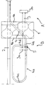
- the component consists of an essentially rectangular insulating body 1, which is arranged on the construction site between the concrete slabs to be concreted. It has a series of tension rods 2 in its upper region and a series of compression rods 3 in its lower region. While the pressure bars do not protrude very far on both sides, the tension bars protrude far into the components to be concreted.
- the insulating body 1 carries a series of shear bars 4, which serve in the usual way to absorb the vertical weight of the projecting outer part.
- shear bars 4 serve in the usual way to absorb the vertical weight of the projecting outer part.
- the protruding part of the transverse force rod 4 assigned to the outer part B is extended to form a loop 4a, namely proceeding approximately horizontally from the beginning of its loop 4b, extending upwards in the form of a semicircle 4c, from there again approximately horizontally in the direction of Insulating body 1 runs back to run downward approximately above the pressure rod ends so that its end 4d forms an angle of approximately 90 ° with the beginning 4b of the loop described in this way at its crossing point.
- the pressure rod which is designed as a plate-shaped thrust bearing 3a, and the loop end 4d of the transverse force rod 4
- a horizontal distributor rod 5 running parallel to the insulating body 1. It is welded to the pressure rods 3 or their thrust bearing 3a as well as to the lower loop parts 4b of the shear force rods 4 and serves on the one hand as a support for the construction site reinforcement of the outer part to be concreted, and on the other hand for fixing the shear force rods 4 and pressure rods 3 relative to the insulating body.
Landscapes
- Engineering & Computer Science (AREA)
- Architecture (AREA)
- Physics & Mathematics (AREA)
- Electromagnetism (AREA)
- Civil Engineering (AREA)
- Structural Engineering (AREA)
- Reinforcement Elements For Buildings (AREA)
- Building Environments (AREA)
- Insulated Conductors (AREA)
- Macromolecular Compounds Obtained By Forming Nitrogen-Containing Linkages In General (AREA)
Applications Claiming Priority (2)
| Application Number | Priority Date | Filing Date | Title |
|---|---|---|---|
| DE4302682A DE4302682A1 (de) | 1993-02-01 | 1993-02-01 | Bauelement zur Wärmedämmung |
| DE4302682 | 1993-02-01 |
Publications (2)
| Publication Number | Publication Date |
|---|---|
| EP0609545A1 true EP0609545A1 (fr) | 1994-08-10 |
| EP0609545B1 EP0609545B1 (fr) | 1996-09-18 |
Family
ID=6479320
Family Applications (1)
| Application Number | Title | Priority Date | Filing Date |
|---|---|---|---|
| EP93120510A Expired - Lifetime EP0609545B1 (fr) | 1993-02-01 | 1993-12-20 | Elément de construction pour l'isolation thermique |
Country Status (4)
| Country | Link |
|---|---|
| EP (1) | EP0609545B1 (fr) |
| AT (1) | ATE143081T1 (fr) |
| DE (2) | DE4302682A1 (fr) |
| DK (1) | DK0609545T3 (fr) |
Cited By (5)
| Publication number | Priority date | Publication date | Assignee | Title |
|---|---|---|---|---|
| EP1754840A3 (fr) * | 2005-08-18 | 2007-05-16 | SCHÖCK BAUTEILE GmbH | Elément de construction pour l'isolation thermique |
| EP2055845A2 (fr) | 2007-11-02 | 2009-05-06 | Debrunner Koenig Management AG | Elément de montage de dalles en porte-à-faux |
| US7823352B2 (en) | 2005-08-18 | 2010-11-02 | Schöck Bauteile GmbH | Construction element for heat insulation |
| EP3569779A1 (fr) | 2018-05-18 | 2019-11-20 | Schöck Bauteile GmbH | Composant permettant le raccordement à pont thermique faible d'une partie extérieure en saillie à une enveloppe de bâtiment |
| EP3569778A1 (fr) | 2018-05-18 | 2019-11-20 | Schöck Bauteile GmbH | Procédé de fabrication d'un composant, ainsi que composant permettant le raccordement à pont thermique faible d'une partie extérieure en saillie à une enveloppe de bâtiment |
Families Citing this family (10)
| Publication number | Priority date | Publication date | Assignee | Title |
|---|---|---|---|---|
| DE4342673A1 (de) * | 1993-12-15 | 1995-06-22 | Schoeck Bauteile Gmbh | Bauelement zur Wärmedämmung |
| AT964U1 (de) * | 1994-10-31 | 1996-08-26 | Hako Bautechnik Ges M B H | Wärmedämmendes anschlussstück |
| DE19528130B4 (de) * | 1995-06-24 | 2005-07-21 | Schöck Bauteile GmbH | Bauelement zur Wärmedämmung |
| DE19623298C2 (de) * | 1996-05-23 | 2000-11-16 | Richard Moosmann | Verbindungselement |
| DE19638538A1 (de) * | 1996-09-20 | 1998-03-26 | Schoeck Bauteile Gmbh | Bauelement zur Wärmedämmung |
| DE19640652A1 (de) * | 1996-10-02 | 1998-04-09 | Schoeck Bauteile Gmbh | Bauelement zur Wärmedämmung |
| DE19711187A1 (de) * | 1997-03-18 | 1998-09-24 | Schoeck Bauteile Gmbh | System zur Wärmedämmung |
| DE19804038A1 (de) * | 1998-02-03 | 1999-08-05 | Schoeck Bauteile Gmbh | Bauelement zur Wärmedämmung |
| DE102010027661B4 (de) | 2010-07-19 | 2012-08-02 | Schöck Bauteile GmbH | Schalungsvorrichtung und Verfahren zum Schaffen einer Aussparung beim Gießen eines Gebäudebauteils |
| DE202016103344U1 (de) * | 2016-06-23 | 2016-08-01 | Max Frank Gmbh & Co. Kg | Anschlusselement für lasteinleitende Bauteile |
Citations (2)
| Publication number | Priority date | Publication date | Assignee | Title |
|---|---|---|---|---|
| CH677249A5 (en) * | 1987-03-11 | 1991-04-30 | Avi Alpenlaendische Vered | Bridging grid for structural beams - is of rod construction, with short, bent spacer welded between upper and lower horizontals |
| DE4033505A1 (de) * | 1990-10-20 | 1992-04-23 | Schoeck Bauteile Gmbh | Bauelement zur waermedaemmung bei gebaeuden |
Family Cites Families (4)
| Publication number | Priority date | Publication date | Assignee | Title |
|---|---|---|---|---|
| CH652160A5 (de) * | 1983-03-11 | 1985-10-31 | Walter Egger | Kragplattenanschlusselement. |
| DE3422905A1 (de) * | 1984-06-20 | 1986-01-02 | Hansjörg Dipl.-Ing. 7542 Schömberg Braun | Vorrichtung zum verbinden einer balkonplatte und einer geschossdecke |
| DE3739967A1 (de) * | 1987-11-25 | 1989-06-08 | Meisinger Kg M | Stahltraeger fuer eine beton-kragplatte |
| DE9014573U1 (de) * | 1990-10-20 | 1991-02-21 | Schöck Bauteile GmbH, 7570 Baden-Baden | Bauelement zur Wärmedämmung bei Gebäuden |
-
1993
- 1993-02-01 DE DE4302682A patent/DE4302682A1/de not_active Withdrawn
- 1993-12-20 DE DE59303876T patent/DE59303876D1/de not_active Expired - Lifetime
- 1993-12-20 DK DK93120510.8T patent/DK0609545T3/da active
- 1993-12-20 AT AT93120510T patent/ATE143081T1/de active
- 1993-12-20 EP EP93120510A patent/EP0609545B1/fr not_active Expired - Lifetime
Patent Citations (2)
| Publication number | Priority date | Publication date | Assignee | Title |
|---|---|---|---|---|
| CH677249A5 (en) * | 1987-03-11 | 1991-04-30 | Avi Alpenlaendische Vered | Bridging grid for structural beams - is of rod construction, with short, bent spacer welded between upper and lower horizontals |
| DE4033505A1 (de) * | 1990-10-20 | 1992-04-23 | Schoeck Bauteile Gmbh | Bauelement zur waermedaemmung bei gebaeuden |
Cited By (5)
| Publication number | Priority date | Publication date | Assignee | Title |
|---|---|---|---|---|
| EP1754840A3 (fr) * | 2005-08-18 | 2007-05-16 | SCHÖCK BAUTEILE GmbH | Elément de construction pour l'isolation thermique |
| US7823352B2 (en) | 2005-08-18 | 2010-11-02 | Schöck Bauteile GmbH | Construction element for heat insulation |
| EP2055845A2 (fr) | 2007-11-02 | 2009-05-06 | Debrunner Koenig Management AG | Elément de montage de dalles en porte-à-faux |
| EP3569779A1 (fr) | 2018-05-18 | 2019-11-20 | Schöck Bauteile GmbH | Composant permettant le raccordement à pont thermique faible d'une partie extérieure en saillie à une enveloppe de bâtiment |
| EP3569778A1 (fr) | 2018-05-18 | 2019-11-20 | Schöck Bauteile GmbH | Procédé de fabrication d'un composant, ainsi que composant permettant le raccordement à pont thermique faible d'une partie extérieure en saillie à une enveloppe de bâtiment |
Also Published As
| Publication number | Publication date |
|---|---|
| DE4302682A1 (de) | 1994-08-04 |
| DK0609545T3 (da) | 1996-10-07 |
| EP0609545B1 (fr) | 1996-09-18 |
| ATE143081T1 (de) | 1996-10-15 |
| DE59303876D1 (de) | 1996-10-24 |
Similar Documents
| Publication | Publication Date | Title |
|---|---|---|
| EP0609545B1 (fr) | Elément de construction pour l'isolation thermique | |
| EP0499590B1 (fr) | Elément connecteur isolant pour planchers de balcon et l'usage de cet élément | |
| EP4036338A1 (fr) | Dispositif de raccordement ultérieur à isolation thermique et à transfert de force d'une seconde partie d'ouvrage supportant la charge à une première partie d'ouvrage supportant la charge et ouvrage doté d'un tel dispositif | |
| DE3422905A1 (de) | Vorrichtung zum verbinden einer balkonplatte und einer geschossdecke | |
| DE2727159A1 (de) | Bewehrung von flachdecken gegen durchstanzen | |
| DE3700295C2 (de) | Bauelement zur Isolierung bei Gebäuden | |
| CH683545A5 (de) | Schubbewehrung für Flachdecken. | |
| CH678204A5 (fr) | ||
| EP0750076A1 (fr) | Elément de construction pour isolation thermique | |
| EP0605815B1 (fr) | Elément de construction pour l'isolation thermique de bâtiments | |
| DE19640652A1 (de) | Bauelement zur Wärmedämmung | |
| DE3318431C2 (de) | Deckenelement | |
| EP0609690B1 (fr) | Elément de construction pour l'isolation thermique de bâtiments | |
| CH690966A5 (de) | Isolierendes Anschlusselement für Kragplatten. | |
| DE10350082B4 (de) | Vorgespannte Flachdecke mit Hohldeckenplatten | |
| DE29903737U1 (de) | Bauelement zur Schubbewehrung | |
| EP2080841B1 (fr) | Elément de pose de dalles en console | |
| DE4002001A1 (de) | Anschlussverankerung zur abstuetzung mindestens eines vorkragenden bauwerkteiles sowie anschlusselement | |
| EP3617415B1 (fr) | Élément d'armature de poinçonnement et construction dotée d'une plaque dotée d'un élément d'armature de poinçonnement | |
| DE10001595A1 (de) | Bewehrung für Stahlbetondecken | |
| CH689231A5 (de) | Waermedaemmendes Kragplattenanschlusselement. | |
| EP4050170B1 (fr) | Construction pourvue d'élément thermoisolant | |
| DE3700429A1 (de) | Schalungsquerriegel aus stahl zum verbinden mehrerer schalungsplatten-traeger | |
| DE4228968A1 (de) | Balken, verfahren zu dessen herstellung, verfahren und vorrichtung zum verbinden solcher balken | |
| DE3410419A1 (de) | Schubbewehrungselement |
Legal Events
| Date | Code | Title | Description |
|---|---|---|---|
| PUAI | Public reference made under article 153(3) epc to a published international application that has entered the european phase |
Free format text: ORIGINAL CODE: 0009012 |
|
| 17P | Request for examination filed |
Effective date: 19940609 |
|
| AK | Designated contracting states |
Kind code of ref document: A1 Designated state(s): AT BE CH DE DK FR GB IT LI LU NL SE |
|
| 17Q | First examination report despatched |
Effective date: 19951120 |
|
| GRAH | Despatch of communication of intention to grant a patent |
Free format text: ORIGINAL CODE: EPIDOS IGRA |
|
| GRAH | Despatch of communication of intention to grant a patent |
Free format text: ORIGINAL CODE: EPIDOS IGRA |
|
| GRAA | (expected) grant |
Free format text: ORIGINAL CODE: 0009210 |
|
| AK | Designated contracting states |
Kind code of ref document: B1 Designated state(s): AT BE CH DE DK FR GB IT LI LU NL SE |
|
| REF | Corresponds to: |
Ref document number: 143081 Country of ref document: AT Date of ref document: 19961015 Kind code of ref document: T |
|
| ITF | It: translation for a ep patent filed | ||
| REG | Reference to a national code |
Ref country code: CH Ref legal event code: NV Representative=s name: COM PAT AG |
|
| REG | Reference to a national code |
Ref country code: DK Ref legal event code: T3 |
|
| REF | Corresponds to: |
Ref document number: 59303876 Country of ref document: DE Date of ref document: 19961024 |
|
| GBT | Gb: translation of ep patent filed (gb section 77(6)(a)/1977) |
Effective date: 19961008 |
|
| ET | Fr: translation filed | ||
| PLBI | Opposition filed |
Free format text: ORIGINAL CODE: 0009260 |
|
| PLBQ | Unpublished change to opponent data |
Free format text: ORIGINAL CODE: EPIDOS OPPO |
|
| PLBF | Reply of patent proprietor to notice(s) of opposition |
Free format text: ORIGINAL CODE: EPIDOS OBSO |
|
| 26 | Opposition filed |
Opponent name: ACO SEVERIN AHLMANN GMBH & CO. KG Effective date: 19970618 |
|
| NLR1 | Nl: opposition has been filed with the epo |
Opponent name: ACO SEVERIN AHLMANN GMBH & CO. KG |
|
| PLBF | Reply of patent proprietor to notice(s) of opposition |
Free format text: ORIGINAL CODE: EPIDOS OBSO |
|
| PLAC | Information related to filing of opposition modified |
Free format text: ORIGINAL CODE: 0008299OPPO |
|
| PLBL | Opposition procedure terminated |
Free format text: ORIGINAL CODE: EPIDOS OPPC |
|
| PGFP | Annual fee paid to national office [announced via postgrant information from national office to epo] |
Ref country code: LU Payment date: 19981126 Year of fee payment: 6 |
|
| PGFP | Annual fee paid to national office [announced via postgrant information from national office to epo] |
Ref country code: SE Payment date: 19981127 Year of fee payment: 6 |
|
| PGFP | Annual fee paid to national office [announced via postgrant information from national office to epo] |
Ref country code: GB Payment date: 19981203 Year of fee payment: 6 |
|
| PGFP | Annual fee paid to national office [announced via postgrant information from national office to epo] |
Ref country code: DK Payment date: 19981208 Year of fee payment: 6 |
|
| PGFP | Annual fee paid to national office [announced via postgrant information from national office to epo] |
Ref country code: FR Payment date: 19981215 Year of fee payment: 6 |
|
| PLBM | Termination of opposition procedure: date of legal effect published |
Free format text: ORIGINAL CODE: 0009276 |
|
| STAA | Information on the status of an ep patent application or granted ep patent |
Free format text: STATUS: OPPOSITION PROCEDURE CLOSED |
|
| 27C | Opposition proceedings terminated |
Effective date: 19980911 |
|
| NLR2 | Nl: decision of opposition | ||
| PG25 | Lapsed in a contracting state [announced via postgrant information from national office to epo] |
Ref country code: LU Free format text: LAPSE BECAUSE OF NON-PAYMENT OF DUE FEES Effective date: 19991220 Ref country code: GB Free format text: LAPSE BECAUSE OF NON-PAYMENT OF DUE FEES Effective date: 19991220 Ref country code: DK Free format text: LAPSE BECAUSE OF NON-PAYMENT OF DUE FEES Effective date: 19991220 |
|
| PG25 | Lapsed in a contracting state [announced via postgrant information from national office to epo] |
Ref country code: SE Free format text: LAPSE BECAUSE OF NON-PAYMENT OF DUE FEES Effective date: 19991221 |
|
| GBPC | Gb: european patent ceased through non-payment of renewal fee |
Effective date: 19991220 |
|
| EUG | Se: european patent has lapsed |
Ref document number: 93120510.8 |
|
| PG25 | Lapsed in a contracting state [announced via postgrant information from national office to epo] |
Ref country code: FR Free format text: LAPSE BECAUSE OF NON-PAYMENT OF DUE FEES Effective date: 20000831 |
|
| REG | Reference to a national code |
Ref country code: DK Ref legal event code: EBP |
|
| REG | Reference to a national code |
Ref country code: FR Ref legal event code: ST |
|
| PG25 | Lapsed in a contracting state [announced via postgrant information from national office to epo] |
Ref country code: IT Free format text: LAPSE BECAUSE OF NON-PAYMENT OF DUE FEES;WARNING: LAPSES OF ITALIAN PATENTS WITH EFFECTIVE DATE BEFORE 2007 MAY HAVE OCCURRED AT ANY TIME BEFORE 2007. THE CORRECT EFFECTIVE DATE MAY BE DIFFERENT FROM THE ONE RECORDED. Effective date: 20051220 |
|
| PLAB | Opposition data, opponent's data or that of the opponent's representative modified |
Free format text: ORIGINAL CODE: 0009299OPPO |
|
| PGFP | Annual fee paid to national office [announced via postgrant information from national office to epo] |
Ref country code: AT Payment date: 20101220 Year of fee payment: 18 |
|
| PGFP | Annual fee paid to national office [announced via postgrant information from national office to epo] |
Ref country code: CH Payment date: 20111222 Year of fee payment: 19 Ref country code: NL Payment date: 20111221 Year of fee payment: 19 |
|
| PGFP | Annual fee paid to national office [announced via postgrant information from national office to epo] |
Ref country code: BE Payment date: 20111220 Year of fee payment: 19 |
|
| PGFP | Annual fee paid to national office [announced via postgrant information from national office to epo] |
Ref country code: DE Payment date: 20111220 Year of fee payment: 19 |
|
| BERE | Be: lapsed |
Owner name: *SCHOCK BAUTEILE G.M.B.H. Effective date: 20121231 |
|
| REG | Reference to a national code |
Ref country code: NL Ref legal event code: V1 Effective date: 20130701 |
|
| REG | Reference to a national code |
Ref country code: CH Ref legal event code: PL |
|
| REG | Reference to a national code |
Ref country code: AT Ref legal event code: MM01 Ref document number: 143081 Country of ref document: AT Kind code of ref document: T Effective date: 20121220 |
|
| PG25 | Lapsed in a contracting state [announced via postgrant information from national office to epo] |
Ref country code: BE Free format text: LAPSE BECAUSE OF NON-PAYMENT OF DUE FEES Effective date: 20121231 |
|
| REG | Reference to a national code |
Ref country code: DE Ref legal event code: R119 Ref document number: 59303876 Country of ref document: DE Effective date: 20130702 |
|
| PG25 | Lapsed in a contracting state [announced via postgrant information from national office to epo] |
Ref country code: DE Free format text: LAPSE BECAUSE OF NON-PAYMENT OF DUE FEES Effective date: 20130702 Ref country code: NL Free format text: LAPSE BECAUSE OF NON-PAYMENT OF DUE FEES Effective date: 20130701 Ref country code: LI Free format text: LAPSE BECAUSE OF NON-PAYMENT OF DUE FEES Effective date: 20121231 Ref country code: AT Free format text: LAPSE BECAUSE OF NON-PAYMENT OF DUE FEES Effective date: 20121220 Ref country code: CH Free format text: LAPSE BECAUSE OF NON-PAYMENT OF DUE FEES Effective date: 20121231 |