EP0609747A2 - Papiertransportsteuervorrichtung für einen Drucker - Google Patents
Papiertransportsteuervorrichtung für einen Drucker Download PDFInfo
- Publication number
- EP0609747A2 EP0609747A2 EP94100998A EP94100998A EP0609747A2 EP 0609747 A2 EP0609747 A2 EP 0609747A2 EP 94100998 A EP94100998 A EP 94100998A EP 94100998 A EP94100998 A EP 94100998A EP 0609747 A2 EP0609747 A2 EP 0609747A2
- Authority
- EP
- European Patent Office
- Prior art keywords
- paper
- feed
- printer
- feed motor
- control apparatus
- Prior art date
- Legal status (The legal status is an assumption and is not a legal conclusion. Google has not performed a legal analysis and makes no representation as to the accuracy of the status listed.)
- Granted
Links
- 238000001514 detection method Methods 0.000 claims description 9
- 230000007257 malfunction Effects 0.000 abstract description 12
- 238000000034 method Methods 0.000 abstract description 3
- 238000000926 separation method Methods 0.000 abstract 1
- 238000011084 recovery Methods 0.000 description 3
- 238000010586 diagram Methods 0.000 description 2
- 241000282414 Homo sapiens Species 0.000 description 1
- 230000000694 effects Effects 0.000 description 1
Images



Classifications
-
- B—PERFORMING OPERATIONS; TRANSPORTING
- B41—PRINTING; LINING MACHINES; TYPEWRITERS; STAMPS
- B41J—TYPEWRITERS; SELECTIVE PRINTING MECHANISMS, i.e. MECHANISMS PRINTING OTHERWISE THAN FROM A FORME; CORRECTION OF TYPOGRAPHICAL ERRORS
- B41J13/00—Devices or arrangements of selective printing mechanisms, e.g. ink-jet printers or thermal printers, specially adapted for supporting or handling copy material in short lengths, e.g. sheets
- B41J13/10—Sheet holders, retainers, movable guides, or stationary guides
- B41J13/103—Sheet holders, retainers, movable guides, or stationary guides for the sheet feeding section
Definitions
- the present invention relates to a paper-feed control apparatus that controls the supply of paper to a printer and, in particular, to an apparatus designed to solve the problem of paper jamming, if such jamming should occur.
- a printer holds a stack of many sheets of paper in a paper tray mounted on the main printer unit.
- the paper stacked in this manner is drawn a sheet at a time into the printer by rollers, and is printed thereby.
- the configuration is such that a group of two or more sheets of paper is prevented from being drawn in.
- slippage can occur between the rollers and the paper and the paper can become jammed partway along its conveyor path, so that even although a single sheet of paper is drawn in at a time, malfunctions can occur.
- a paper sensor is provided partway along the paper conveyor path.
- this paper sensor does not detect the paper even after the expiry of a predetermined time that the paper should take from the start of the paper feed by the rollers until the paper reaches the position of the paper sensor, the paper feed is deemed to have failed and an error display is posted. This can inform the user that the paper feed was not performed correctly, and perform recovery processing.
- the printer of the above configuration has the irritating problem that the user has to perform recovery processing every time the paper feed malfunctions.
- the preset invention has been designed to solve the above problem and has as its objective the provision of a paper-feed control apparatus that automatically copes with any malfunction in the paper feed that may occur, and reduce the frequency of paper-feed failures to as few as possible.
- claim 1 of the present invention provides a paper-feed control apparatus for a printer that controls the transfer of sheets of paper, one sheet at a time, along a paper conveyor path by the operation of a paper-feed motor in response to a paper-feed command, to ensure that paper stacked in a paper tray is sequentially printed upon by a print mechanism.
- This paper-feed control apparatus for a printer is characterized in comprising a paper sensor which is provided at a predetermined position in the paper conveyor path and which detects the arrival of paper sent from the paper tray by the operation of the paper-feed motor; a timer means which generates an output when a predetermined time has elapsed after the paper-feed command is issued; a paper-feed halt means which issues a paper-feed halt signal if a paper detection signal is not received from the paper sensor even after the output has been generated by the timer means; and a paper-feed motor control means which operates the paper-feed motor intermittently if the paper-feed halt signal is received.
- Claim 2 of the present invention provides the paper-feed control apparatus for a printer of the first claim wherein, if the paper-feed halt signal has been received, the paper-feed motor control means operates the paper-feed motor by an amount that is just sufficient to allow the paper to reach the position of the paper sensor, then repeats a short-time intermittent operation.
- Claim 3 of the preset invention provides the paper-feed control apparatus for a printer of the second claim wherein the paper-feed motor control means is provided with a counter manes that counts the number of times the paper-feed motor is intermittently operated; and the paper-feed motor control means determines that a paper-feed failure has occurred if paper is not detected by the paper sensor even after the value counted by the counter means has reached a predetermined value.
- the paper tray is provided with a pair of separator tabs which are positioned at leading corner portions of the paper stacked in the paper tray, the two sides of the leading edge of the paper being guided thereby and the leading edge of the paper engaging therewith, and this engagement is released by pressing on the paper and flexing the corner portions thereof.
- the apparatus in accordance with claim 1 of the present invention generates a paper-feed halt signal if the paper sensor does not detect the paper when a predetermined period of time has elapsed after the paper feed has started.
- the paper-feed motor control means On reception of the paper-feed halt signal, the paper-feed motor control means performs intermittent operation of the paper-feed motor. In other words, the paper-feed motor is stopped and started repeatedly at small intervals of time. This causes a frictional force to be intermittently generated between the paper and the roller, which released the paper-feed malfunction status and is highly likely to return the printer to its normal paper-feed status, so that ultimately the frequency of paper-feed failures is reduced.
- the apparatus in accordance with claim 2 of the present invention causes the paper-feed motor to operate for a relatively large amount the first time it is operated after being halted, and then operates the paper-feed motor intermittently at small intervals of time.
- the apparatus in accordance with claim 3 of the present invention determines that a paper-feed failure has occurred if the paper jam is not cleared after a predetermined number of repeats of the intermittent operation, without repeating the intermittent operation wastefully.
- the paper in the paper tray engages with the separator tabs and is flexed therby, so that a one sheet of paper at time is separated from the separator tabs, and thus paper can be fed reliably one sheet at a time.
- the apparatus in accordance with claim 1 of the present invention operates the paper-feed motor intermittently to repeatedly generate a large frictional force between the feed roller and the paper if a paper-feed malfunction should occur, it is highly likely that the paper-feed malfunction status will be released, and thus the frequency of paper-feed failures will ultimately be reduced.
- the apparatus of claim 2 causes the paper-feed motor to operate by an amount that is just sufficient to allow the paper to reach the position of the paper sensor, then repeats a short-time intermittent operation, so that it is considered capable of releasing in a short period of time minor paper jams that are expected to occur in normal operation.
- the apparatus of claim 3 can respond rapidly to serious paper jams.
- the apparatus of claim 4 is provided with a pair of separator tabs at the corner portions at the leading edge of the paper tray, the paper in the paper tray engages with the separator tabs and is flexed thereby, so that a one sheet of paper at a time is separated from the separator tabs, and thus paper can be fed reliably one sheet at a time and paper jamming is not likely to occur.
- FIG. 1 is a cross-sectional view of one example of the paper-feed mechanism that is the main component of a printer to which the present invention is applied.
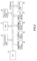
- FIG. 2 is a diagram of the system configuration of one embodiment of the paper-feed control apparatus in accordance with the present invention.
- FIG. 3 is a flow chart of the processing of paper-feed control in the embodiment shown in FIG. 2.
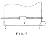
- FIG. 4 is a diagram illustrative of separator tabs in the paper tray of the paper-feed mechanism shown in FIG. 1.
- FIG. 5 illustrates the operation of the separator tabs of FIG. 4.
- FIG. 1 A cross-sectional view of one example of the paper-feed mechanism that is the main component of a printer to which the present invention is applied is shown in FIG. 1.
- a stack of a large number of sheets of paper is piled in a paper tray 1.
- a feed roller 3 that provides the paper feed is in contact with the top of this stack of paper.
- This feed roller 3 is designed to be driven by a paper-feed motor that is not shown in the figure. In this case, a stepping motor that goes through 360 steps in one rotation is used as the paper-feed motor.
- Separator tabs 5 are provided in the vicinity of a leading-edge portion of the paper tray 1, in the paper-feed direction.
- separator tabs 5 operate to separate the uppermost sheet of paper of the stack from the second and lower sheets in the stack, every time the paper feed is activated by the feed roller 3. In other words, the leading edge in the paper-feed direction of the uppermost sheet of paper is flexed thereby so that it is separated from the second and subsequent sheets of paper. This flexing of the uppermost sheet of paper is subsequently removed by the paper feed initiated by the feed roller 3, and the uppermost sheet alone is fed out over the separator tabs 5. This uppermost sheet of paper is then sent along a conveyor path by the feed roller 3. During this time, a paper-transfer guide 7 on the conveyor path ensures that the paper is sent correctly by a paper-transfer roller 9 while it is in contact with the paper-transfer guide 7.
- a paper-detection lever 11 is attached by a spring in the vicinity of the paper-transfer guide 7, in order to detect that the paper has been conveyed as far as the paper-transfer roller 9. If the paper has been transferred as far as the paper-detection lever 11, the paper-detection lever 11 is pushed upwards by the paper and an electrical switch that is not shown in the figure is turned on thereby. This turning on of the switch detects that the paper has been transferred correctly, or rather, that the paper feed has been successful. However, if the paper has not arrived at the paper-detection lever 11 even after a predetermined time has elapsed after the paper feed started, it is determined that a malfunction has occurred in the paper feed and a paper-feed halt signal is generated.
- the paper-feed can malfunction if the load applied to the paper in the opposite direction to the conveyor direction when the paper is conveyed is greater than the force with which the feed roller 3 conveys the paper, in other words, than the frictional force between the roller and the paper.
- the present invention is designed to operate the feed roller 3 intermittently once a paper-feed malfunction has been detected, in order to repeatedly generate a frictional force and thus ensure a high conveyor force. In this manner, the present invention is characterized in that it can overcome the load generated when the paper is conveyed, and thus ensure that the paper feed proceeds normally.
- FIG. 2 The system configuration of the controller that controls the paper feed is shown in FIG. 2.
- This system is provided with a CPU 13 for controlling the entire printer, including the control of the paper-feed operation.
- the CPU 13 is connected via a system bus to a programmable ROM 15 that contains programs for running the CPU 13, a RAM 17 used by the CPU 13 for various types of processing, and an operating panel 19 which has a buttons for operations such as starting and stopping the printer, or a display for showing various messages including error messages.
- the CPU 13 is also connected via the system bus to a drive circuit 25 of a paper-feed motor that drives the feed roller, and a paper detection switch 27 that is operated by the paper-detection lever 11.
- the CPU 13 In addition to paper-feed control, the CPU 13 also controls the processing of print data sent from a host computer, which is not shown in the figure, and the driving of the print head that prints the data and the carriage that moves the print head.
- this system bus is also connected to an interface unit 29 for communicating with the host computer, a drive circuit 23 for driving the carriage, and a drive circuit 21 for driving the print head.
- FIG. 3 A detailed flow of processing during the paper-feed performed by the controller shown in FIG. 2 is shown in FIG. 3.
- rotation of the paper-feed motor in the direction in which paper is conveyed is called the positive direction
- rotation in the direction opposite to that in which paper is conveyed is called the negative direction.
- this embodiment of the present invention uses a pulse motor as the paper-feed motor.
- step S1 when the paper feed starts, the value in a paper-feed counter that indicates the rotational distance of the paper-feed motor, or rather, the number of sheets of paper N that the motor has sent, is reset to zero (step S1).
- the paper-feed motor is rotated by one pulse in the positive direction (step S3).
- the value N in the paper-feed counter is then incremented by 1 (step S5).
- step S7 the system determines whether or not the paper has been detected by the paper sensor (step S7). If the paper has not yet been detected, the system determines whether or not the value N in the paper-feed counter has reached 1000 (step S9). In this case, a value of 1000 expresses a distance that is thought to be sufficient for the paper to reach the paper sensor after the start of the paper feed.
- the paper-feed motor is given 1000 pulses when paper feed is proceeding normally, the paper has plenty of time to reach the position of the paper sensor.
- the flow returns to the above described step S3 and once again the motor is operated in the positive direction by one pulse and the value N is incremented by one. This is repeated until the paper is detected by the paper sensor. In this manner, the paper-feed motor is rotated in the positive direction until the value N reaches its maximum value of 1000.
- step S11 If the paper is detected by the paper sensor before the value N reaches 1000, the paper-feed motor is rotated in the positive direction by 120 pulses (step S11) to convey the paper. This value of 120 pulses is equivalent to the distance necessary for the paper to be sent as far as printing portion that is not shown in the figures. Once the paper has been sent in this manner to the portion of the printer that performs the printing, paper-feed processing by a method that is known in the art starts for the printing (step S13).
- step S9 determines that the value N has reached 1000 before the paper is detected by the paper sensor
- the flow proceeds to a step S15.
- the paper-feed is halted for a predetermined short time, such as 0.5 seconds, and a value M that expresses the number of times the paper-feed is subjected to intermittent operation is reset to zero (step S15).
- This value of 0.5 seconds is the approximate time required for the position of the paper that has been flexed by the separator tabs to fall.
- the value N of the paper-feed counter is reset to zero and the number of intermittent operations M of the paper-feed motor is incremented by one (step S17).
- the paper-feed motor is rotated in the positive direction by one pulse (step S19) and the value N of the paper-feed counter is incremented by 1 (step S21).
- the system determines whether or not the paper has been detected (step S23). If the paper has been detected, the paper-feed motor is rotated in the positive direction by 200 pulses (step S25). This value of 200 pulses is equivalent to the distance necessary for the paper to be sent as far as the printing portion that is not shown in the figures.
- step S27 the system determines whether or not the value N has reached 60 (step S27).
- This value of 60 pulses is equivalent to the distance fed by one intermittent operation of the paper-feed motor.
- a 0.3-second wait time starts (step S29). This value of 0.3 seconds is the time required for the flexing in the angle of the paper away from the separator tabs to come off and return to its original orientation.
- the number of 60 pulses means that the number of paper-feed steps of the printer is 60.
- the intermittent operation consists of a feed of 60 pulses and a 0.3-second rest.
- step S31 the system checks whether the number of intermittent operations has reached a certain value, such as five (step S31). If the number has not yet reached five, the flow returns to step S17, the value in the paper-feed counter is reset to zero, and the number of intermittent operations M is incremented by one. This loop repeats until the number of intermittent operations M reaches the maximum value of five.
- step S23 If the paper is detected by the paper sensor in step S23 partway through this intermittent operation repetition loop, the paper-feed motor is rotated by 200 pulses (step S25) and paper-feed processing by a method that is known in the art then starts for the printing (step S13), in the same manner as described above.
- the value N in the paper-feed counter is reset to zero (step S33) and the paper-feed motor is rotated by one pulse in the positive direction (step S35).
- the value N is then incremented by one (step S37) and the system determines whether or not the paper has been detected (step S39). If the paper has been detected, the paper-feed motor is rotated in the positive direction by 200 pulses, in the same manner as in step S25. If the paper has not been detected, the system determines whether or not the value N has reached 400 (step S41) and repeats the processing until N reaches 400. However, if paper is detected by the paper sensor at step S39 partway through this loop, the flow branches to step S25 and the paper-feed processing for printing is performed, in the same manner as described above.
- the reliability of paper feed can be increased, without being affected by differences in paper quality, such as thickness.
- the system determines that a paper-feed failure has occurred, and displays an appropriate error message to prompt the user to perform recovery processing.
- the separator tabs 5 provided at the leading edge of the paper tray in this embodiment of the present invention are shown in FIG. 4. These separator tabs 5 are configured of a form that surrounds the corner portions of the paper and are provided at both sides of the leading edge in the conveyor direction of the paper tray 1, in such a manner as to guide the sides at the leading edge of the paper and also engage with the leading edge of the paper. As shown in the figure, the shape is such that the corner portions of the box are cut away into triangles, and the corners of the paper are enclosed therein.
- the length L of the separator tabs 5 in the direction along the sides of the paper is a length equivalent to approximately 60 steps of the stepping motor, which is the number of feed steps of the printer. Incidentally, one step is 1/360", which is approximately 0.07 mm.
- FIG. 5 The action of the paper with respect to the separator tabs 5 is illustrated in FIG. 5.
- the uppermost portion of FIG. 5 shows the paper engaged within the separator tabs 5 of the paper tray 1 and pushed up lightly by the elastic force of a spring.
- the paper With the paper in this state, if the paper is pushed forward enough from the trailing edge thereof that it flexes, as shown in the middle portion of FIG. 5, the paper flicks out from under the separator tabs 5 and lies on top of them, as shown in the lowermost portion of FIG. 5.
- This action of the paper from the flexing until it lies on top of the separator tabs 5 separates a single sheet of paper from the stack, without causing several sheets to be fed out. As a result, paper jamming is not likely to occur.
Landscapes
- Controlling Sheets Or Webs (AREA)
- Handling Of Cut Paper (AREA)
Applications Claiming Priority (2)
| Application Number | Priority Date | Filing Date | Title |
|---|---|---|---|
| JP14565/93 | 1993-02-01 | ||
| JP1456593 | 1993-02-01 |
Publications (3)
| Publication Number | Publication Date |
|---|---|
| EP0609747A2 true EP0609747A2 (de) | 1994-08-10 |
| EP0609747A3 EP0609747A3 (de) | 1995-02-22 |
| EP0609747B1 EP0609747B1 (de) | 1997-04-02 |
Family
ID=11864682
Family Applications (1)
| Application Number | Title | Priority Date | Filing Date |
|---|---|---|---|
| EP94100998A Expired - Lifetime EP0609747B1 (de) | 1993-02-01 | 1994-01-24 | Papiertransportsteuervorrichtung für einen Drucker |
Country Status (4)
| Country | Link |
|---|---|
| US (1) | US5531435A (de) |
| EP (1) | EP0609747B1 (de) |
| DE (1) | DE69402344T2 (de) |
| SG (1) | SG67892A1 (de) |
Cited By (1)
| Publication number | Priority date | Publication date | Assignee | Title |
|---|---|---|---|---|
| US11230124B2 (en) | 2018-04-11 | 2022-01-25 | Hewlett-Packard Development Company, L.P. | Reprints of delayed pages |
Families Citing this family (11)
| Publication number | Priority date | Publication date | Assignee | Title |
|---|---|---|---|---|
| US6227534B1 (en) | 1999-11-12 | 2001-05-08 | Lexmark International, Inc. | Method and apparatus for controlling an auto compensation pick mechanism to reduce the occurence of multi-feeds |
| US6485013B2 (en) * | 2000-12-04 | 2002-11-26 | Hewlett-Packard Company | Method and apparatus for detecting media level in a cassette |
| US7258335B2 (en) * | 2004-08-24 | 2007-08-21 | Lexmark International, Inc. | Eliminating drag of media sensor in printer media transport |
| JP4944445B2 (ja) * | 2006-01-05 | 2012-05-30 | 株式会社リコー | 画像形成装置、搬送方法、及びプログラム |
| US7484731B2 (en) * | 2006-08-28 | 2009-02-03 | Hewlett-Packard Development Company, L.P. | Printing device and method |
| JP5153253B2 (ja) * | 2007-08-10 | 2013-02-27 | キヤノン株式会社 | 給紙装置及び記録装置 |
| JP2010228841A (ja) * | 2009-03-26 | 2010-10-14 | Canon Inc | 給紙装置及び画像形成装置 |
| WO2013019186A1 (en) | 2011-07-29 | 2013-02-07 | Hewlett-Packard Development Company, L.P. | Printer |
| JP2013139336A (ja) * | 2011-12-05 | 2013-07-18 | Canon Inc | シート給送装置及び画像形成装置 |
| US8573585B1 (en) | 2012-05-30 | 2013-11-05 | Hewlett-Packard Development Company, L.P. | Media handling system |
| CN105172389A (zh) * | 2015-09-09 | 2015-12-23 | 宁波荣大昌办公设备有限公司 | 一种打印机送纸打印的控制系统及方法 |
Family Cites Families (8)
| Publication number | Priority date | Publication date | Assignee | Title |
|---|---|---|---|---|
| US4110032A (en) * | 1976-12-20 | 1978-08-29 | International Business Machines Corporation | Copy production machines having supply sheet pick retry |
| US4444385A (en) * | 1982-01-18 | 1984-04-24 | Qume Corporation | Sheet feeder |
| IT1152183B (it) * | 1982-05-17 | 1986-12-31 | Rockwell Rimoldi Spa | Dispositivo rilevatore di presa dei pezzi prelevati da una testina di prelievo |
| JPS59187880A (ja) * | 1983-04-08 | 1984-10-25 | Toshiba Corp | 搬送異常解除方法 |
| JPS63130440U (de) * | 1987-02-18 | 1988-08-25 | ||
| JP2696857B2 (ja) * | 1987-10-23 | 1998-01-14 | ソニー株式会社 | プリンタ |
| JPH01168468A (ja) * | 1987-12-25 | 1989-07-03 | Fujitsu Ltd | 用紙処理装置の制御方式 |
| US5056771A (en) * | 1989-08-25 | 1991-10-15 | Lexmark International, Inc. | Apparatus for controlling interpage gaps in printers and method of interpage gap control |
-
1994
- 1994-01-24 DE DE69402344T patent/DE69402344T2/de not_active Expired - Fee Related
- 1994-01-24 SG SG1996003526A patent/SG67892A1/en unknown
- 1994-01-24 EP EP94100998A patent/EP0609747B1/de not_active Expired - Lifetime
-
1995
- 1995-07-06 US US08/500,313 patent/US5531435A/en not_active Expired - Lifetime
Cited By (1)
| Publication number | Priority date | Publication date | Assignee | Title |
|---|---|---|---|---|
| US11230124B2 (en) | 2018-04-11 | 2022-01-25 | Hewlett-Packard Development Company, L.P. | Reprints of delayed pages |
Also Published As
| Publication number | Publication date |
|---|---|
| DE69402344T2 (de) | 1997-11-06 |
| EP0609747A3 (de) | 1995-02-22 |
| EP0609747B1 (de) | 1997-04-02 |
| DE69402344D1 (de) | 1997-05-07 |
| US5531435A (en) | 1996-07-02 |
| SG67892A1 (en) | 1999-10-19 |
Similar Documents
| Publication | Publication Date | Title |
|---|---|---|
| EP0609747B1 (de) | Papiertransportsteuervorrichtung für einen Drucker | |
| JP5795001B2 (ja) | プリンタ装置およびプリンタ装置の用紙送り方法 | |
| US6786481B2 (en) | Sheet feeding device | |
| US6007062A (en) | Method and apparatus for removing a jammed paper from an ink-jet printer | |
| US4300756A (en) | In-feed paper buckle control apparatus | |
| JP3218912B2 (ja) | プリント方法ならびにプリンタ装置 | |
| US4754961A (en) | Sheet feeding clutch mechanism for a sheet feeding unit | |
| EP0537775B1 (de) | Blattzuführvorrichtung für einen Drucker | |
| JPH0664255A (ja) | 印字装置 | |
| JPH0413152B2 (de) | ||
| JP3444055B2 (ja) | 用紙送出機構 | |
| US5557369A (en) | Recording apparatus with detection of manually inserted recording sheet | |
| JP3196913B2 (ja) | プリンタの給紙制御装置 | |
| US9409733B2 (en) | Conveying apparatus and printing apparatus | |
| JP4581303B2 (ja) | シート搬送装置 | |
| JP4755747B2 (ja) | 画像形成装置 | |
| JPH03227852A (ja) | 印字装置用自動給紙装置 | |
| KR100529340B1 (ko) | 프린터의 용지이송방법 | |
| GB2297315A (en) | Removing skew from paper fed to a printer | |
| JP2653736B2 (ja) | プリンタの用紙吸入制御方法 | |
| JPH0223147A (ja) | 用紙排出装置 | |
| JP2583675B2 (ja) | プリンタの給紙修正処理装置 | |
| JPS59222858A (ja) | 原稿自動給送装置における搬送制御方法 | |
| JPH03293174A (ja) | 印刷媒体の給紙方法 | |
| JPH02249840A (ja) | シート搬送装置 |
Legal Events
| Date | Code | Title | Description |
|---|---|---|---|
| PUAI | Public reference made under article 153(3) epc to a published international application that has entered the european phase |
Free format text: ORIGINAL CODE: 0009012 |
|
| AK | Designated contracting states |
Kind code of ref document: A2 Designated state(s): DE FR GB |
|
| PUAL | Search report despatched |
Free format text: ORIGINAL CODE: 0009013 |
|
| AK | Designated contracting states |
Kind code of ref document: A3 Designated state(s): DE FR GB |
|
| 17P | Request for examination filed |
Effective date: 19950328 |
|
| 17Q | First examination report despatched |
Effective date: 19950719 |
|
| GRAG | Despatch of communication of intention to grant |
Free format text: ORIGINAL CODE: EPIDOS AGRA |
|
| GRAH | Despatch of communication of intention to grant a patent |
Free format text: ORIGINAL CODE: EPIDOS IGRA |
|
| GRAH | Despatch of communication of intention to grant a patent |
Free format text: ORIGINAL CODE: EPIDOS IGRA |
|
| GRAA | (expected) grant |
Free format text: ORIGINAL CODE: 0009210 |
|
| AK | Designated contracting states |
Kind code of ref document: B1 Designated state(s): DE FR GB |
|
| REF | Corresponds to: |
Ref document number: 69402344 Country of ref document: DE Date of ref document: 19970507 |
|
| ET | Fr: translation filed | ||
| PLBE | No opposition filed within time limit |
Free format text: ORIGINAL CODE: 0009261 |
|
| STAA | Information on the status of an ep patent application or granted ep patent |
Free format text: STATUS: NO OPPOSITION FILED WITHIN TIME LIMIT |
|
| 26N | No opposition filed | ||
| REG | Reference to a national code |
Ref country code: GB Ref legal event code: IF02 |
|
| PGFP | Annual fee paid to national office [announced via postgrant information from national office to epo] |
Ref country code: DE Payment date: 20070118 Year of fee payment: 14 |
|
| PGFP | Annual fee paid to national office [announced via postgrant information from national office to epo] |
Ref country code: GB Payment date: 20070124 Year of fee payment: 14 |
|
| PGFP | Annual fee paid to national office [announced via postgrant information from national office to epo] |
Ref country code: FR Payment date: 20070109 Year of fee payment: 14 |
|
| GBPC | Gb: european patent ceased through non-payment of renewal fee |
Effective date: 20080124 |
|
| PG25 | Lapsed in a contracting state [announced via postgrant information from national office to epo] |
Ref country code: DE Free format text: LAPSE BECAUSE OF NON-PAYMENT OF DUE FEES Effective date: 20080801 |
|
| REG | Reference to a national code |
Ref country code: FR Ref legal event code: ST Effective date: 20081029 |
|
| PG25 | Lapsed in a contracting state [announced via postgrant information from national office to epo] |
Ref country code: GB Free format text: LAPSE BECAUSE OF NON-PAYMENT OF DUE FEES Effective date: 20080124 |
|
| PG25 | Lapsed in a contracting state [announced via postgrant information from national office to epo] |
Ref country code: FR Free format text: LAPSE BECAUSE OF NON-PAYMENT OF DUE FEES Effective date: 20080131 |