EP0610002B1 - Form zum Spritzgiessen von thermoplastischem Kunststoff - Google Patents
Form zum Spritzgiessen von thermoplastischem Kunststoff Download PDFInfo
- Publication number
- EP0610002B1 EP0610002B1 EP94300434A EP94300434A EP0610002B1 EP 0610002 B1 EP0610002 B1 EP 0610002B1 EP 94300434 A EP94300434 A EP 94300434A EP 94300434 A EP94300434 A EP 94300434A EP 0610002 B1 EP0610002 B1 EP 0610002B1
- Authority
- EP
- European Patent Office
- Prior art keywords
- mold
- cavity
- insulating layer
- injection molding
- block
- Prior art date
- Legal status (The legal status is an assumption and is not a legal conclusion. Google has not performed a legal analysis and makes no representation as to the accuracy of the status listed.)
- Expired - Lifetime
Links
- 238000001746 injection moulding Methods 0.000 title claims abstract description 41
- 229920005992 thermoplastic resin Polymers 0.000 title claims abstract description 22
- 229920005989 resin Polymers 0.000 claims abstract description 98
- 239000011347 resin Substances 0.000 claims abstract description 98
- 238000009413 insulation Methods 0.000 claims abstract description 9
- 239000000463 material Substances 0.000 claims description 50
- 229910052751 metal Inorganic materials 0.000 claims description 30
- 239000002184 metal Substances 0.000 claims description 30
- 238000000576 coating method Methods 0.000 claims description 28
- 239000011248 coating agent Substances 0.000 claims description 24
- NBVXSUQYWXRMNV-UHFFFAOYSA-N fluoromethane Chemical compound FC NBVXSUQYWXRMNV-UHFFFAOYSA-N 0.000 claims description 23
- VYPSYNLAJGMNEJ-UHFFFAOYSA-N Silicium dioxide Chemical compound O=[Si]=O VYPSYNLAJGMNEJ-UHFFFAOYSA-N 0.000 claims description 21
- 229920003023 plastic Polymers 0.000 claims description 19
- 239000004033 plastic Substances 0.000 claims description 19
- 239000011521 glass Substances 0.000 claims description 16
- 238000000034 method Methods 0.000 claims description 16
- 230000008569 process Effects 0.000 claims description 11
- 229910010293 ceramic material Inorganic materials 0.000 claims description 10
- 239000000805 composite resin Substances 0.000 claims description 10
- 239000000037 vitreous enamel Substances 0.000 claims description 8
- XUIMIQQOPSSXEZ-UHFFFAOYSA-N Silicon Chemical compound [Si] XUIMIQQOPSSXEZ-UHFFFAOYSA-N 0.000 claims description 6
- 239000002131 composite material Substances 0.000 claims description 6
- 229910052710 silicon Inorganic materials 0.000 claims description 6
- 239000010703 silicon Substances 0.000 claims description 6
- 229920002050 silicone resin Polymers 0.000 claims description 6
- 238000007747 plating Methods 0.000 claims description 5
- 229910044991 metal oxide Inorganic materials 0.000 claims description 4
- 150000004706 metal oxides Chemical class 0.000 claims description 4
- 229910052814 silicon oxide Inorganic materials 0.000 claims description 4
- XLYOFNOQVPJJNP-UHFFFAOYSA-N water Substances O XLYOFNOQVPJJNP-UHFFFAOYSA-N 0.000 claims description 3
- 239000006185 dispersion Substances 0.000 claims description 2
- 239000010410 layer Substances 0.000 description 129
- PXHVJJICTQNCMI-UHFFFAOYSA-N Nickel Chemical compound [Ni] PXHVJJICTQNCMI-UHFFFAOYSA-N 0.000 description 48
- 229910000831 Steel Inorganic materials 0.000 description 38
- 239000010959 steel Substances 0.000 description 38
- 238000000465 moulding Methods 0.000 description 33
- 238000002347 injection Methods 0.000 description 26
- 239000007924 injection Substances 0.000 description 26
- 229910052759 nickel Inorganic materials 0.000 description 24
- 239000003822 epoxy resin Substances 0.000 description 16
- 229920000647 polyepoxide Polymers 0.000 description 16
- 230000000052 comparative effect Effects 0.000 description 10
- 239000003365 glass fiber Substances 0.000 description 10
- 238000012546 transfer Methods 0.000 description 10
- 238000001816 cooling Methods 0.000 description 9
- 239000000377 silicon dioxide Substances 0.000 description 9
- MCMNRKCIXSYSNV-UHFFFAOYSA-N Zirconium dioxide Chemical compound O=[Zr]=O MCMNRKCIXSYSNV-UHFFFAOYSA-N 0.000 description 8
- 229920000122 acrylonitrile butadiene styrene Polymers 0.000 description 7
- 230000007547 defect Effects 0.000 description 7
- 239000010409 thin film Substances 0.000 description 7
- 239000000203 mixture Substances 0.000 description 6
- 239000004417 polycarbonate Substances 0.000 description 6
- 150000002739 metals Chemical class 0.000 description 5
- -1 polytetrafluoroethylene, tetrafluoroethylene-hexafluoropropylene copolymer Polymers 0.000 description 5
- 239000002344 surface layer Substances 0.000 description 5
- 239000004642 Polyimide Substances 0.000 description 4
- 239000010408 film Substances 0.000 description 4
- 230000006872 improvement Effects 0.000 description 4
- 230000003287 optical effect Effects 0.000 description 4
- 229920001721 polyimide Polymers 0.000 description 4
- 238000007711 solidification Methods 0.000 description 4
- 230000008023 solidification Effects 0.000 description 4
- 239000000919 ceramic Substances 0.000 description 3
- RVTZCBVAJQQJTK-UHFFFAOYSA-N oxygen(2-);zirconium(4+) Chemical compound [O-2].[O-2].[Zr+4] RVTZCBVAJQQJTK-UHFFFAOYSA-N 0.000 description 3
- 229920005668 polycarbonate resin Polymers 0.000 description 3
- 239000004431 polycarbonate resin Substances 0.000 description 3
- 235000012239 silicon dioxide Nutrition 0.000 description 3
- 229910001928 zirconium oxide Inorganic materials 0.000 description 3
- 239000004734 Polyphenylene sulfide Substances 0.000 description 2
- GWEVSGVZZGPLCZ-UHFFFAOYSA-N Titan oxide Chemical compound O=[Ti]=O GWEVSGVZZGPLCZ-UHFFFAOYSA-N 0.000 description 2
- 230000008901 benefit Effects 0.000 description 2
- 230000003111 delayed effect Effects 0.000 description 2
- 230000000694 effects Effects 0.000 description 2
- 238000004070 electrodeposition Methods 0.000 description 2
- 238000005516 engineering process Methods 0.000 description 2
- 238000002474 experimental method Methods 0.000 description 2
- 238000004519 manufacturing process Methods 0.000 description 2
- 229920000069 polyphenylene sulfide Polymers 0.000 description 2
- 239000000843 powder Substances 0.000 description 2
- 230000002035 prolonged effect Effects 0.000 description 2
- 238000007712 rapid solidification Methods 0.000 description 2
- 239000000243 solution Substances 0.000 description 2
- 239000000126 substance Substances 0.000 description 2
- 238000012360 testing method Methods 0.000 description 2
- 229910000838 Al alloy Inorganic materials 0.000 description 1
- 229910001369 Brass Inorganic materials 0.000 description 1
- OKTJSMMVPCPJKN-UHFFFAOYSA-N Carbon Chemical compound [C] OKTJSMMVPCPJKN-UHFFFAOYSA-N 0.000 description 1
- RYGMFSIKBFXOCR-UHFFFAOYSA-N Copper Chemical compound [Cu] RYGMFSIKBFXOCR-UHFFFAOYSA-N 0.000 description 1
- 229910000881 Cu alloy Inorganic materials 0.000 description 1
- 229910000990 Ni alloy Inorganic materials 0.000 description 1
- 239000002033 PVDF binder Substances 0.000 description 1
- 239000004696 Poly ether ether ketone Substances 0.000 description 1
- 239000004693 Polybenzimidazole Substances 0.000 description 1
- 239000004695 Polyether sulfone Substances 0.000 description 1
- 239000004721 Polyphenylene oxide Substances 0.000 description 1
- 229910001069 Ti alloy Inorganic materials 0.000 description 1
- RTAQQCXQSZGOHL-UHFFFAOYSA-N Titanium Chemical compound [Ti] RTAQQCXQSZGOHL-UHFFFAOYSA-N 0.000 description 1
- WGLPBDUCMAPZCE-UHFFFAOYSA-N Trioxochromium Chemical compound O=[Cr](=O)=O WGLPBDUCMAPZCE-UHFFFAOYSA-N 0.000 description 1
- QCWXUUIWCKQGHC-UHFFFAOYSA-N Zirconium Chemical compound [Zr] QCWXUUIWCKQGHC-UHFFFAOYSA-N 0.000 description 1
- 229910045601 alloy Inorganic materials 0.000 description 1
- 239000000956 alloy Substances 0.000 description 1
- 229910052782 aluminium Inorganic materials 0.000 description 1
- XAGFODPZIPBFFR-UHFFFAOYSA-N aluminium Chemical compound [Al] XAGFODPZIPBFFR-UHFFFAOYSA-N 0.000 description 1
- 230000015572 biosynthetic process Effects 0.000 description 1
- 238000000071 blow moulding Methods 0.000 description 1
- 239000010951 brass Substances 0.000 description 1
- 229910052799 carbon Inorganic materials 0.000 description 1
- 229910000423 chromium oxide Inorganic materials 0.000 description 1
- 238000000748 compression moulding Methods 0.000 description 1
- 229920001577 copolymer Polymers 0.000 description 1
- 239000010949 copper Substances 0.000 description 1
- 229910052802 copper Inorganic materials 0.000 description 1
- 230000003247 decreasing effect Effects 0.000 description 1
- 230000001419 dependent effect Effects 0.000 description 1
- 238000011161 development Methods 0.000 description 1
- SOCTUWSJJQCPFX-UHFFFAOYSA-N dichromate(2-) Chemical compound [O-][Cr](=O)(=O)O[Cr]([O-])(=O)=O SOCTUWSJJQCPFX-UHFFFAOYSA-N 0.000 description 1
- QDOXWKRWXJOMAK-UHFFFAOYSA-N dichromium trioxide Chemical compound O=[Cr]O[Cr]=O QDOXWKRWXJOMAK-UHFFFAOYSA-N 0.000 description 1
- 238000007598 dipping method Methods 0.000 description 1
- 238000009503 electrostatic coating Methods 0.000 description 1
- 230000008030 elimination Effects 0.000 description 1
- 238000003379 elimination reaction Methods 0.000 description 1
- 229920006351 engineering plastic Polymers 0.000 description 1
- 239000012765 fibrous filler Substances 0.000 description 1
- 238000010285 flame spraying Methods 0.000 description 1
- 238000005187 foaming Methods 0.000 description 1
- 238000010438 heat treatment Methods 0.000 description 1
- 239000011256 inorganic filler Substances 0.000 description 1
- 229910003475 inorganic filler Inorganic materials 0.000 description 1
- 238000003780 insertion Methods 0.000 description 1
- 230000037431 insertion Effects 0.000 description 1
- 239000004973 liquid crystal related substance Substances 0.000 description 1
- 239000007769 metal material Substances 0.000 description 1
- 238000012986 modification Methods 0.000 description 1
- 230000004048 modification Effects 0.000 description 1
- 239000012778 molding material Substances 0.000 description 1
- 238000010137 moulding (plastic) Methods 0.000 description 1
- 229920002480 polybenzimidazole Polymers 0.000 description 1
- 229920002530 polyetherether ketone Polymers 0.000 description 1
- 238000006116 polymerization reaction Methods 0.000 description 1
- 229920001296 polysiloxane Polymers 0.000 description 1
- 229920001343 polytetrafluoroethylene Polymers 0.000 description 1
- 239000004810 polytetrafluoroethylene Substances 0.000 description 1
- 229920002981 polyvinylidene fluoride Polymers 0.000 description 1
- 238000002360 preparation method Methods 0.000 description 1
- LIVNPJMFVYWSIS-UHFFFAOYSA-N silicon monoxide Chemical class [Si-]#[O+] LIVNPJMFVYWSIS-UHFFFAOYSA-N 0.000 description 1
- 239000005361 soda-lime glass Substances 0.000 description 1
- 239000007787 solid Substances 0.000 description 1
- 238000005507 spraying Methods 0.000 description 1
- 238000004544 sputter deposition Methods 0.000 description 1
- 239000010935 stainless steel Substances 0.000 description 1
- 229910001220 stainless steel Inorganic materials 0.000 description 1
- 238000005728 strengthening Methods 0.000 description 1
- IIACRCGMVDHOTQ-UHFFFAOYSA-M sulfamate Chemical compound NS([O-])(=O)=O IIACRCGMVDHOTQ-UHFFFAOYSA-M 0.000 description 1
- 229920001187 thermosetting polymer Polymers 0.000 description 1
- 239000010936 titanium Substances 0.000 description 1
- 229910052719 titanium Inorganic materials 0.000 description 1
- OGIDPMRJRNCKJF-UHFFFAOYSA-N titanium oxide Inorganic materials [Ti]=O OGIDPMRJRNCKJF-UHFFFAOYSA-N 0.000 description 1
- 229910052726 zirconium Inorganic materials 0.000 description 1
Images
Classifications
-
- B—PERFORMING OPERATIONS; TRANSPORTING
- B29—WORKING OF PLASTICS; WORKING OF SUBSTANCES IN A PLASTIC STATE IN GENERAL
- B29C—SHAPING OR JOINING OF PLASTICS; SHAPING OF MATERIAL IN A PLASTIC STATE, NOT OTHERWISE PROVIDED FOR; AFTER-TREATMENT OF THE SHAPED PRODUCTS, e.g. REPAIRING
- B29C33/00—Moulds or cores; Details thereof or accessories therefor
- B29C33/38—Moulds or cores; Details thereof or accessories therefor characterised by the material or the manufacturing process
- B29C33/3828—Moulds made of at least two different materials having different thermal conductivities
-
- B—PERFORMING OPERATIONS; TRANSPORTING
- B29—WORKING OF PLASTICS; WORKING OF SUBSTANCES IN A PLASTIC STATE IN GENERAL
- B29C—SHAPING OR JOINING OF PLASTICS; SHAPING OF MATERIAL IN A PLASTIC STATE, NOT OTHERWISE PROVIDED FOR; AFTER-TREATMENT OF THE SHAPED PRODUCTS, e.g. REPAIRING
- B29C33/00—Moulds or cores; Details thereof or accessories therefor
- B29C33/56—Coatings, e.g. enameled or galvanised; Releasing, lubricating or separating agents
-
- B—PERFORMING OPERATIONS; TRANSPORTING
- B29—WORKING OF PLASTICS; WORKING OF SUBSTANCES IN A PLASTIC STATE IN GENERAL
- B29C—SHAPING OR JOINING OF PLASTICS; SHAPING OF MATERIAL IN A PLASTIC STATE, NOT OTHERWISE PROVIDED FOR; AFTER-TREATMENT OF THE SHAPED PRODUCTS, e.g. REPAIRING
- B29C45/00—Injection moulding, i.e. forcing the required volume of moulding material through a nozzle into a closed mould; Apparatus therefor
- B29C45/17—Component parts, details or accessories; Auxiliary operations
- B29C45/26—Moulds
- B29C45/37—Mould cavity walls, i.e. the inner surface forming the mould cavity, e.g. linings
-
- B—PERFORMING OPERATIONS; TRANSPORTING
- B29—WORKING OF PLASTICS; WORKING OF SUBSTANCES IN A PLASTIC STATE IN GENERAL
- B29K—INDEXING SCHEME ASSOCIATED WITH SUBCLASSES B29B, B29C OR B29D, RELATING TO MOULDING MATERIALS OR TO MATERIALS FOR MOULDS, REINFORCEMENTS, FILLERS OR PREFORMED PARTS, e.g. INSERTS
- B29K2883/00—Use of polymers having silicon, with or without sulfur, nitrogen, oxygen, or carbon only, in the main chain, as mould material
Definitions
- the present invention relates to a mold for injection molding of a thermoplastic resin according to the precharacterising part of claim 1.
- a mold of this type is known from e.g. JP-A-55-55 839.
- the present invention further relates to a process for fabricating thermoplastic resin articles.
- thermoplastic resin articles are made of metals such as conventional steel, nickel, nickel alloys, aluminum, aluminum alloys, copper, copper alloys, etc.
- a molten resin is introduced into a cavity under pressure to be molded to a predetermined shape and size.
- this molding technique generally a more precise article with good appearance can be obtained compared with other molding techniques such as blow molding, etc.
- the pattern on the cavity surface is difficult to be transferred to the article without blurring or losing its original fineness and gloss. If such blurring occurs in the pattern transferred to the article, the appearance of the article is spoiled, and its commercial value is lost.
- weld lines and flow marks are likely to remain on the surface of the article, as well as sink marks are likely to remain near an end part or on thick wall portions of the article.
- the temperature of the mold or the injection pressure is increased.
- the increase in temperature of the mold leads to a prolonged cycle time of molding.
- satisfactory results cannot be obtained.
- the increase in injection pressure there is also a limit to the improvement of the transfer accuracy.
- the increase in injection pressure causes warpage due to residual strain, and causes much flashing, etc., resulting in degraded quality of articles.
- the increase in injection pressure needs the enlargement of a molding machine, and the strengthening of the mold. Accordingly, this makes it difficult to economically fabricate satisfactory articles.
- the mold for injection molding is made of metals which generally have good thermal conductivity.
- the molten resin gives off heat to the cavity surface with rapid cooling; consequently a solid layer is immediately formed on the surface of the molten resin.
- the internal pressure of the molten resin is relatively low, and the rapid solidification takes place on the very surface of molten resin prior to the completion of filling.
- sink marks are substantially prevented from being formed.
- the unsatisfactory transfer of the pattern from the cavity surface to the article cannot be improved due to the fast solidification of the surface layer of the molten resin during filling, and phenomena of flow marks and weld lines also remain to be unimproved.
- articles with good surface quality cannot be obtained at a low molding pressure by these processes.
- the solidification of the surface layer of the molten resin is delayed, and in the process 6), the adhesion between the injected molten resin and the cavity surface is improved due to the coating film therebetween.
- the transfer of the pattern from the cavity surface to articles is improved.
- sink marks cannot be prevented from being formed near the end portions of the article against gate and/or on the thick wall portions of the articles, requiring high pressure molding for eliminating them.
- EP-A-0 437 345 It is known from EP-A-0 437 345 to provide a mold used for fabricating a thermoplastic resin, in which an insulating film is formed on both sides of the cavity block and the core block. The same material is used throughout the cavity.
- US-A-4,225,109 discloses an insulated metal mold having a molding surface defining the cavity of a mold for molding a thermoplastic resin.
- the molding surface is provided by a thin metal layer and a heat insulating layer.
- the thin metal layer and the heat insulating layer on the core block side are made from the same materials as those of the cavity block side.
- W089/10829 also discloses a mold having an insulating layer and a metal surface layer on both of the cavity surfaces of the mold.
- the thin metal layer and the heat insulating layer on the core block side are made from the same materials as those of the cavity block side.
- CH-A-533003 discloses a method of manufacturing smooth plastic molding, in which the inner walls of the mold and supply pipes are coated with carbon tetraflouride as an insulating layer.
- JP-A-55-55839 discloses a film of ceramic, fluororesin or thermosetting resin provided on the surface of a mold cavity.
- JP-A-61-79611 discloses the use of a film consisting of fluoropolymeric material on the surface of a mold cavity.
- a mold for injection molding of a thermoplastic resin comprising: a cavity block, a core block, and a cavity which is formed between the cavity block and the core block and which is adapted, in use, to be filled with a molten resin, the cavity block having an insulating layer on the cavity side, the insulating layer being made of a material selected from the group consisting of ceramic materials, porcelain enamel, glass materials and heat-resistant plastic materials, characterised in that the insulating layer optionally being made of a material selected from composites of ceramic materials, porcelain enamel, glass materials and heat-resistant plastic materials and in that the core block has a release-functioned insulating layer on the cavity side, the release-functioned insulating layer having both functions of mold releasing and heat insulation and being made of a material selected from the group consisting of fluorocarbon resins, fluorocarbon resin composite materials, silicone resin composite materials, and metal platings with fluorocarbon resin dispersion; such that, when the cavity has
- the insulating layer preferably has a thermal conductivity preferably less than 8 x 10 -3 cal/cm ⁇ sec ⁇ °C and a thickness of 0.02 to 1 mm. Only for the mold for an optical article, as an exception, the thickness of the insulating layer preferably made of a ceramic material or a glass material is desirable in a range from 1 to 20 mm.
- a thin metal layer is further formed on the surface of the insulating layer.
- the insulating layer is made of a heat-resistant plastic material or a plastic composite material with a thickness of 0.3 to 3 mm and has a metal layer with a thickness of 0.001 to 0.5 mm on its surface.
- a thin surface coating with good wettability to the molten resin is further formed on the metal layer.
- the thin surface coating is made of one selected from the group consisting of a metal oxide, a silicon oxide, a silicon complex oxide, and a plastic material.
- the silicon complex oxide is one selected from the group consisting of glass materials and porcelain enamel.
- the thin surface coating has wettability with a contact angle of not more than 30° against water.
- the release-functioned insulating layer has a thermal conductivity of not more than 8 x 10 -3 cal/cm ⁇ sec ⁇ °C.
- the invention described herein gives a mold the advantage, which makes possible the accurate transfer of the gloss or fineness of the cavity surface to articles without any sink marks thereon at a low pressure such as two-third or less, in some cases, about one-fifth of that in using the conventional mold.
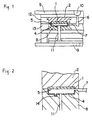
- Figure 1 is a cross-sectional view schematically showing an example of a mold for injection molding according to the present invention.
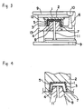
- Figure 2 is an enlarged view of a main portion of the mold shown in Figure 1.
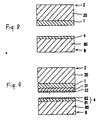
- Figure 3 is a cross-sectional view schematically showing another example of a mold for injection molding according to the present invention.
- Figure 4 is an enlarged view of a main portion of the mold shown in Figure 3.
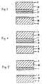
- Figure 5 is a cross-sectional view of a main portion of a mold for injection molding of one example according to the present invention.
- Figure 6 is a cross-sectional view of a main portion of a mold for injection molding of another example according to the present invention.
- Figure 7 is a cross-sectional view of a main portion of a mold for injection molding of another example according to the present invention.
- Figure 8 is a cross-sectional view of a main portion of a mold for injection molding of another example according to the present invention.
- Figure 9 is a cross-sectional view of a main portion of a mold for injection molding of another example according to the present invention.
- the inventors of the present invention studied the wettability between the cavity surface and the molten resin, for resolving the above-mentioned problems. The result of the study will be outlined below.
- Each block (4 cm x 4 cm x 1 cm) used for a cavity which was composed of the various materials listed in Table 1 was placed on a temperature-controlled heating platen. Then, a molten resin (ABS resin, 230°C, 8 g) was pressed against the surface of the block. By repeating this operation with varying the controlled temperature, the temperature of the block surface was measured, at which the molten resin began to adhere to the block due to the wettability developed therebetween (hereinafter, referred to as wettability-developing temperature). In addition, the time required for releasing the molten resin from the block surface (contact time) was measured, in which the temperature of the block surface was set to be 2°C higher than the wettability-developing temperature.
- composition of a block used for a wettability test is shown in Table 1, together with part of data obtained.
- the composition of a block used for a wettability test and representative data No. Materials for mold and their composition Wettability-developing temperature (°C) Contact time (sec.) at wettability-developing temperature plus 2°C 1.
- Epoxy resin 21 120 Steel coated with a 0.5 mm epoxy resin layer 51 3 6.
- Steel coated with a 1.0 mm epoxy resin layer 27 5 7.
- Metal materials have satisfactory thermal conductivity, such as 1.99 x 10 -1 cal/cm ⁇ sec ⁇ °C for steel.
- the molten resin When a molten resin at a high temperature comes into contact with steel, the molten resin is immediately cooled and forms a solidified layer on the surface. Therefore, the wettability dose not develop between the steel and the molten resin.
- the temperature of the steel surface For the wettability development, the temperature of the steel surface needs to be raised to 112°C or more.
- Ceramic materials such as zirconia, resin materials such as an epoxy resin, glass, and the like, have much lower thermal conductivity, compared with the metals (i.e., thermal conductivity of zirconia: 4 x 10 -3 to 7 x 10 -3 cal/cm ⁇ sec ⁇ °C, and that of an epoxy resin: 5 x 10 -4 cal/cm ⁇ sec ⁇ °C).
- thermal conductivity of zirconia 4 x 10 -3 to 7 x 10 -3 cal/cm ⁇ sec ⁇ °C
- an epoxy resin 5 x 10 -4 cal/cm ⁇ sec ⁇ °C
- the molten resin is not satisfactorily released from the surface of these blocks due to having low thermal conductivity. More specifically, although the wettability can develop on the surface of these blocks at a low temperature, it takes a long time for these blocks to give off heat and for the molded resin to be released from these blocks.
- the insulation coating of a resin, a ceramic material or a glass material on a metal may be considered to regulate the surface properties such as wettability and a heat discharge rate.
- the contact time can be controlled by varying the thickness of the insulation coating.
- the wettability will develop at a lower surface temperature. More specifically, in the case where the surface portion was composed of the above-mentioned thin film coated metal layer having a thickness of 0.1 mm, and the insulating layer having a thickness of 0.5 mm, the wettability could develop on the surface coating at a temperature of 59°C (i.e., 6°C lower than the case where such a thin surface coating was not provided). This is understandable from the comparison between No. 7 and No. 11 in Table 1.
- the improvement of wettability is effective to up-grading the product quality and/or to widening the ranges of optimum conditions, in molding not only conventional resins such as ABS, PE, PP, PS, PC, etc.; but also engineering plastics such as PC, PA, PBT, modified PPE, PPS, PES, liquid crystal resins, etc. as well as reinforced resins filled with fibrous or inorganic fillers, etc.
- the surface of a mother mold made of brass (5 cm x 5 cm x 3 cm) was mirror-polished, and the surface of the mother mold was release-treated with a bichromate solution. Then, nickel was plated with a sulfamate solution to a thickness of 0.1 mm onto the surface of the mother mold. Further, a heat-resistant insulating layer (1 mm) with high stiffness made of an epoxy resin composite material and backing steel (5 cm x 5 cm x 1 cm) was applied to the rear surface of the plated nickel in this order. Thereafter, the mother mold was removed from the laminated block mentioned above to obtain a cavity block.
- a core block was made of conventional steel. The cavity block and the core block were combined to construct a mold for injection molding.
- An ABS resin was injection molded using the mold thus obtained. Under the limited conditions of a mold temperature of 80°C to 85°C, a very low intracavity pressure of 100 kg/cm 2 , and the highest injection speed, a glossy article without any sink marks on its front surface which faced the cavity block during molding and with plenty of sink marks only on the rear surface which faced the core block was obtained. On the other hand, under the conditions other than these limited ones, sink marks were formed even on a part of or throughout the front surface.
- the inventors further studied a more suitable core block in detail.
- a layer having both insulation and satisfactory release property for example 0.05 mm of a fluorocarbon resin coating on the surface of the core block
- the pattern on the cavity surface is accurately transferred to the articles, under the broader conditions of a mold temperature of 62°C or more, an intra-cavity pressure of 100 kg/cm 2 or more, and from low to high injection speed.
- the article thus obtained had more sink marks on the rear surface, which led to no warpage due to the elimination of internal stresses in a low range of injection pressure.
- the purpose of providing the release-functioned insulating layer on the surface of the core block is as follows:
- the molten rein injected into the cavity is immediately cooled to shrink, and can be quickly released from the core surface under the condition that a portion of the molten resin facing the core surface keeps a high temperature.
- the air layer develops between the molten resin and the core surface, and then the air layer provides the remarkable insulating effect, delaying the cooling and helping the free shrinkage by molecular relaxation of the molten resin facing the core surface.
- the faster cooling without any shrinkage of the portion facing the cavity surface can be easily attained. Accordingly, the articles without any sink marks, on which the pattern of the cavity surface is accurately transferred, are obtained.
- Examples of a method for forming a release-functioned insulating layer on the core surface include a fluorocarbon resin coating method, a fluorocarbon resin composite coating method, a silicone resin composite coating method, a fluorocarbon resin-dispersed nickel plating, or the like.
- the fluorocarbon resin include polytetrafluoroethylene, tetrafluoroethylene-hexafluoropropylene copolymer, polyvinylidenefluoride, polychlorotrifluoroethylene, tetrafluoroethylene-ethylene copolymer, perfluoroalkylvinylether copolymer, etc.
- Examples of the fluorocarbon composite resin include mixtures of the fluorocarbon resin and other resins.
- the silicone type composite resins include silicone resin, mixtures of silicone resin and other resins.
- Stainless steel, a titanium-based alloy, and the like, having insulation much better than that of conventional steel, are desirable as a backing material for the core block of a mold.
- HDT heat distortion temperature
- PC reinforced with 30% glass fiber HDT 148°C at 18.5 kgf/cm 2 load
- PBT with 30% glass fiber HDT 210°C at 18.5 kgf/cm 2 load
- the resins with a glass fiber, having a high HDT begin to solidify at much higher temperature, and their shrinkage during solidification is much smaller, compared with that of unfilled resins.
- the mold shrinkage of unfilled PC is 0.5 to 0.7%, and that of PC with 30% glass fiber is 0.1 to 0.2% (from Modern Plastics Encyclopedia '91 Characteristic Table).
- the release-functioned insulating layer of the core block should be made sufficiently thick, compared with the insulating layer on the cavity block; for example, the thickness of the insulating layer on the cavity block is set at 0.5 mm and that of the release-functioned insulating layer on the core block is set at 5 mm.
- the pattern on the cavity surface is desirably transferred to the articles with sink marks only on the rear surface facing the core block.
- the wettability between the molten resin and the cavity surface is improved and its developing temperature is decreased by 5 to 10°C, by applying a thin surface coating with satisfactory wettability (e.g., SiO 2 coating) on the metal layer of the cavity block.
- a thin surface coating with satisfactory wettability e.g., SiO 2 coating
- the thin surface coating include metal oxides such as titanium oxide (TiO 2 ), chromium oxide (Cr 2 O 3 ), and zirconium oxide (ZrO 2 ); silicon oxides such as silicon dioxide (SiO 2 ); and silicon complex oxides such as glass, porcelain enamel, etc.
- the contact angles of the respective cavity block with such thin surface coatings against water is measured to be 30° (TiO 2 ), 13° (Cr 2 O 3 ), 27° (ZrO 2 ), 10° (SiO 2 ), 12° (glass), and so on.
- Plastics, excellent in affinity with a molten resin may also be used as the thin surface coating. In particular, a plastic thin film formed by plasma polymerization, electro-deposition, a dipping process, spray coating, electrostatic coating, etc. is preferred.
- the above-mentioned cavity block and core block are combined to make a mold.
- the pattern on the cavity surface is accurately transferred to the articles at a lower pressure (i.e., two-third or less of) than that in using a conventional mold.
- the articles have excellent appearance without any sink marks, flow marks, jetting, etc.
- the present invention makes it possible to fabricate such articles under the usual scope of molding conditions with a standard machine.
- the mold for injection molding according to the present invention includes a cavity block and a core block.
- a molten resin is filled into a cavity surrounded by the surface of the cavity and core blocks.
- On the cavity surface an insulating layer is applied for developing "wettability" against the injected resin and for controlling the heat discharge rate of it.
- the core surface has a release-functioned insulating layer thereon.
- the thermal conductivity of the insulating layer provided on the cavity surface is as low as possible.
- the thermal conductivity is preferably 8 x 10 -3 cal/cm ⁇ sec ⁇ °C or less, more preferably 5 x 10 -3 cal/cm ⁇ sec ⁇ °C or less.
- the thickness thereof is preferably 0.02 to 1 mm.
- the preferable thickness of which is 0.3 to 3 mm, more preferably 0.5 to 1.5 mm. If the thickness is less than 0.3 mm, weld lines, flow marks, etc. are still likely to be formed. If the thickness is more than 3 mm, a molding cycle is largely prolonged, resulting in unsatisfactory productivity.
- the thickness of the metal layer mentioned above is in the range of 0.001 to 0.5 mm, more preferably 0.01 to 0.2 mm.
- heat-resistant plastic materials examples include an epoxy resin, polyimide, polybenzimidazole, polyimidazopyrrolone, polyetheretherketone, polyphenylenesulfide, etc.
- a thin surface coating having satisfactory wettability to the molten resin is preferably formed on the surface of the metal layer.
- a thin surface coating is preferably made of a metal oxide, a silicon oxide, a silicon complex oxide (e.g., glass, porcelain enamel, etc.), or a plastic material.
- the thickness of the thin surface coating varies depending upon a material thereof or a preparation method thereof, it may be 5 ⁇ m or less.
- the release-functioned insulating layer on the core surface is preferably made of one selected from the group consisting of fluorocarbon resin (e.g., polytetrafluoroethylene), a fluorocarbon resin composite material, a silicone resin composite material, and a fluorocarbon resin-dispersed nickel, etc.
- fluorocarbon resin e.g., polytetrafluoroethylene
- a fluorocarbon resin composite material e.g., polytetrafluoroethylene
- a silicone resin composite material e.g., polymethyl methacrylate
- fluorocarbon resin-dispersed nickel e.g., nickel-dispersed nickel, etc.
- a thin and only release-functioned surface coating may be applied on a thick insulating layer.
- a thin metal layer on the thick insulating layer for the core block it is also possible to give the core surface an effective release function due to raising a release temperature, i.e., a wettability temperature, shown in Table
- the thickness of the release-functioned insulating layer is preferably 0.01 to 7 mm.
- the thickness of the release-functioned insulating layer may be 0.01 to 0.3 mm; while for an engineering resin the thickness of that layer should be increased up to 7 mm, depending on HDT of the resin used.
- the thickness of the release-functioned insulating layer is less than 0.01 mm, satisfactory insulation is not attained.
- the thickness of the insulating layer is more than 7 mm, the difference in cooling rate between the cavity and core surfaces becomes larger, which generates warpage in obtained articles, in some cases.
- the insulating layer zirconia as a representative of the former has a linear expansion coefficient of 8 x 10 -6 /°C to 11 x 10 -6 /°C and a thermal conductivity of 4 x 10 -3 cal/cm ⁇ sec ⁇ °C to 7 x 10 -3 cal/cm ⁇ sec ⁇ °C; the latter such as a soda-lime glass sheet has a linear expansion of 8 x 10 -6 /°C to 9 x 10 -6 /°C and a thermal conductivity of 1.8 x 10 -3 cal/cm ⁇ sec ⁇ °C. It is preferred that the thickness of the insulating layer is set to be larger (i.e., 1 mm to 20 mm) so that the injected resin can gradually be cooled in the case of requiring lesser internal stress in the articles.
- Figure 1 is a cross-sectional view schematically showing an example of the mold for injection molding according to the present invention.
- the mold includes a cavity block 2 and a core block 8.
- the cavity block 2 has an insulating layer 1 made of a ceramic material (having good heat insulation) on its surface.
- the core block 8 has a release-functioned insulating layer 4 formed by fluorocarbon resin-dispersed nickel plating.
- the insulating layer 1 is soldered to the cavity block 2, thereby forming the cavity surface.
- a molten resin is introduced from an injection molding machine into a nozzle touching portion 10.
- the molten resin thus introduced passes through a sprue 6 and a runner and gate 7 to be filled in a cavity 5, which is formed between the cavity block 2 and the core block 8.
- Figure 2 is a cross-sectional view schematically showing an example of the mold for optical articles.
- the thickness of the insulating layer 1 is set to be 5 mm or more so that the filled resin can gradually be cooled and the contact time between the filled molten resin and the cavity block 2 is made longer, even if the molding cycle is sacrificed.
- the reference numerals 9, 11, 12, 13, and 14 denote a clamping plate, an ejector pin, a cavity plate, a core plate, and a rib groove, respectively.
- FIG. 3 is a cross-sectional view schematically showing another example of the mold for injection molding according to the present invention.
- a thin metal layer 3 is formed on an insulating layer 1 on a cavity block 2 in a concave shape.
- the cavity block 2 is produced as follows: A mother mold having the same configuration as that of an article is formed. Then, the thin metal layer 3 made of nickel is electro-formed on the surface of the mother mold and is pressed into the cavity block 2 by insertion of a heat-resistant plastic material therebetween as an insulating layer 1. Thereafter, the mother mold is removed to obtain the cavity block 2.
- a release-functioned insulating layer 4 is formed on the surface of the core block 8 by fluorocarbon resin coating in the same way as described above.
- the insulating layer and the release-functioned insulating layer may be provided on a part of the cavity block and a corresponding part of the core block, respectively.
- the cavity surface is rapidly increased in temperature to cause wettability.
- the molten resin tightly comes into contact in an adhered state with the cavity surface, and is cooled to be solidified while the pattern on the cavity surface is accurately and uniformly transferred to the molten resin. Consequently, articles obtained have no flow marks, weld lines, jetting, etc.
- the cooling of the surface of the molten resin can be delayed. More specifically, although the molten resin is in contact with the surface of the release-functioned insulating layer, the molten resin is in a condition of being easily released even at a high temperature from the surface of the release-functioned insulating layer. For this reason, the filled molten resin is rapidly released from the surface of this layer due to the immediately started cooling and shrinkage of the filled molten resin. In the meantime, air comes in between the core surface and the filled molten resin to decelerate the cooling rate of the molten resin.
- the fast solidifying resin remains in contact with the cavity surface.
- the shrinkage of the resin on the cavity surface is not proceeded.
- the wettability is lost between the cavity surface and the molten resin due to the decrease in temperature of the cavity surface.
- a sufficiently thick solidified layer is formed on the surface of the molten resin; therefore, any sink marks are not formed on the front surface of an article facing the cavity block.
- the cooling step proceeds, and the solidification of the article is completed.
- An insulating layer with a thickness of 0.5 mm was formed on the surface of a glossy nickel plate with a size of 5 cm x 5 cm x 0.1 mm.
- the insulating layer (thermal conductivity: 3 x 10 -3 cal/cm ⁇ sec ⁇ °C) was made of a heat-resistant epoxy resin filled with silica powders.
- Steel backing was attached to the insulating layer to compose a cavity block with a size of 5 cm x 5 cm x 1.5 cm as shown in Figure 5.
- the reference numeral 2 denotes a cavity block, 20 a steel backing, 1 an insulating layer, and 21 a nickel plate.
- a cavity with a size of 4 cm x 4 cm x 0.2 cm was engraved on the surface of steel with a size of 5 cm x 5 cm x 1.5 cm. Further, a tapered rib groove with a width of 3.5 mm, a length of 2 cm, and a depth of 0.5 cm was engraved on a bottom surface of the cavity to obtain a core block.
- the surface of the core block was plated with fluorocarbon resin-dispersed nickel (Trade name: Methafulon, manufactured by Uemura Industrial Co., Ltd.) to form a release-functioned insulating layer (thickness: 0.03 mm) as shown in Figure 5.
- the reference numeral 8 denotes a core block, 4 a release-functioned insulating layer, and 80 a steel backing.
- one of the cavities consisted of a pair of the cavity and core blocks according to the present invention just mentioned above, and another consisted of a pair of the conventional steel blocks.
- the surface of each cavity block was mirror-polished.
- a pressure sensor was attached to each core block so as to measure the intra-cavity pressure during injection.
- the mold was provided in a conventional injection molding machine. Two articles from the corresponding cavities were molded at the same time, using ABS resin. The comparison of these articles revealed the following:
- the article fabricated in the cavity according to the present invention had good and glossy appearance without any sink marks on its front surface which faced the cavity block during molding. Also, such an article could be fabricated under broad molding conditions of a mold temperature of 65°C or more, an intra-cavity pressure of 100 kg/cm 2 or higher, and from low to high injection speed.
- the comparative article fabricated in the cavity formed with conventional steel had some defects. That is, the article had sink marks on its entire front surface which faced the cavity block during molding at an intra-cavity pressure of 400 kg/cm 2 or less. In the case of an intra-cavity pressure of 500 kg/cm 2 or less, the article had remarkable sink marks on its front surface corresponding to the rib. Even in the case of an intra-cavity pressure of 600 kg/cm 2 or more, sink marks were still formed, and gloss of the front surface was inferior to that of the article obtained according to the present invention. Under the condition of a high-speed injection, jetting was caused on a surface of the article near the gate of the mold.
- a mold of the present example was obtained in the same way as in Example 1, except that the thickness of the insulating layer and that of the nickel plate provided on the cavity block was 1.2 mm and 0.01 mm, respectively, and the thickness of the release-functioned insulating layer provided on the core block was 0.2 mm.
- Injection molding was conducted by using the mold in the same way as in Example 1 to obtain two kinds of articles. The comparison of these articles showed the following:
- the article obtained in the present example had good and glossy appearance without any sink marks on its surface as in Example 1.
- the comparative article had some defects as shown in Example 1.
- a mold of the present example was obtained in the same way as in Example 1, except that a core pin with a diameter of 10 mm and a height of 2 cm was provided at the center of each core block so as to obtain an article with an opening at its center.
- Injection molding was conducted by using the mold in the same way as in Example 1 to fabricate two kinds of articles. The comparison of these articles showed the following:
- the article obtained in the present example had good and glossy appearance without any weld lines and sink marks.
- the comparative article had a clear weld line on its surface corresponding to the opposite side of the opening against the gate.
- the other results were similar to those of Example 1.
- a mold of the present example was obtained in the same way as in Example 1, except that a thin film of silicon dioxide having a thickness of 0.3 ⁇ m was formed as a wettability-developing layer (thin surface layer) by sputtering on the surface of the nickel plate on the cavity block as shown in Figure 6.
- the reference numeral 2 denotes a cavity block, 20 a steel backing, 1 an insulating layer, 21 a nickel plate, 22 a wettability-developing layer, 8 a core block, 4 a release-functioned insulating layer, and 80 a steel backing.
- Injection molding was conducted by using the mold in the same way as in Example 1 to obtain two kinds of articles. The comparison of these articles showed the following:
- Example 1 A desired article similar to that of Example 1 was obtained in the cavity according to the present example at a mold temperature of 59°C which was about 6°C lower than that of Example 1.
- the comparative article had some defects as shown in Example 1.
- a mold was obtained in the same way as in Example 1, except that a polyimide thin film having a thickness of 3 ⁇ m was formed as a wettability-developing layer (thin surface layer) by electro-deposition on the surface of the nickel plate on the cavity block.
- Injection molding was conducted by using the mold in the same way as in Example 1 to obtain two kinds of articles. The comparison of these articles showed the following:
- Example 1 A desired article similar to that of Example 1 was obtained in the cavity according to the present example at a mold temperature of 56°C which was about 3°C lower than that of Example 4.
- the comparative article had some defects as shown in Example 1.
- a sheet of glass having a thickness of 5 mm was soldered to the surface of YAG (trade mark for steel by Hitachi Metals, Ltd.) to obtain a cavity block.
- the glass-lined cavity block thus obtained was ground to a size of 5 cm x 5 cm x 1.5 cm, and was subjected to lapping to obtain a mirror-polished surface.
- a core block made of a titanium alloy was engraved to form a cavity with a size of 4 cm x 3 cm x 0.3 cm.
- a fluorocarbon resin was coated to a thickness of 0.3 mm on the surface of the core block. Then, the cavity block and the core block thus obtained as shown in Figure 7 were embedded in a set of steel mold base.
- the reference numeral 2 denotes a cavity block, 20 a steel backing, 1 an insulating layer, 8 a core block, 4 a release-functioned insulating layer, and 80 a steel backing.
- the corresponding cavity and core blocks made of conventional steel were also embedded in the same set of mold base to complete a two-cavity mold, as explained in Example 1.
- Polycarbonate resin was injection molded in the mold at a mold temperature of 85°C to obtain two kinds of articles. The comparison of these articles revealed the following:
- the comparative article had much strain on its surface.
- a mold was obtained in the same way as in Example 1, except that the thickness of the insulating layer provided on the cavity block was 0.3 mm, and that of the release-functioned insulating layer provided on the core block was 5 mm.
- Polycarbonate resin filled with 30% glass fiber was injection molded to obtain two kinds of articles. The comparison of these articles revealed the following:
- the comparative article had defects. That is, in the case of an intra-cavity pressure of 500 kg/cm 2 or less, sink marks were formed both on front and rear surfaces. In the case of an intracavity pressure of 600 kg/cm 2 or more, sink marks were not formed; however the front and rear surface did not have gloss due to appearing of glass fibers.
- Zirconium was coated onto the surface of a steel backing (5 cm x 5 cm x 1.5 cm) by flame spraying to form an insulating layer having a thickness of 0.3 mm.
- the surface of the insulating layer thus obtained was ground and further polished to obtain a cavity block 2 having a mirror surface as shown in Figure 8.
- a core block 8 as shown in Figure 8 was obtained in the same way as in Example 1, except that fluorocarbon resin was coated to a thickness of 3 mm instead of fluorocarbon resin-dispersed nickel plating.
- the reference numeral 2 denotes a cavity block, 20 a steel backing, 1 an insulating layer, 8 a core block, 80 a steel backing, and 4 a release-functioned insulating layer.
- Example 1 a mold was fabricated in the same way as in Example 1, using the above-mentioned cavity block and core block.
- Articles of the present example and comparative example were obtained by injecting ABS resin under the same conditions as those in Example 1.
- the article fabricated in the cavity accord ing to the present example had good and glossy appearance without any sink marks on its front surface which faced the cavity block during molding. Also, such an article could be fabricated under broad molding conditions of a mold temperature of 65°C or more, an intra-cavity pressure of 100 kg/cm 2 or higher, and from low to high injection speed.
- the comparative article fabricated in the cavity formed with conventional steel had some defects. That is, the article had sink marks on its entire front surface which faced the cavity block during molding at an intra-cavity pressure of 400 kg/cm 2 or less. In the case of an intra-cavity pressure of 500 kg/cm 2 or less, the article had remarkable sink marks on its front surface corresponding to the rib. Even in the case of an intra-cavity pressure of 600 kg/cm 2 or more, sink marks were still formed, and gloss of the front surface was inferior to that of the article obtained according to the present invention. Under the condition of a high-speed injection, jetting was caused on a surface of the article near the gate of the mold.
- a cavity block was obtained in the same way as in Example 1, except that the thickness of the insulating layer provided on the cavity block was 0.3 mm.
- an insulating layer having a thickness of 5 mm was formed on the surface of a steel block (5 cm x 5 cm x 1.5 cm) with a heat-resistant epoxy resin filled with silica powders (thermal conductivity: 3 x 10 -3 cal/cm ⁇ sec ⁇ °C), and a nickel layer having a thickness of 0.4 mm was formed on the surface of the insulating layer, thereby obtaining a core block 8 as shown in Figure 9.
- the reference numeral 2 denotes a cavity block, 20 a steel backing, 1 an insulating layer, 21 a nickel plate, 22 a wettability-developing layer, 8 a core block, 80 a steel backing, and 4 a release-functioned insulating layer.
- the release-functioned insulating layer 4 is formed of an insulating layer 81 and a nickel layer 82.
- a polycarbonate resin with 30% glass fiber was molded by injection in the same way as in Example 7, using the mold thus obtained.
- the comparative article had defects. That is, in the case of an intra-cavity pressure of 500 kg/cm 2 or less, sink marks were formed both on front and rear surfaces. In the case of an intracavity pressure of 600 kg/cm 2 or more, sink marks were not formed; however the front and rear surface did not have gloss due to appearing of glass fibers.
- a beautiful article, the front surface of which was accurately transferred and does not have any sink marks, can be obtained at a molding pressure of two-third or less, in some cases, about one-fifth of that in using the conventional mold.
- an injection pressure can be reduced compared with the conventional mold. Consequently, the clamping force can be reduced by at least 30%, resulting in the fabrication of articles with good quality at a low cost without using a high performance molding machine.
Landscapes
- Engineering & Computer Science (AREA)
- Mechanical Engineering (AREA)
- Manufacturing & Machinery (AREA)
- Moulds For Moulding Plastics Or The Like (AREA)
- Injection Moulding Of Plastics Or The Like (AREA)
Claims (12)
- Form zum Spritzgießen eines thermoplastischen Harzes, umfassend: einen Vertiefungsblock (2), einen Kernblock (8) und eine zwischen dem Vertiefungsblock (2) und dem Kernblock (8) ausgebildete Vertiefung (5), die bei Verwendung mit einem geschmolzenen Harz gefüllt werden kann,
wobei der Vertiefungsblock (2) auf der Vertiefungsseite eine Isolierschicht (1) aufweist, die aus einem aus Keramikmaterialien, Porzallanemaille, Glasmaterialien und wärmebeständigen Kunststoffen ausgewählten Material besteht,
dadurch gekennzeichnet, daß die Isolierschicht wahlweise aus einem aus Verbundwerkstoffen aus Keramikmaterialien, Porzellanemaille, Glasmaterialien und wärmebeständigen Kunststoffmaterialien ausgewählten Material hergestellt ist und daß der Kernblock (8) auf der Vertiefungsseite eine Isolierschicht (4) mit Trennfunktion aufweist, die sowohl die Funktion der Formtrennung als auch der Wärmeisolierung aufweist und aus einem aus Fluorkohlenstoffharzen, Fluorkohlenstoffharzverbundwerkstoffen, Silikonharzverbundwerkstoffen und Metallplattierungen mit Fluorkohlenstoffharzdispersion ausgewählten Material besteht,
so daß dann, wenn man die Vertiefung (5) mit geschmolzenem Harz gefüllt hat und das geschmolzene Harz abkühlen und schrumpfen läßt, das geschmolzene Harz sich schneller von der Oberfläche des Kernblocks lösen läßt als von der Oberfläche des Vertiefungsblocks. - Form zum Spritzgießen eines thermoplastischen Harzes nach Anspruch 1, in der die Isolierschicht (1) eine Wärmeleitfähigkeit von weniger als 8 x 10⁻³ cal/cm·sec·°C und eine Dicke von 0,02 bis 1 mm aufweist.
- Form zum Spritzgießen eines thermoplastischen Harzes nach Anspruch 1, in der die Isolierschicht (1) aus einem aus Keramikmaterialien und Glasmaterialien ausgewählten Material hergestellt ist und eine Wärmeleitfähigkeit von 8 x 10⁻³ cal/cm· sec·°C oder weniger Und eine Dicke von 1 bis 20 mm aufweist.
- Form zum Spritzgießen eines thermoplastischen Harzes nach Anspruch 1, in der die Isolierschicht (1) aus einem aus der aus wärmebeständigen Kunststoffmaterialien und Kunststoffverbundwerkstoffen bestehenden Gruppe ausgewählten Material hergestellt ist und eine Dicke von 0,3 bis 3 mm aufweist.
- Form zum Spritzgießen eines thermoplastischen Harzes nach Anspruch 1, in der zusätzlich eine dünne Metallschicht (3) auf der Vertiefungsseite der Isolierschicht (1) ausgebildet ist.
- Form zum Spritzgießen eines thermoplastischen Harzes nach Anspruch 1, in der die Isolierschicht (1) aus einem wärmebeständigen Kunststoffmaterial oder Kunststoffverbundmaterial mit einer Dicke von 0,3 bis 3 mm hergestellt ist und in der die Isolierschicht (1) auf ihrer Vertiefungsseite eine Metallschicht (3) mit einer Dicke von 0,001 bis 0,5 mm aufweist.
- Form zum Spritzgießen eines thermoplastischen Harzes nach Anspruch 5, in der auf der Metallschicht (3) außerdem eine dünne Oberflächenbeschichtung (22) ausgebildet ist, die sich gut mit geschmolzenem Harz benetzen läßt.
- Form zum Spritzgießen eines thermoplastischen Harzes nach Anspruch 7, in der die dünne Oberflächenbeschichtung (22) aus einem aus der aus einem Metalloxid, einem Siliciumoxid, einem Siliciumkomplexoxid und einem Kunststoff bestehenden Gruppe ausgewählten Material hergestellt ist.
- Form zum Spritzgießen eines thermoplastischen Harzes nach Anspruch 8, in der das Siliciumkomplexoxid aus einem aus der aus Glasmaterialien und Porzellanemaille bestehenden Gruppe ausgewählten Material hergestellt ist.
- Form zum Spritzgießen eines thermoplastischen Harzes nach Anspruch 7, in der die dünne Oberflächenbeschichtung (22) eine Benetzbarkeit mit einem Kontaktwinkel von nicht mehr als 30° gegen Wasser aufweist.
- Form zum Spritzgießen eines thermoplastischen Harzes nach Anspruch 1, in der die Isolierschicht (4) mit Trennfunktion eine Wärmeleitfähigkeit von nicht mehr als 8 x 10⁻³ cal/cm·sec·°C aufweist.
- Verfahren zur Herstellung thermoplastischer Harzgegenstände in einer Form zum Spritzgießen eines thermoplastischen Harzes nach Anspruch 1, bei dem man die Vertiefung (5) mit geschmolzenem Harz füllt, das Harz abkühlen und schrumpfen läßt und bei dem sich eine Luftschicht zwischen der Vertiefungsseite des Kernblocks (8) und dem geschmolzenen Harz bildet.
Applications Claiming Priority (2)
| Application Number | Priority Date | Filing Date | Title |
|---|---|---|---|
| JP9527/93 | 1993-01-22 | ||
| JP00952793A JP3382281B2 (ja) | 1993-01-22 | 1993-01-22 | 熱可塑性樹脂射出成形用金型 |
Publications (2)
| Publication Number | Publication Date |
|---|---|
| EP0610002A1 EP0610002A1 (de) | 1994-08-10 |
| EP0610002B1 true EP0610002B1 (de) | 1998-08-26 |
Family
ID=11722748
Family Applications (1)
| Application Number | Title | Priority Date | Filing Date |
|---|---|---|---|
| EP94300434A Expired - Lifetime EP0610002B1 (de) | 1993-01-22 | 1994-01-20 | Form zum Spritzgiessen von thermoplastischem Kunststoff |
Country Status (5)
| Country | Link |
|---|---|
| US (1) | US5468141A (de) |
| EP (1) | EP0610002B1 (de) |
| JP (1) | JP3382281B2 (de) |
| AT (1) | ATE170126T1 (de) |
| DE (1) | DE69412654T2 (de) |
Families Citing this family (55)
| Publication number | Priority date | Publication date | Assignee | Title |
|---|---|---|---|---|
| JPH06246797A (ja) * | 1992-12-28 | 1994-09-06 | Nippon Steel Chem Co Ltd | 成形品外観へのヒケ防止方法および射出成形用金型 |
| US5705203A (en) | 1994-02-07 | 1998-01-06 | E. Khashoggi Industries | Systems for molding articles which include a hinged starch-bound cellular matrix |
| JPH0820046A (ja) * | 1994-07-06 | 1996-01-23 | Sony Corp | 樹脂成形用金型 |
| JP2727303B2 (ja) * | 1994-09-02 | 1998-03-11 | 旭化成工業株式会社 | 合成樹脂成形品の成形法 |
| US5612066A (en) * | 1995-04-11 | 1997-03-18 | Davidson Textron, Inc. | Heat insulating mold panel for a mold tool |
| US5893998A (en) * | 1997-02-21 | 1999-04-13 | Sony Corporation | Boundary apparatus for optical component molding |
| US6165407A (en) * | 1997-05-28 | 2000-12-26 | Mitsubishi Engineering-Plastics Corp. | Mold assembly for molding thermoplastic resin and method of manufacturing molded article of thermoplastic resin |
| US6305923B1 (en) * | 1998-06-12 | 2001-10-23 | Husky Injection Molding Systems Ltd. | Molding system using film heaters and/or sensors |
| US6686007B2 (en) | 1998-09-04 | 2004-02-03 | Patent Holding Company | Molded plastic component having enhanced surface finish |
| CN1222399C (zh) * | 1998-09-11 | 2005-10-12 | 株式会社理光 | 塑料成形品及其成形方法 |
| JP2001260139A (ja) * | 2000-03-15 | 2001-09-25 | Ricoh Opt Ind Co Ltd | 成形用型及び成形装置及び光学素子成形方法及び光学素子 |
| US7241131B1 (en) | 2000-06-19 | 2007-07-10 | Husky Injection Molding Systems Ltd. | Thick film heater apparatus |
| US6861021B2 (en) * | 2002-04-16 | 2005-03-01 | General Electric Company | Molding tool construction and molding method |
| JP2004017078A (ja) * | 2002-06-14 | 2004-01-22 | Fujitsu Ltd | 金属成形体製造方法およびこれに用いられる金型 |
| JP4181017B2 (ja) * | 2002-11-13 | 2008-11-12 | 株式会社東伸精工 | 成形用金型 |
| US20040156945A1 (en) * | 2003-02-10 | 2004-08-12 | Jae-Dong Yoon | Injection mold, molding system having injection mold, method thereof and molded product |
| JP4185787B2 (ja) * | 2003-03-03 | 2008-11-26 | 財団法人国際科学振興財団 | 樹脂成型機および不働態膜を有する部材 |
| US20080023619A1 (en) * | 2003-12-16 | 2008-01-31 | Giovanni Re | Moulds for the Production of Plastic Abrasive and Support Thereof |
| US7261534B2 (en) * | 2004-01-31 | 2007-08-28 | International Automotive Components Group North America, Inc. | Dual use molding tool |
| JP4515140B2 (ja) * | 2004-04-26 | 2010-07-28 | 昭和電工株式会社 | 導電性構造体の射出圧縮成形方法 |
| KR100659516B1 (ko) | 2004-06-10 | 2006-12-20 | 김관표 | 사출성형기용 매니폴드 및 제조방법 |
| US7481647B2 (en) * | 2004-06-14 | 2009-01-27 | Align Technology, Inc. | Systems and methods for fabricating 3-D objects |
| JP4815897B2 (ja) * | 2004-06-29 | 2011-11-16 | コニカミノルタオプト株式会社 | 射出成形用金型及び射出成形方法 |
| JP4972760B2 (ja) * | 2004-06-29 | 2012-07-11 | コニカミノルタアドバンストレイヤー株式会社 | 光学素子の製造方法 |
| CN1715033A (zh) * | 2004-06-29 | 2006-01-04 | 柯尼卡美能达精密光学株式会社 | 注射成形用模具和光学元件的成形方法 |
| JP2006212924A (ja) * | 2005-02-03 | 2006-08-17 | Toyota Motor Corp | 成形型と樹脂成形方法 |
| EP1970410B1 (de) * | 2006-01-06 | 2012-11-14 | Mitsubishi Engineering-Plastics Corporation | Aromatisches polycarbonatharz enthaltende zusammensetzung für lichtleiterplatte und lichtleiterplatte |
| US8865042B2 (en) * | 2006-05-02 | 2014-10-21 | Mitsubishi Engineering-Plastics Corporation | Mold for thermoplastic resin molding, cavity mold, and process for producing the cavity mold |
| TW200826093A (en) * | 2006-12-08 | 2008-06-16 | Daxon Technology Inc | Optical disk mold and method of forming the same |
| US20090011157A1 (en) * | 2007-07-05 | 2009-01-08 | Husky Injection Molding Systems Ltd. | Molded Article, A Mold Insert for Producing the Molded Article and a Method of Manufacturing of the Mold Insert |
| AT507718B1 (de) | 2008-12-16 | 2010-11-15 | Engel Austria Gmbh | Spritzgiessmaschine |
| JP2011056753A (ja) * | 2009-09-09 | 2011-03-24 | Polyplastics Co | 射出成形品の製造方法 |
| WO2011044059A2 (en) * | 2009-10-05 | 2011-04-14 | Just Add Technology Solutions, Llc | An insulated mold cavity assembly and method for golf ball manufacturing |
| EP2588287A4 (de) * | 2010-07-01 | 2018-01-17 | Inmold Biosystems A/S | Verfahren und vorrichtung zur herstellung eines nanostrukturierten oder glatten polymerartikels |
| JP5660297B2 (ja) * | 2010-09-06 | 2015-01-28 | 東洋製罐株式会社 | 押えブロック及び該押えブロックを用いたシール装置 |
| DE102011008257A1 (de) * | 2011-01-11 | 2012-07-12 | Automatik Plastics Machinery Gmbh | Lochplatte |
| JP5754156B2 (ja) * | 2011-02-08 | 2015-07-29 | 宇部興産機械株式会社 | 射出成形方法 |
| DE102011105775B4 (de) * | 2011-06-24 | 2016-01-14 | Wittmann Battenfeld Gmbh | Verfahren zum Spritzgießen von Kunststoff-Formteilen aus thermoplastischem Kunststoff |
| CN103781607B (zh) * | 2011-08-31 | 2015-08-26 | 宝理塑料株式会社 | 模具及模具的制造方法 |
| JP5519869B2 (ja) * | 2011-09-05 | 2014-06-11 | ポリプラスチックス株式会社 | 金型 |
| DE102012005687B4 (de) | 2012-03-21 | 2014-05-22 | Kunststoff-Zentrum in Leipzig gemeinnützige Gesellschaft mbH | Spritzgießwerkzeug mit Keramikeinsätzen |
| JP5902554B2 (ja) * | 2012-05-24 | 2016-04-13 | 三菱エンジニアリングプラスチックス株式会社 | 断熱金型の製造方法 |
| JP5902555B2 (ja) * | 2012-05-24 | 2016-04-13 | 三菱エンジニアリングプラスチックス株式会社 | 断熱金型 |
| US20150321403A1 (en) * | 2013-01-24 | 2015-11-12 | Toyota Motor Europe Nv/Sa | Systems and methods for molding |
| US10065339B2 (en) * | 2013-05-13 | 2018-09-04 | Romeo Ilarian Ciuperca | Removable composite insulated concrete form, insulated precast concrete table and method of accelerating concrete curing using same |
| JP6309235B2 (ja) * | 2013-09-30 | 2018-04-11 | 三菱重工業株式会社 | 透明樹脂成形品の射出成形装置および射出成形方法 |
| JP6143361B2 (ja) * | 2013-12-10 | 2017-06-07 | ロイアルエンジニアリング株式会社 | 射出成形用金型 |
| FR3020304B1 (fr) * | 2014-04-28 | 2016-12-30 | Valeo Systemes Thermiques | Procede d'isolation thermique d'un moule metallique pour moulage de matiere plastique |
| JP6346536B2 (ja) * | 2014-09-25 | 2018-06-20 | 三菱エンジニアリングプラスチックス株式会社 | 射出成形品の製造方法 |
| DE102014223161A1 (de) * | 2014-11-13 | 2016-05-19 | Hochschule Wismar | Werkzeug und Verfahren zur Herstellung eines Mikroschaumspritzgussteils |
| US10239245B2 (en) | 2016-02-01 | 2019-03-26 | A. Finkl & Sons Co. | Economical plastic tooling cores for mold and die sets |
| AT518410B1 (de) * | 2016-07-15 | 2017-10-15 | Waizenauer Dietmar | Reguliersystem |
| WO2018092255A1 (ja) * | 2016-11-17 | 2018-05-24 | コニカミノルタ株式会社 | 樹脂成形品の断熱金型 |
| EP3385051B1 (de) * | 2017-04-07 | 2021-05-26 | A. Finkl & Sons Co. | Ökonomische kunststoffwerkzeugkerne für form- und matrizensätze |
| KR102164820B1 (ko) * | 2019-03-22 | 2020-10-13 | 재영솔루텍 주식회사 | 금형의 코어 블록, 이를 구비한 금형 코어, 및 상기 코어 블록 제조 방법 |
Family Cites Families (9)
| Publication number | Priority date | Publication date | Assignee | Title |
|---|---|---|---|---|
| DE1604434A1 (de) * | 1965-12-30 | 1970-09-10 | Basf Ag | Spritzgussform |
| US3734449A (en) * | 1970-10-14 | 1973-05-22 | Tokyo Shibaura Electric Co | Metal mold for injection molding |
| CH533003A (de) * | 1971-07-21 | 1973-01-31 | Hanning Robert | Verfahren zur Herstellung von glatten Kunststofformteilen durch Spritzgiessen, zur Durchführung des Verfahrens geeignetes Formwerkzeug und nach dem Verfahren hergestelltes Formteil |
| US4225109A (en) * | 1978-07-06 | 1980-09-30 | Osaka City & Taiyo Manufacturing Works Co., Ltd. | Insulated metal mold |
| JPS5555839A (en) * | 1978-10-21 | 1980-04-24 | Toyota Central Res & Dev Lab Inc | Fiber-contained resin injection molding die |
| JPS6179611A (ja) * | 1984-09-28 | 1986-04-23 | C Uyemura & Co Ltd | エンジニアリングプラスチツク成形品の製造方法 |
| JPH03505185A (ja) * | 1988-05-06 | 1991-11-14 | ベアシツチ、フランク ジエイ | プラスチックの成形法およびその金型 |
| EP0437345A3 (en) * | 1990-01-10 | 1992-08-19 | Taiyo Manufacturing Works Co., Ltd. | Mold used for fabricating thermoplastic resin articles |
| EP0489335A1 (de) * | 1990-12-03 | 1992-06-10 | General Electric Company | Isoliertes Formwerkzeug mit mehrschichtiger Metallfläche |
-
1993
- 1993-01-22 JP JP00952793A patent/JP3382281B2/ja not_active Expired - Fee Related
-
1994
- 1994-01-18 US US08/182,494 patent/US5468141A/en not_active Expired - Lifetime
- 1994-01-20 AT AT94300434T patent/ATE170126T1/de not_active IP Right Cessation
- 1994-01-20 DE DE69412654T patent/DE69412654T2/de not_active Expired - Fee Related
- 1994-01-20 EP EP94300434A patent/EP0610002B1/de not_active Expired - Lifetime
Also Published As
| Publication number | Publication date |
|---|---|
| US5468141A (en) | 1995-11-21 |
| JP3382281B2 (ja) | 2003-03-04 |
| EP0610002A1 (de) | 1994-08-10 |
| JPH06218769A (ja) | 1994-08-09 |
| DE69412654T2 (de) | 1999-01-07 |
| ATE170126T1 (de) | 1998-09-15 |
| DE69412654D1 (de) | 1998-10-01 |
Similar Documents
| Publication | Publication Date | Title |
|---|---|---|
| US5468141A (en) | Mold for injection molding of thermoplastic resin | |
| JP4975021B2 (ja) | 熱可塑性樹脂成形用金型、キャビティ型及びそのキャビティ型の製造方法 | |
| KR940009877B1 (ko) | 다층 금속 표피를 가진 단열된 몰드 구조물 | |
| JP3366739B2 (ja) | 熱可塑性樹脂の射出成形用金型 | |
| CN100475481C (zh) | 模内涂覆方法 | |
| JP3719826B2 (ja) | 金型組立体及び成形品の製造方法 | |
| JP2000127175A (ja) | 成形装置 | |
| US5728474A (en) | Edge design for insulated mold | |
| JP4057385B2 (ja) | プラスチック成形品の成形方法および射出成形用金型 | |
| JP2774472B2 (ja) | 光学用反射ミラーとその製造法 | |
| JP3476841B2 (ja) | プラスチックレンズの射出成形方法 | |
| JPS62208919A (ja) | 成形金型入子 | |
| JP4725906B2 (ja) | 熱可塑性樹脂射出成形用金型 | |
| EP0437345A2 (de) | Form zum Herstellen thermoplastischer Gegenstände | |
| JPH03128218A (ja) | 光学用反射ミラーの製造法と成形用金型 | |
| JP3421188B2 (ja) | 射出圧縮成形用の金型組立体及び射出圧縮成形方法 | |
| JPH04211912A (ja) | 熱可塑性樹脂成形用金型 | |
| CA2296377A1 (en) | Resin multilayer molding method and multilayer molding device | |
| JP4320179B2 (ja) | 溶接線のない熱可塑性プラスチック部材、特に眼鏡レンズの射出成形方法およびモールド | |
| JP3549341B2 (ja) | ポリマーアロイ材料から成る成形品の成形方法 | |
| JP2002086517A (ja) | プラスチック成形品の製造方法及び成形用金型 | |
| JP2807980B2 (ja) | 中空射出成形品の製造方法 | |
| JP2831959B2 (ja) | プラスチック成形品の製造方法およびプラスチック成形装置 | |
| JP4227712B2 (ja) | 熱可塑性樹脂製の光学的反射部材 | |
| JPS62208916A (ja) | 精密成形品の成形方法および装置 |
Legal Events
| Date | Code | Title | Description |
|---|---|---|---|
| PUAI | Public reference made under article 153(3) epc to a published international application that has entered the european phase |
Free format text: ORIGINAL CODE: 0009012 |
|
| AK | Designated contracting states |
Kind code of ref document: A1 Designated state(s): AT BE CH DE ES FR GB IT LI |
|
| 17P | Request for examination filed |
Effective date: 19950207 |
|
| 17Q | First examination report despatched |
Effective date: 19961206 |
|
| GRAG | Despatch of communication of intention to grant |
Free format text: ORIGINAL CODE: EPIDOS AGRA |
|
| GRAG | Despatch of communication of intention to grant |
Free format text: ORIGINAL CODE: EPIDOS AGRA |
|
| GRAG | Despatch of communication of intention to grant |
Free format text: ORIGINAL CODE: EPIDOS AGRA |
|
| GRAH | Despatch of communication of intention to grant a patent |
Free format text: ORIGINAL CODE: EPIDOS IGRA |
|
| GRAH | Despatch of communication of intention to grant a patent |
Free format text: ORIGINAL CODE: EPIDOS IGRA |
|
| GRAA | (expected) grant |
Free format text: ORIGINAL CODE: 0009210 |
|
| AK | Designated contracting states |
Kind code of ref document: B1 Designated state(s): AT BE CH DE ES FR GB IT LI |
|
| PG25 | Lapsed in a contracting state [announced via postgrant information from national office to epo] |
Ref country code: LI Free format text: LAPSE BECAUSE OF FAILURE TO SUBMIT A TRANSLATION OF THE DESCRIPTION OR TO PAY THE FEE WITHIN THE PRESCRIBED TIME-LIMIT Effective date: 19980826 Ref country code: IT Free format text: LAPSE BECAUSE OF FAILURE TO SUBMIT A TRANSLATION OF THE DESCRIPTION OR TO PAY THE FEE WITHIN THE PRE;WARNING: LAPSES OF ITALIAN PATENTS WITH EFFECTIVE DATE BEFORE 2007 MAY HAVE OCCURRED AT ANY TIME BEFORE 2007. THE CORRECT EFFECTIVE DATE MAY BE DIFFERENT FROM THE ONE RECORDED.SCRIBED TIME-LIMIT Effective date: 19980826 Ref country code: FR Free format text: LAPSE BECAUSE OF FAILURE TO SUBMIT A TRANSLATION OF THE DESCRIPTION OR TO PAY THE FEE WITHIN THE PRESCRIBED TIME-LIMIT Effective date: 19980826 Ref country code: ES Free format text: THE PATENT HAS BEEN ANNULLED BY A DECISION OF A NATIONAL AUTHORITY Effective date: 19980826 Ref country code: CH Free format text: LAPSE BECAUSE OF FAILURE TO SUBMIT A TRANSLATION OF THE DESCRIPTION OR TO PAY THE FEE WITHIN THE PRESCRIBED TIME-LIMIT Effective date: 19980826 Ref country code: BE Free format text: LAPSE BECAUSE OF FAILURE TO SUBMIT A TRANSLATION OF THE DESCRIPTION OR TO PAY THE FEE WITHIN THE PRESCRIBED TIME-LIMIT Effective date: 19980826 |
|
| REF | Corresponds to: |
Ref document number: 170126 Country of ref document: AT Date of ref document: 19980915 Kind code of ref document: T |
|
| REG | Reference to a national code |
Ref country code: CH Ref legal event code: EP |
|
| REF | Corresponds to: |
Ref document number: 69412654 Country of ref document: DE Date of ref document: 19981001 |
|
| EN | Fr: translation not filed | ||
| REG | Reference to a national code |
Ref country code: CH Ref legal event code: PL |
|
| PLBE | No opposition filed within time limit |
Free format text: ORIGINAL CODE: 0009261 |
|
| STAA | Information on the status of an ep patent application or granted ep patent |
Free format text: STATUS: NO OPPOSITION FILED WITHIN TIME LIMIT |
|
| 26N | No opposition filed | ||
| REG | Reference to a national code |
Ref country code: GB Ref legal event code: IF02 |
|
| PGFP | Annual fee paid to national office [announced via postgrant information from national office to epo] |
Ref country code: GB Payment date: 20050125 Year of fee payment: 12 |
|
| PGFP | Annual fee paid to national office [announced via postgrant information from national office to epo] |
Ref country code: AT Payment date: 20050128 Year of fee payment: 12 |
|
| PG25 | Lapsed in a contracting state [announced via postgrant information from national office to epo] |
Ref country code: GB Free format text: LAPSE BECAUSE OF NON-PAYMENT OF DUE FEES Effective date: 20060120 Ref country code: AT Free format text: LAPSE BECAUSE OF NON-PAYMENT OF DUE FEES Effective date: 20060120 |
|
| PGFP | Annual fee paid to national office [announced via postgrant information from national office to epo] |
Ref country code: DE Payment date: 20060731 Year of fee payment: 13 |
|
| GBPC | Gb: european patent ceased through non-payment of renewal fee |
Effective date: 20060120 |
|
| PG25 | Lapsed in a contracting state [announced via postgrant information from national office to epo] |
Ref country code: DE Free format text: LAPSE BECAUSE OF NON-PAYMENT OF DUE FEES Effective date: 20070801 |