EP0610312B1 - Schaumbildung durch blasendispersion - Google Patents
Schaumbildung durch blasendispersion Download PDFInfo
- Publication number
- EP0610312B1 EP0610312B1 EP92922253A EP92922253A EP0610312B1 EP 0610312 B1 EP0610312 B1 EP 0610312B1 EP 92922253 A EP92922253 A EP 92922253A EP 92922253 A EP92922253 A EP 92922253A EP 0610312 B1 EP0610312 B1 EP 0610312B1
- Authority
- EP
- European Patent Office
- Prior art keywords
- beverage
- fluid
- chamber
- surrounding
- pressure
- Prior art date
- Legal status (The legal status is an assumption and is not a legal conclusion. Google has not performed a legal analysis and makes no representation as to the accuracy of the status listed.)
- Expired - Lifetime
Links
- 239000006185 dispersion Substances 0.000 title claims abstract description 24
- 239000006260 foam Substances 0.000 title 1
- 235000013361 beverage Nutrition 0.000 claims abstract description 94
- 238000000034 method Methods 0.000 claims abstract description 25
- 238000005187 foaming Methods 0.000 claims abstract description 24
- 239000007788 liquid Substances 0.000 claims abstract description 15
- 235000013334 alcoholic beverage Nutrition 0.000 claims abstract description 5
- 239000012530 fluid Substances 0.000 claims description 73
- 239000007789 gas Substances 0.000 claims description 28
- CURLTUGMZLYLDI-UHFFFAOYSA-N Carbon dioxide Chemical compound O=C=O CURLTUGMZLYLDI-UHFFFAOYSA-N 0.000 claims description 11
- 238000009928 pasteurization Methods 0.000 claims description 8
- 229910002092 carbon dioxide Inorganic materials 0.000 claims description 6
- 239000001569 carbon dioxide Substances 0.000 claims description 6
- 238000007789 sealing Methods 0.000 claims description 6
- 229910000831 Steel Inorganic materials 0.000 claims description 4
- XAGFODPZIPBFFR-UHFFFAOYSA-N aluminium Chemical compound [Al] XAGFODPZIPBFFR-UHFFFAOYSA-N 0.000 claims description 4
- 229910052782 aluminium Inorganic materials 0.000 claims description 4
- 239000004411 aluminium Substances 0.000 claims description 4
- 239000010959 steel Substances 0.000 claims description 4
- 230000003028 elevating effect Effects 0.000 claims description 2
- 238000000855 fermentation Methods 0.000 claims description 2
- 230000004151 fermentation Effects 0.000 claims description 2
- 235000019985 fermented beverage Nutrition 0.000 claims description 2
- 238000004806 packaging method and process Methods 0.000 claims description 2
- 230000002028 premature Effects 0.000 claims description 2
- 238000004826 seaming Methods 0.000 claims description 2
- 238000000926 separation method Methods 0.000 claims description 2
- 235000014171 carbonated beverage Nutrition 0.000 abstract 1
- IJGRMHOSHXDMSA-UHFFFAOYSA-N Atomic nitrogen Chemical compound N#N IJGRMHOSHXDMSA-UHFFFAOYSA-N 0.000 description 9
- 125000006850 spacer group Chemical group 0.000 description 7
- 239000013536 elastomeric material Substances 0.000 description 5
- 239000000203 mixture Substances 0.000 description 4
- 229910052757 nitrogen Inorganic materials 0.000 description 4
- 230000008569 process Effects 0.000 description 4
- 230000002708 enhancing effect Effects 0.000 description 3
- 230000004048 modification Effects 0.000 description 3
- 238000012986 modification Methods 0.000 description 3
- 230000001476 alcoholic effect Effects 0.000 description 2
- 235000015107 ale Nutrition 0.000 description 2
- 235000013405 beer Nutrition 0.000 description 2
- 230000006835 compression Effects 0.000 description 2
- 238000007906 compression Methods 0.000 description 2
- 230000007423 decrease Effects 0.000 description 2
- 230000001419 dependent effect Effects 0.000 description 2
- 238000010438 heat treatment Methods 0.000 description 2
- 230000001965 increasing effect Effects 0.000 description 2
- 235000015095 lager Nutrition 0.000 description 2
- 238000004519 manufacturing process Methods 0.000 description 2
- 238000000465 moulding Methods 0.000 description 2
- 239000004033 plastic Substances 0.000 description 2
- 235000020004 porter Nutrition 0.000 description 2
- 235000015106 stout Nutrition 0.000 description 2
- LFQSCWFLJHTTHZ-UHFFFAOYSA-N Ethanol Chemical compound CCO LFQSCWFLJHTTHZ-UHFFFAOYSA-N 0.000 description 1
- 238000013459 approach Methods 0.000 description 1
- QVGXLLKOCUKJST-UHFFFAOYSA-N atomic oxygen Chemical compound [O] QVGXLLKOCUKJST-UHFFFAOYSA-N 0.000 description 1
- 230000008859 change Effects 0.000 description 1
- 230000000295 complement effect Effects 0.000 description 1
- 238000010276 construction Methods 0.000 description 1
- 238000013461 design Methods 0.000 description 1
- 230000003292 diminished effect Effects 0.000 description 1
- 238000007599 discharging Methods 0.000 description 1
- 238000011049 filling Methods 0.000 description 1
- 230000001939 inductive effect Effects 0.000 description 1
- 239000011261 inert gas Substances 0.000 description 1
- 230000004941 influx Effects 0.000 description 1
- 238000003780 insertion Methods 0.000 description 1
- 230000037431 insertion Effects 0.000 description 1
- 230000002045 lasting effect Effects 0.000 description 1
- 230000007246 mechanism Effects 0.000 description 1
- 239000001301 oxygen Substances 0.000 description 1
- 229910052760 oxygen Inorganic materials 0.000 description 1
- 230000004044 response Effects 0.000 description 1
- 235000014214 soft drink Nutrition 0.000 description 1
- 239000000126 substance Substances 0.000 description 1
- 238000005382 thermal cycling Methods 0.000 description 1
Images


Classifications
-
- B—PERFORMING OPERATIONS; TRANSPORTING
- B65—CONVEYING; PACKING; STORING; HANDLING THIN OR FILAMENTARY MATERIAL
- B65D—CONTAINERS FOR STORAGE OR TRANSPORT OF ARTICLES OR MATERIALS, e.g. BAGS, BARRELS, BOTTLES, BOXES, CANS, CARTONS, CRATES, DRUMS, JARS, TANKS, HOPPERS, FORWARDING CONTAINERS; ACCESSORIES, CLOSURES, OR FITTINGS THEREFOR; PACKAGING ELEMENTS; PACKAGES
- B65D85/00—Containers, packaging elements or packages, specially adapted for particular articles or materials
- B65D85/70—Containers, packaging elements or packages, specially adapted for particular articles or materials for materials not otherwise provided for
- B65D85/72—Containers, packaging elements or packages, specially adapted for particular articles or materials for materials not otherwise provided for for edible or potable liquids, semiliquids, or plastic or pasty materials
- B65D85/73—Containers, packaging elements or packages, specially adapted for particular articles or materials for materials not otherwise provided for for edible or potable liquids, semiliquids, or plastic or pasty materials with means specially adapted for effervescing the liquids, e.g. for forming bubbles or beer head
Definitions
- This invention relates to a device and a method for generation of a foaming dispersion of bubbles within a beverage or other liquid packaged within a sealed, non-resealable can or other container, and to a beverage package incorporating a beverage frothing device.
- This invention is especially although not exclusively suited to use with canned alcoholic beverages such as beer, ale, porter, stout or lager, but may also be used with non-alcoholic "soft" drinks.
- a device and method for the production of a foamy dispersion of bubbles or "head” is desirable in canned beverages such as beer, ale, porter, stout or lager since these beverages tend to have a diminished head when dispensed from a can, in comparison to beverages dispensed on draught.
- Head generation is assisted by the release of gas dissolved in the beverage when it is depressurised whether by being drawn from a keg as with draught beverage, or by the opening of a can or bottle.
- this head generation is enhanced by the pressurisation of the kegs with carbon dioxide (CO 2 ), nitrogen (N 2 ) or other suitable inert gases, combined with the use of foaming devices in the dispense equipment.
- CO 2 carbon dioxide
- N 2 nitrogen
- draught beverages usually release more bubbles during depressurisation caused by dispensing and have more dense, longer lasting heads than beverages dispensed from cans or bottles.
- Disclosure has been made of various moulded inserts which are wholly or partially gas-filled and discharge their gas (or gas and beverage) through an orifice in the insert upon depressurisation of the can.
- the energy released from the insert upon depressurisation may be temperature sensitive causing inconsistent head production at varying temperatures. At room temperature this may result in excessive foaming, spillage and loss of beverage.
- a device for generating a foaming dispersion of bubbles in a fluid surrounding the exterior of said device said fluid comprising a liquid having gas dissolved therein
- said device comprising an internal chamber provided with valve means adapted to admit some of said fluid surrounding said exterior of said device through said valve means and into said chamber when the pressure of said surrounding fluid exceeds the internal pressure of said chamber by a first predetermined amount, thereby to establish a reserve of pressurised fluid within said chamber
- said valve means being further adapted to release said reserve of pressurised fluid from said chamber to pass outwardly via orifice means into said fluid surrounding said exterior of said device when said internal pressure of said chamber exceeds the pressure of said surrounding fluid by a second predetermined amount, said orifice means being dimensioned to cause the outward passage of fluid therethrough to generate a foaming dispersion of bubbles in said surrounding fluid.
- the generation of said foaming dispersion of bubbles in said surrounding fluid is preferably brought about in use of said device by so dimensioning said orifice means as to depressurise said fluid passing outwardly through said orifice means in a manner which causes the gas dissolved in said liquid to come out of solution in the form of a plurality of foam-generating seed bubbles.
- Said valve means may comprise functionally separate inlet valve means and outlet valve means respectively adapted for the admission and release of fluid to and from said chamber.
- Said inlet valve means may comprise a poppet valve or a flap valve, or more preferably a one-way fluid valve as described in British Patent Specification GB1066508.
- Said inlet valve means may alternatively comprise a diaphragm having at least one slit therein, said diaphragm partly bounding said chamber and being substantially closed to the outward passage of fluid therethrough, said diaphragm being inwardly deformable by external pressure to open said at least one slit for the passage therethrough of fluid into said chamber.
- Said outlet valve means may comprise a poppet valve or a flap valve, or more preferably a differential valve which may have the form of an outer passage normally closed by a plug having a chamber-facing inner area acted upon by the internal pressure of said chamber, said plug further having an exterior-facing outer area acted upon by the pressure of said fluid surrounding the exterior of said device, said outer area being greater than said inner area by an extent which maintains said outlet passage plugged until said internal pressure of said chamber exceeds the pressure of said surrounding fluid by said second predetermined amount thereupon to cause or allow said outlet passage to come unplugged to release said reserve of pressurised fluid from said chamber.
- Said differential valve is preferably such that upon said outlet passage becoming unplugged, said outlet passage remains unplugged and does not become replugged by subsequent pressure changes.
- a method of generating a foaming dispersion of bubbles in a fluid comprising the steps of providing a device according to the first aspect of the present invention, submerging said device in said fluid to surround the exterior of said device with said fluid, pressurising said surrounding fluid above the internal pressure of said chamber in said device by at least said first predetermined amount thereby cause some of said surrounding fluid to be admitted through said valve means of said device and into said chamber to establish a reserve of pressurised fluid within said chamber, maintaining said device submerged in said fluid and maintaining the pressurisation of said fluid surrounding the exterior of said device above the initial pressure thereof by an amount that substantially obviates premature discharge of a substantial proportion of said reserve of pressurised fluid from said device, said pressurisation of said surrounding fluid being maintained until the generation of a foaming dispersion of bubbles is required and thereupon depressurising the fluid surrounding the exterior of said device to a pressure below the
- a method of packaging a beverage in a sealed container for the subsequent generation of a foaming dispersion of bubbles in said beverage upon said container being unsealed, said beverage comprising a liquid having gas dissolved therein said method comprising the steps of providing a sealable container which is initially open, unsealed and empty of liquid; providing a device according to the first aspect of the present invention; emplacing said device in said open container; prior or subsequent to the emplacement of said device in said open container, adding a quantity of said beverage to said open container sufficient to submerge said device when emplaced in said container and to surround the exterior of said device with said beverage; closing and sealing said container with said quantity of beverage and said submerged device therein; and temporarily elevating the temperature of at least the contents of said closed and sealed container by an amount to cause a concomitant increase in the pressure of said beverage surrounding said device sufficient to cause some of said beverage to be admitted through the valve means of said device and into the internal chamber of said device to establish a
- At least the internal chamber of said device is preferably purged of oxidising gases prior to emplacement thereof in said container, for example by displacing air initially present in said device with a suitable non-oxidising gas which may be nitrogen, carbon dioxide, or a mixture of these gases.
- Said container is preferably likewise purged of oxidising gases before the addition thereto of said quantity of beverage.
- Said temporary elevation of the temperature of at least the contents of said sealed container is preferably subsumed within a conventional pasteurisation procedure for newly sealed containers of beverage, conveniently by conjointly heating the sealed container and its contents.
- a packaged beverage comprising a closed and sealed container containing a quantity of beverage and a device according to the first aspect of the present invention, said beverage having been packaged in said container by the method according to the third aspect of the present invention.
- Said beverage may be an alcoholic beverage which is preferably a fermented beverage containing dissolved carbon dioxide as a product of fermentation, but the beverage may additionally or alternatively comprise ersatz carbonation, for example an injected gas comprising carbon dioxide and/or nitrogen.
- ersatz carbonation is likely to be employed where the beverage is unfermented as in the cases of non-alcoholic "soft" drinks and cocktails of soft drink mixed with distilled alcohol).
- Said container is preferably a can which may have a one-piece body of deep-drawn aluminium or steel closed by an initially separate top end disc (preferably also of aluminium or steel) incorporating an integral closure tab defined by coining of the top end disc and attached to a manually operable pull ring for partial or total separation of the tab from the top end disc to unseal and open the filled can, the can being closed and sealed by seaming of the top end disc to the rim of the body.
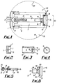
- Fig. 1 shows, in longitudinal section , a fully assembled device according to a first embodiment of the invention.
- This first embodiment is a re-usable device particularly intended to demonstrate the operational principles of the present invention (as distinct from the other embodiments which are single-use devices intended to be disposed of along with the singe-use disposable beverage cans in which they are incorporated).
- the device as shown in Fig. 1 has an end cap (see also Fig. 2) having an axial inlet aperture 5 countersunk at 7 to act as the valve seat of a poppet inlet valve assembly 3.
- the end cap 1 is threaded on an internal surface 10 to co-operate with a corresponding external thread on a wall 13 of a reservoir or internal chamber 9 of the device (see also Fig.s 3 and 4).
- a male part 20 of the inlet valve assembly 3 (see also Fig. 5) is provided as the movable closure element thereof.
- One end 22 of the part 20 is conically shaped to be complementary to the valve seat 7 of the valve assembly 3 and normally cooperates with the valve seat 7 to close the inlet aperture 5.
- the other end of the male part or closure element 20 has a cavity 25 adapted to receive a spring 27 and one end 30 of a spacer bar 35.
- the end 30 of the spacer bar 35 comprises an axial bore 38 which cooperates with the cavity 25 in the closure element 20 to enclose the spring 27 which biases the closure element 20 firmly against the valve seat 7 of the inlet valve assembly 3, thus closing the valve's inlet aperture 5.
- the other end 40 of the spacer bar 35 comprises a second axial bore 45 (Fig. 5), of shorter length than the bore 38, and which accommodates one end 50 of a piston extension 55 of a piston assembly 51 (Figs. 1 and 6).
- the other end 65 of the piston extension 55 has an annular groove 70 and extends from a piston 75 into which is cut a second annular groove 80.
- the piston 75 is of a larger diameter than the piston extension 55 and hence the outward-facing area A2 of the piston 75 (see Fig. 6) substantially exceeds the inward-facing area Al of the piston extension 55. (The functional significance of this area ratio will be explained below).
- Fig. 1 The device of Fig. 1 is assembled as follows:
- the piston extension 55 is inserted into the reservoir 9 through the aperture 15 such that the piston 75 fits into a cylindrical end wall portion 17 of the device.
- O-ring seals 85 and 90 are fitted contiguously with annular grooves 70 and 80 and with the walls of the aperture 15 and the cylindrical portion 17 respectively to provide sliding seals therebetween.
- the piston assembly 51, the aperture 15 and the cylindrical port 17 together define an outlet valve assembly 60 for the device of Fig. 1.
- the piston extension 55 is then slotted into the spacer bar axial bore 45.
- the spring 27 is located in the cylinder formed between axial bore 38 in the spacer bar 35 and cavity 25 on the closure element 20 of the poppet valve.
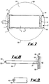
- FIGs. 7, 8 and 9 illustrate a second embodiment of the invention which differs from the first embodiment (described above with reference to Figs. 1-6) in respect of certain details of its construction. (Parts of the second embodiment which are not significantly different from the first embodiment are given the same reference numerals).
- an end cap 1 is welded ultrasonically onto the device body 13 and includes a pliable circumferential ring 2 which presses both ends of the device against the side wall of a beverage can 120 thereby holding the device firmly in position within the can 120.
- a piston assembly 100 of the second embodiment is moulded in a single piece instead of being assembled separately from the separately formed piston 75, spacer bar 35, spring 27 and closure element 20 of the first embodiment.
- the closure element of the inlet valve assembly 3 is provided by a hemispherical protrusion 102 from a hinged plastic spring 103 which provides the force to hold the hemispherical protrusion 102 against the valve seat 7 of the inlet valve assembly 3 thereby closing the inlet aperture 5.
- the O-ring seals 85 and 90 of the first embodiment are replaced in the second embodiment by moulded seals 105 and 110 respectively (Fig. 8), these seals 105 and 110 being formed during the moulding process employed to form the components of the second embodiment to be continuous with the piston assembly 100. Assembly of the second embodiment is analogous to that of the first embodiment, and operation of the second embodiment will be described below along with that of the first embodiment.
- Figs. 10 and 11 illustrate a third embodiment which differs from the first and second embodiments described above in that the inlet valve assembly 3 of the previous embodiments is replaced by a one-way inlet valve 130 as describe in GB1066508 and sometimes known as a "Woodford valve").
- the one-way inlet valve 130 comprises a pliable plastic tube 135 intregal with the end cap 1 and open at each of its ends 135a and 135b.
- One end 135a of the tube 135 has a circular opening 137 therein which presents negligible resistance to the passage of beverage therethrough.
- the other end 135b of the tube 135 comprises a flattened portion 138 of reduced diameter (in comparison to that of 135a) having an opening 139 which consists of a slit in the end 135b of the tube 135, the slit opening 139 being perpendicular to the longitudinal axis of, and in the same plane as the flattened portion 138.
- the third embodiment has a modified outlet valve piston assembly 140 lacking any physical contact with the inlet valve 130 and the single orifice 61 in the wall 13 of the previous embodiments of the device is replaced by four longitudinal exhaust grooves 145 (Fig. 11) on the inner surface of the cylindrical end wall portion 17.
- the device In use of the first or second embodiment of the invention (Figs. 1-6; Figs. 7-9), the device is placed across a diameter of an unmodified beverage can prior to filling, sealing and pasteurisation such that the side wall 120 of the can 119 (Fig. 1; Fig. 7) is in contact with the end cap 1 at one end of the device and in contact with the cylindrical portion 17 at the other end.
- the device is held in position by the force exerted by the pliable circumferential ring (second embodiment only).
- the device is disposed at the bottom of the can 119 throughout the charging and discharging of the device.
- the inlet valve assembly 3 requires a pressure differential of approximately one bar to open.
- the inlet valve assembly 3 opens and beverage flows into the reservoir 9 until the pressure therein increases to a level greater than the pressure in the can minus 1 bar (to account for the bias of the spring 27 or 103) at which point the inlet valve assembly 3 closes.
- the outlet valve assembly 60 has a high external/low internal area ratio that causes it to remain closed at high internal/low external pressure differentials.
- the value of this differential is dependent on the area ratio such that P 1 A 1 ⁇ P 2 A 2 where P 1 and A 1 are the internal pressure and area respectively and P 2 and A 2 are the external pressure and area respectively. Therefore, increases in the pressure differential above the given value result in outward movement of the piston assembly 51 or 100 until the orifice 61 is exposed allowing efflux of beverage therethrough. This efflux continues until the pressure differential is eliminated.
- a generally constant pressure differential is maintained within the reservoir 9, the value of which can be selected by varying the internal/external area ratio of the outlet valve assembly 60.
- the pressure of the beverage in the can 119 decreases very rapidly and this alters the force balance across the outlet valve assembly 60.
- the pressure in the reservoir 9 then causes outward movement of the piston assembly 51 or 100 and exposure of the orifice 61.
- the outward movement of the piston assembly 51 or 100 is restrained by the wall 120 of the can 119 such that the escape of the beverage/gas mixture is through the orifice 61 or the small annular gap in the outlet valve assembly 60 between the chamfered rim 18 of the cylindrical portion 17 and the chamfered rim 82 of the piston assembly 51 or 100. This provides the seed bubbles necessary for head generation in the beverage.
- the device is placed in a can 119 as described for the first and second embodiments.
- the pressure in the can 119 rises due to pasteurisation, beverage flows into the reservoir 9 through the inlet valve 130 until the pressure in the reservoir 9 increases to a level at which the pressure therein equals the pressure in the can minus the small amount of pressure required to open the inlet valve 130, at which point the inflow of beverage stops.
- Increases in the pressure in the reservoir 9 above the pressure in the can cause the walls of the flattened portion 138 to be compressed together thus closing the opening 139 and preventing efflux of beverage through the inlet valve 130.
- the pressure of the beverage in the can 119 decreases very rapidly, upsetting the force balance across the outlet valve assembly 150.
- the pressure in the reservoir 9 then causes outward movement of the piston assembly 140 and allows escape of beverage/gas mixture from the reservoir 9 through the grooves 145.
- the outward movement of the piston assembly 140 is restrained by the wall 120 of the can 119 such that the escaping beverage/gas mixture is forced through the grooves 145 and this initiates the seed bubbles necessary for head generation in the beverage held in the can 119.
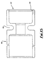
- a fourth embodiment of the foam-generating device of the present invention has an inlet valve 152 of elastomeric material such as rubber.
- the inlet valve 152 is fitted onto one end 155 of the reservoir wall 13.
- a return lip 160 seals the inlet valve 152 onto the wall 13 and this seal is enhanced by the compression applied to the device by the can wall 120.
- the compliance of the valve 152 due to the elastomeric material allows up to a 1% change in the can diameter during thermal cycling without affecting the valve 152.
- the compressive force on the valve 152 is increased by the charge forces on the device causing it to expand.
- the compliance of the valve 152 allows the device to overcome the mechanical changes occurring in charging of the device, and in handling and storage of the filled cans.
- Three reliefs 165 in the face of the inlet valve 152 allow liquid to pass between the valve 152 and the can wall 120.
- Circumferential ribs 170 on the valve 152 are provided to increase resistance to collapse of the valve 152 under pressure when the device is charged.
- Beverage enters the inlet valve 152 through the open end 175 and passes through an orifice in the other end of the valve 152.
- the orifice comprises a slit 180 between two walls of elastomeric material 183,185.
- the slit 180 opens against the compressive force between walls 183 and 185 in response to increase in pressure outside the device and allows influx of fluid.
- the wall 185 is pressed against wall 183 and the slit 180 is closed.
- the valve 180 admits fluid when the external/internal pressure differential across the valve is sufficient to overcome the compressive force of wall 185 against wall 183. Fluid thus admitted cannot escape back through the slit 180 since pressure increases in the device increase the compressive force of wall 185 against wall 183, enhancing the seal on the slit 180.
- the device body 190 (Fig. 15) has an annular groove 192 in the outer surface for assembly, handling and insertion purposes and also for isolating the seal from the flexure of the body 190 when under pressure.
- the body 190 has three longitudinal exhaust grooves 195 in one end 197 for exhaust of pressurised fluid from the device.
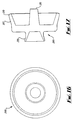
- the fourth embodiment has an outlet valve assembly comprising a differential piston 200 (Figs. 16 and 17) having pressure-energised inner and outer seals 205, 207 which can expand to accommodate the full range of moulding tolerance.
- Inner seal 205 has a cup form whereby fluid pressure on the inner face of the piston 200 will produce a force reaction. Part of the force produced by the internal pressure acts radially to expand the seal 205 and part acts axially to push the piston 200 out of the bore when the device discharges. As the pressure in the device rises, the radial component will increase to form a sealing force which balances the pressure.
- outer seal 207 (which also has a cup form), a lower sealing force is used than in the inner seal 205 to reduce friction and a small chamfer 210 at the rim of the seal 207 is provided to obviate mechanical jamming of the piston 200.
- a protrusion 215 acts as a stroke-limiting end stop for the piston 200 and also provides a convenient pick up point when handling the component thereby reducing handling damage to the seals 205, 207.
- the body 190 and the piston 200 Prior to assembly of the fourth embodiment, the body 190 and the piston 200 are handled by the slot 192 and the protrusion 215 respectively. The components are purged with nitrogen and the piston 200 is then inserted into the body 190, followed by the inlet valve 152. This seals both ends and displaces a proportion of the volume of the device, thereby establishing a positive pressure in the nitrogen. This prevents oxygen ingress and increases the pressure of stored gas to be released in discharge upon the can being opened, thereby enhancing foam-generating performance.
- the fourth embodiment is placed across a diameter of the can 119 and is held in place by the force reaction of the elastomeric inlet valve 152.
- the device admits fluid through the inlet valve 152 when the pressure outside the device is sufficient to open the slit 180 against the force of the wall 185 and the pressure inside the device.
- Beverage (or other gas-containing liquid) is thus admitted into the device and the pressure inside the device increases to a level determined by the internal/external area ratio of the differential piston 200 of the outlet valve as described for previous embodiments.
- the fourth embodiment of device Upon opening of the can, the fourth embodiment of device initiates seed bubbles in accordance with a mechanism similar to that described for the third embodiment.
- the fifth embodiment of device shown is similar to the fourth embodiment, but with an alternative inlet valve 220.
- the inlet valve 220 is constructed from an elastomeric material such as rubber and comprises a diaphragm 225 stretched across one end of the device body 190, the valve 220 having a cross-shaped slit 230 in the centre of the diaphragm 225, a return lip 160, and three inlets 165 as previously described.
- the device is inserted across a diameter of the can and the physical compression of the elastomeric material at the valve 220 creates a force which retains the device in position.
- the diaphragm 225 At pressure equilibrium the diaphragm 225 is distended against the can wall 120 thereby closing and sealing the slit 230 until the pressure outside the device rises due to the pasteurisation process.
- the diaphragm 225 deflects and fluid is admitted through the slit 230, thereby compressing the gas in the reservoir 9.
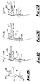
- FIGs. 24 and 25 respectively show a modified version of the outlet valve assembly shown in Figs. 15-17, in its 'closed' configuration, and an enlarged fragmentary view of the valve assembly in its 'open' configuration.
- Figs. 24 and 25 those parts of the modified outlet valve assembly which correspond to parts of the outlet valve assembly of Figs. 15-17 are given the same reference numerals.
Landscapes
- Engineering & Computer Science (AREA)
- Mechanical Engineering (AREA)
- Devices For Dispensing Beverages (AREA)
- Manufacture Of Porous Articles, And Recovery And Treatment Of Waste Products (AREA)
- Processing And Handling Of Plastics And Other Materials For Molding In General (AREA)
- Medicines Containing Antibodies Or Antigens For Use As Internal Diagnostic Agents (AREA)
- Packging For Living Organisms, Food Or Medicinal Products That Are Sensitive To Environmental Conditiond (AREA)
- Distillation Of Fermentation Liquor, Processing Of Alcohols, Vinegar And Beer (AREA)
- Alcoholic Beverages (AREA)
- Non-Alcoholic Beverages (AREA)
Claims (17)
- Vorrichtung zum Erzeugen einer schäumenden Dispersion von Blasen in einem das Äußere der Vorrichtung umgebenden Fluid, welches aus einer Flüssigkeit mit darin gelöstem Gas besteht, wobei die Vorrichtung
dadurch gekennzeichnet ist, daß sie eine innere Kammer aufweist, die mit einer Ventileinrichtung versehen ist, die so ausgebildet ist, daß sie den Zutritt von das Äußere der Vorrichtung umgebendem Fluid durch die Ventileinrichtung und in die Kammer gestattet, wenn der Druck des umgebenden Fluids um einen ersten vorgegebenen Betrag größer ist als der Innendruck der Kammer, wodurch ein Vorrat von unter Druck stehendem Fluid in der Kammer gebildet wird, und wobei die Ventileinrichtung ferner so ausgebildet ist, daß sie den Vorrat von unter Druck stehendem Fluid aus der Kammer freigibt, so daß dieser durch eine Öffnungseinrichtung nach außen in das das Äußere der Vorrichtung umgebenden Fluid austritt, wenn der Innendruck der Kammer um einen zweiten vorgegebenen Betrag größer ist als der Druck des umgebenden Fluids, wobei die Öffnungseinrichtung so dimensioniert ist, daß sie das Ausströmen von Fluid durch sie derart bewirkt, daß eine schäumende Dispersion von Blasen in dem umgebenden Fluid erzeugt wird. - Vorrichtung nach Anspruch 1,
dadurch gekennzeichnet, daß die Öffnungseinrichtung so dimensioniert ist, daß sie eine Entspannung des durch die Öffnungseinrichtung nach außen strömenden Fluids derart bewirkt, daß das in der Flüssigkeit gelöste Gas in Form einer Vielzahl von schaumbildenden Impfblasen aus der Lösung geht. - Vorrichtung nach Anspruch 1 oder 2,
dadurch gekennzeichnet, daß die Ventileinrichtung funktionell getrennte Einlaß- und Auslaßventile aufweist, die jeweils für den Zutritt und für die Freigabe von Fluid zu bzw. aus der Kammer ausgebildet sind. - Vorrichtung nach Anspruch 3,
dadurchgekennzeichnet, daß das Einlaßventil ein Teilerventil ist. - Vorrichtung nach Anspruch 3,
dadurch gekennzeichnet, daß das Einlaßventil ein Rückschlag-Fluidventil, wie in der britischen Patentschrift GB1066508 beschrieben, ist. - Vorrichtung nach Anspruch 3,
dadurch gekennzeichnet, daß das Einlaßventil eine Membran mit mindestens einem darin vorgesehenen Schlitz aufweist, wcbei die Membran die Kammer teilweise umgrenzt und gegenüber einem Fluiddurchtritt nach außen im wesentlichen geschlossen ist, wobei die Membran durch einen äußeren Druck nach innen deformierbar ist, um den mindestens einen Schlitz zu öffnen für den Durchtritt von Fluid durch den Schlitz in die Kammer. - Vorrichtung nach einem der Ansprüche 2 - 6,
dadurch gekennzeichnet, daß das Auslaßventil ein Differentialventil ist. - Vorrichtung nach Anspruch 7,
dadurch gekennzeichnet, daß das Differentialventil die Form eines äußeren Durchlasses hat, der normalerweise geschlossen ist durch einen Pfropfen, der eine der Kammer zugwandte innere Fläche hat, auf die der Innendruck der Kammer wirkt, wobei der Pfropfen ferner eine nach außen gerichtete Außenfläche hat, auf die der Druck des das Äußere der Vorrichtung umgebenden Fluids wirkt, wobei die äußere Fläche um einen solchen Betrag größer als die innere Fläche ist, daß der Auslaßkanal verschlossen gehalten wird, bis der Innendruck der Kammer um den zweiten vorgegebenen Betrag größer ist als der Druck des umgebenden Fluids, wodurch der Auslaßkanal vom Pfropfen freigegeben wird, um den Vorrat von unter Druck stehendem Fluid aus der Kammer freizugeben. - Verfahren zum Erzeugen einer schäumenden Dispersion von Blasen in einem Fluid, welches aus einer Flüssigkeit mit darin gelöstem Gas besteht, wobei das Verfahren
dadurch gekennzeichnet ist, daß eine Vorrichtung nach einem der Ansprüche 1 - 6 vorgesehen wird, das die Vorrichtung in dem Fluid untergetaucht wird, so daß dieses das Äußere der Vorrichtung umgibt, daß das umgebende Fluid unter einen Druck gesetzt wird, der um mindestens den ersten vorgegebenen Betrag größer ist als der Innendruck der Kammer in der Vorrichtung, wodurch ein Teil des umgebenden Fluids durch die Ventileinrichtung der Vorrichtung in die Kammer eingelassen wird, um einen Vorrat von unter Druck stehendem Fluid in der Kammer zu bilden, daß die vorrichtung in dem Fluid eingetaucht gehalten wird und daß das das Äußere der Vorrichtung umgebende Fluid unter einem Druck gehalten wird, der um so viel höher als dessen Anfangsdruck liegt, daß dadurch eine vorzeitige Freigabe eines wesentlichen Teils des Vorrats von unter Druck stehendem Fluids aus der Vorrichtung verhindert wird, wobei das Unterdrucksetzen des umgebenden Fluids aufrechterhalten wird, bis die Erzeugung einer schäumenden Dispersion von Blasen erforderlich wird, und daß dann der Druck des das Äußere der Vorrichtung umgebenden Fluids erniedrigt wird auf einen Druck, der um mindestens den zweiten vorgegebenen Betrag unter dem Innnendruck der Kammer liegt, um den Austritt des Vorrats von Fluid durch die Öffnungseinrichtung zu bewirken, wodurch eine schäumende Dispersion von Blasen in dem umgebenden Fluid erzeugt wird. - Verfahren zum Abpacken eines Getränks in einem verschlossenen Behälter für die spätere Erzeugung einer schäumenden Dispersion von Blasen in dem Getränk beim Öffnen des Bebälters, wobei das Getränk aus einer Flüssigkeit mit darin gelöstem Gas besteht, wobei das Verfahren
gekennzeichnet ist durch die Schritte:Vorsehen eines verschließbaren Behälters, der anfänglich offen und flüssigkeitsleer ist;Vorsehen einer Vorrichtung nach einem der Ansprüche von 1 - 8;Anordnen der Vorrichtung in dem offenen Behälter;Zuführen des Getränks in den offenen Behälter, vor oder nach dem Anordnen der Vorrichtung in dem offenen Behälter, in einer Menge, die ausreicht, die in dem Behälter angeordnete Vorrichtung unterzutauchen und das Äußere der Vorrichtung mit dem Getränk zu umgeben;Verschließen und Abdichten des Behälters mit der darin enthaltenen Menge des Getränks und der untergetauchten Vorrichtung;vorübergehendes Erhöhen der Temperatur mindestens des Inhaltes des verschlossenen und abgedichteten Behälters um einen Betrag derart, daß eine entsprechende Erhöhung des Drucks des die Vorrichtung umgebenden Getränks bewirkt wird, die ausreicht, damit ein Teil des Getränkes durch die Ventileinrichtung der Vorrichtung in die Innenkammer der Vorrichtung eingelassen wird, um einen Vorrat von unter Druck stehendem Getränk in der Kammer zu bilden, so daß beim späteren Öffnen des Behälters das Getränk, welches das Äußere der in dem Behälter angeordneten Vorrichtung umgibt, auf den Druck der umgebenen Atmosphäre entspannt wird und der Druck dieses Getränkes um mindestens den zweiten vorgegebenen Betrag unter den Innnendruck der Kammer der Vorrichtung abfällt aufgrund des darin enthaltenen Getränkevorrats, wodurch die Abgabe des Getränkevorrats aus der Innenkammer der Vorrichtung nach außen durch die Öffnungseinrichtung der Vorrichtung und in das umgebende Getränk hinein ausgelöst wird, um eine schäumende Dispersion von Blasen in dem umgebenden Getränk zu erzeugen, um die Bildung einer Schaumkrone auf dem Getränk zu begünstigen. - Verfahren nach Anspruch 10,
dadurch gekennzeichnet, daß mindestens aus der Innenkammer der Vorrichtung oxidierende Gase ausgetrieben werden, bevor diese in dem Behälter angeordnet wird. - Verfahren nach Anspruch 11,
dadurch gekennzeichnet, daß aus dem Behälter oxidierende Gase ausgetrieben werden, bevor die Menge des Getränks eingefüllt wird. - Verfahren nach einem der Ansprüche 10 - 12,
dadurch gekennzeichnet, daß die vorübergehende Erhöhung der Temperatur mindestens des Inhalts des verschlossenen Behälters Teil eines üblichen Pasteurisierungsvorgangs für frisch verschlossene Getränkebehälter ist. - Verpacktes Getränk,
dadurch gekennzeichnet, daß es einen verschlossenen und abgedichteten Behälter mit einer darin enthaltenen Getränkemenge und einer Vorrichtung nach einem der Ansprüche 1 - 8 aufweist, wobei das Getränk in dem Behälter nach dem Verfahren gemäß einem der Ansprüche 10 - 13 abgepackt ist. - Abgepacktes Getränk nach Anspruch 14,
dadurch gekennzeichnet, daß das Getränk ein alkoholisches Getränk ist. - Abgepacktes Getränk nach Anspruch 15,
dadurch gekennzeichnet, daß das alkoholische Getränk ein durch Gärung erhaltenes Getränk ist, welches gelöstes Kohlendioxid als Gärungsprodukt enthält. - Verpacktes Getränk nach einem der Ansprüche 14 - 16,
dadurch gekennzeichnet, daß der Behälter eine Dose mit einem einstückigen Körper aus tiefgezogenem Aluminium oder Stahl ist, der durch eine anfänglich getrennte Deckelscheibe ebenfalls aus Aluminium oder Stahl verschlossen ist, die eine einstückige Verschlußlasche aufweist, die durch eine Prägung der Deckelscheibe definiert ist und mit einem von Hand betätigbaren Zugring verbunden ist für die teilweise oder vollständige Trennung der Lasche von der Deckelscheibe, um die gefüllte Dose zu Öffnen, wobei das Verschließen und Abdichtan der Dose durch Bördeln der Deckelscheibe an den Rand des Körpers erfolgt.
Applications Claiming Priority (7)
| Application Number | Priority Date | Filing Date | Title |
|---|---|---|---|
| GB919123451A GB9123451D0 (en) | 1991-11-05 | 1991-11-05 | Packaging for beverages |
| GB9123451 | 1991-11-05 | ||
| GB919126702A GB9126702D0 (en) | 1991-12-17 | 1991-12-17 | Package for beverages |
| GB9126702 | 1991-12-17 | ||
| GB929206483A GB9206483D0 (en) | 1992-03-25 | 1992-03-25 | Packaging for beverages |
| GB9206483 | 1992-03-25 | ||
| PCT/GB1992/002048 WO1993009055A1 (en) | 1991-11-05 | 1992-11-05 | Foam generation by dispersion of bubbles |
Publications (2)
| Publication Number | Publication Date |
|---|---|
| EP0610312A1 EP0610312A1 (de) | 1994-08-17 |
| EP0610312B1 true EP0610312B1 (de) | 1998-08-05 |
Family
ID=27265912
Family Applications (1)
| Application Number | Title | Priority Date | Filing Date |
|---|---|---|---|
| EP92922253A Expired - Lifetime EP0610312B1 (de) | 1991-11-05 | 1992-11-05 | Schaumbildung durch blasendispersion |
Country Status (8)
| Country | Link |
|---|---|
| EP (1) | EP0610312B1 (de) |
| JP (1) | JPH07500797A (de) |
| AT (1) | ATE169284T1 (de) |
| AU (1) | AU2890692A (de) |
| CA (1) | CA2122737A1 (de) |
| DE (1) | DE69226533D1 (de) |
| HU (1) | HUT67660A (de) |
| WO (1) | WO1993009055A1 (de) |
Families Citing this family (11)
| Publication number | Priority date | Publication date | Assignee | Title |
|---|---|---|---|---|
| JPH08512011A (ja) * | 1993-06-18 | 1996-12-17 | フィットブレッド ピーエルシー | 発泡促進挿入物を有する容器 |
| GB9312677D0 (en) * | 1993-06-18 | 1993-08-04 | Pyxis Limited | Beverage container and method of producting a filled beverage container |
| ES2109713T3 (es) * | 1993-08-12 | 1998-01-16 | Whitbread & Co Ltd | Envase para bebida carbonica. |
| SG42972A1 (en) * | 1993-08-12 | 1997-10-17 | Heineken Tech Services | Beverage container |
| US5827555A (en) * | 1993-09-28 | 1998-10-27 | American National Can Company | Foaming insert for a beverage container |
| CA2178741C (en) * | 1993-09-28 | 2005-08-16 | Nicholas Adrian Thorne | Foaming insert for a beverage container |
| US5705210A (en) * | 1994-01-21 | 1998-01-06 | Whitbread Plc | Deformable insert for a beverage container |
| WO1995019925A1 (en) * | 1994-01-21 | 1995-07-27 | Whitbread Plc | Beverage container |
| US7228789B1 (en) | 1999-05-18 | 2007-06-12 | Whitbread Plc | Beverage container |
| EP1055614A1 (de) * | 1999-05-18 | 2000-11-29 | Whitbread Plc | Getränkebehälter |
| JP6932445B2 (ja) * | 2017-07-31 | 2021-09-08 | 株式会社吉野工業所 | 発泡用ウィジェット |
Family Cites Families (2)
| Publication number | Priority date | Publication date | Assignee | Title |
|---|---|---|---|---|
| GB1266351A (de) * | 1969-01-27 | 1972-03-08 | ||
| GB2222570A (en) * | 1988-09-12 | 1990-03-14 | Guinness Son & Co Ltd A | Carbonated beverage container |
-
1992
- 1992-11-05 DE DE69226533T patent/DE69226533D1/de not_active Expired - Lifetime
- 1992-11-05 WO PCT/GB1992/002048 patent/WO1993009055A1/en not_active Ceased
- 1992-11-05 AU AU28906/92A patent/AU2890692A/en not_active Abandoned
- 1992-11-05 CA CA002122737A patent/CA2122737A1/en not_active Abandoned
- 1992-11-05 HU HU9401203A patent/HUT67660A/hu unknown
- 1992-11-05 JP JP5508280A patent/JPH07500797A/ja active Pending
- 1992-11-05 EP EP92922253A patent/EP0610312B1/de not_active Expired - Lifetime
- 1992-11-05 AT AT92922253T patent/ATE169284T1/de not_active IP Right Cessation
Also Published As
| Publication number | Publication date |
|---|---|
| EP0610312A1 (de) | 1994-08-17 |
| AU2890692A (en) | 1993-06-07 |
| JPH07500797A (ja) | 1995-01-26 |
| HU9401203D0 (en) | 1994-09-28 |
| CA2122737A1 (en) | 1993-05-13 |
| HUT67660A (en) | 1995-04-28 |
| WO1993009055A1 (en) | 1993-05-13 |
| DE69226533D1 (de) | 1998-09-10 |
| ATE169284T1 (de) | 1998-08-15 |
Similar Documents
| Publication | Publication Date | Title |
|---|---|---|
| EP0502059B1 (de) | Behälter für kohlensäurehaltige getränke | |
| EP0668836B1 (de) | Behälter für kohlensäurehaltige getränke sowie verfahren zu dessen herstellung | |
| AU682431B2 (en) | Beverage container | |
| US4892230A (en) | Carbonated beverage bottle | |
| US5110014A (en) | Bi-stable pressure maintaining gas containers | |
| EP0610312B1 (de) | Schaumbildung durch blasendispersion | |
| JPH0680145A (ja) | 飲料用パッケージ及び飲料をパッケージする方法 | |
| US5667832A (en) | Method and device for foam generation by dispersion of bubbles | |
| GB2279056A (en) | An insert for a beverage container | |
| EP0711242A1 (de) | Getränkebehälter | |
| AU674762B2 (en) | Container with head enhancing insert | |
| GB2272199A (en) | Beverage package | |
| US20020017082A1 (en) | Method for packaging a liquid filled container and a capsule therefore | |
| EP0720575B1 (de) | Getränkedose mit vorrichtung zur schaumerzeugung | |
| GB2273693A (en) | Creating a head on a packaged beverage | |
| GB2282792A (en) | Liquid container and method of manufacture thereof. | |
| GB2285792A (en) | Beverage container with insert |
Legal Events
| Date | Code | Title | Description |
|---|---|---|---|
| PUAI | Public reference made under article 153(3) epc to a published international application that has entered the european phase |
Free format text: ORIGINAL CODE: 0009012 |
|
| 17P | Request for examination filed |
Effective date: 19940601 |
|
| AK | Designated contracting states |
Kind code of ref document: A1 Designated state(s): AT BE CH DE DK ES FR GB GR IE IT LI LU MC NL SE |
|
| GRAG | Despatch of communication of intention to grant |
Free format text: ORIGINAL CODE: EPIDOS AGRA |
|
| 17Q | First examination report despatched |
Effective date: 19970602 |
|
| GRAG | Despatch of communication of intention to grant |
Free format text: ORIGINAL CODE: EPIDOS AGRA |
|
| GRAH | Despatch of communication of intention to grant a patent |
Free format text: ORIGINAL CODE: EPIDOS IGRA |
|
| GRAH | Despatch of communication of intention to grant a patent |
Free format text: ORIGINAL CODE: EPIDOS IGRA |
|
| GRAA | (expected) grant |
Free format text: ORIGINAL CODE: 0009210 |
|
| AK | Designated contracting states |
Kind code of ref document: B1 Designated state(s): AT BE CH DE DK ES FR GB GR IE IT LI LU MC NL SE |
|
| PG25 | Lapsed in a contracting state [announced via postgrant information from national office to epo] |
Ref country code: NL Free format text: LAPSE BECAUSE OF FAILURE TO SUBMIT A TRANSLATION OF THE DESCRIPTION OR TO PAY THE FEE WITHIN THE PRESCRIBED TIME-LIMIT Effective date: 19980805 Ref country code: LI Free format text: LAPSE BECAUSE OF FAILURE TO SUBMIT A TRANSLATION OF THE DESCRIPTION OR TO PAY THE FEE WITHIN THE PRESCRIBED TIME-LIMIT Effective date: 19980805 Ref country code: IT Free format text: LAPSE BECAUSE OF FAILURE TO SUBMIT A TRANSLATION OF THE DESCRIPTION OR TO PAY THE FEE WITHIN THE PRE;WARNING: LAPSES OF ITALIAN PATENTS WITH EFFECTIVE DATE BEFORE 2007 MAY HAVE OCCURRED AT ANY TIME BEFORE 2007. THE CORRECT EFFECTIVE DATE MAY BE DIFFERENT FROM THE ONE RECORDED.SCRIBED TIME-LIMIT Effective date: 19980805 Ref country code: GR Free format text: LAPSE BECAUSE OF NON-PAYMENT OF DUE FEES Effective date: 19980805 Ref country code: FR Free format text: LAPSE BECAUSE OF FAILURE TO SUBMIT A TRANSLATION OF THE DESCRIPTION OR TO PAY THE FEE WITHIN THE PRESCRIBED TIME-LIMIT Effective date: 19980805 Ref country code: ES Free format text: THE PATENT HAS BEEN ANNULLED BY A DECISION OF A NATIONAL AUTHORITY Effective date: 19980805 Ref country code: CH Free format text: LAPSE BECAUSE OF FAILURE TO SUBMIT A TRANSLATION OF THE DESCRIPTION OR TO PAY THE FEE WITHIN THE PRESCRIBED TIME-LIMIT Effective date: 19980805 Ref country code: BE Free format text: LAPSE BECAUSE OF FAILURE TO SUBMIT A TRANSLATION OF THE DESCRIPTION OR TO PAY THE FEE WITHIN THE PRESCRIBED TIME-LIMIT Effective date: 19980805 Ref country code: AT Free format text: LAPSE BECAUSE OF FAILURE TO SUBMIT A TRANSLATION OF THE DESCRIPTION OR TO PAY THE FEE WITHIN THE PRESCRIBED TIME-LIMIT Effective date: 19980805 |
|
| REF | Corresponds to: |
Ref document number: 169284 Country of ref document: AT Date of ref document: 19980815 Kind code of ref document: T |
|
| REG | Reference to a national code |
Ref country code: CH Ref legal event code: EP |
|
| REF | Corresponds to: |
Ref document number: 69226533 Country of ref document: DE Date of ref document: 19980910 |
|
| REG | Reference to a national code |
Ref country code: IE Ref legal event code: FG4D |
|
| PG25 | Lapsed in a contracting state [announced via postgrant information from national office to epo] |
Ref country code: SE Free format text: LAPSE BECAUSE OF FAILURE TO SUBMIT A TRANSLATION OF THE DESCRIPTION OR TO PAY THE FEE WITHIN THE PRESCRIBED TIME-LIMIT Effective date: 19981105 Ref country code: LU Free format text: LAPSE BECAUSE OF NON-PAYMENT OF DUE FEES Effective date: 19981105 Ref country code: IE Free format text: LAPSE BECAUSE OF NON-PAYMENT OF DUE FEES Effective date: 19981105 Ref country code: DK Free format text: LAPSE BECAUSE OF FAILURE TO SUBMIT A TRANSLATION OF THE DESCRIPTION OR TO PAY THE FEE WITHIN THE PRESCRIBED TIME-LIMIT Effective date: 19981105 |
|
| PG25 | Lapsed in a contracting state [announced via postgrant information from national office to epo] |
Ref country code: DE Free format text: LAPSE BECAUSE OF FAILURE TO SUBMIT A TRANSLATION OF THE DESCRIPTION OR TO PAY THE FEE WITHIN THE PRESCRIBED TIME-LIMIT Effective date: 19981106 |
|
| EN | Fr: translation not filed | ||
| NLV1 | Nl: lapsed or annulled due to failure to fulfill the requirements of art. 29p and 29m of the patents act | ||
| REG | Reference to a national code |
Ref country code: CH Ref legal event code: PL |
|
| PG25 | Lapsed in a contracting state [announced via postgrant information from national office to epo] |
Ref country code: MC Free format text: LAPSE BECAUSE OF NON-PAYMENT OF DUE FEES Effective date: 19990531 |
|
| PLBE | No opposition filed within time limit |
Free format text: ORIGINAL CODE: 0009261 |
|
| STAA | Information on the status of an ep patent application or granted ep patent |
Free format text: STATUS: NO OPPOSITION FILED WITHIN TIME LIMIT |
|
| 26N | No opposition filed | ||
| REG | Reference to a national code |
Ref country code: IE Ref legal event code: MM4A |
|
| PGFP | Annual fee paid to national office [announced via postgrant information from national office to epo] |
Ref country code: GB Payment date: 20001006 Year of fee payment: 9 |
|
| PG25 | Lapsed in a contracting state [announced via postgrant information from national office to epo] |
Ref country code: GB Free format text: LAPSE BECAUSE OF NON-PAYMENT OF DUE FEES Effective date: 20011105 |
|
| REG | Reference to a national code |
Ref country code: GB Ref legal event code: IF02 |
|
| GBPC | Gb: european patent ceased through non-payment of renewal fee |
Effective date: 20011105 |