EP0610523B1 - Echantillonneur de gaz d'échappement et système de commande - Google Patents
Echantillonneur de gaz d'échappement et système de commande Download PDFInfo
- Publication number
- EP0610523B1 EP0610523B1 EP93101947A EP93101947A EP0610523B1 EP 0610523 B1 EP0610523 B1 EP 0610523B1 EP 93101947 A EP93101947 A EP 93101947A EP 93101947 A EP93101947 A EP 93101947A EP 0610523 B1 EP0610523 B1 EP 0610523B1
- Authority
- EP
- European Patent Office
- Prior art keywords
- flow rate
- flow
- dilution air
- exhaust
- mixture
- Prior art date
- Legal status (The legal status is an assumption and is not a legal conclusion. Google has not performed a legal analysis and makes no representation as to the accuracy of the status listed.)
- Expired - Lifetime
Links
- 238000010790 dilution Methods 0.000 claims description 68
- 239000012895 dilution Substances 0.000 claims description 68
- 238000005070 sampling Methods 0.000 claims description 56
- 239000000203 mixture Substances 0.000 claims description 51
- 238000011144 upstream manufacturing Methods 0.000 claims description 30
- 238000006073 displacement reaction Methods 0.000 claims description 3
- 239000000523 sample Substances 0.000 description 77
- 239000007789 gas Substances 0.000 description 27
- 230000001276 controlling effect Effects 0.000 description 15
- 238000012360 testing method Methods 0.000 description 10
- 239000012530 fluid Substances 0.000 description 7
- 239000000470 constituent Substances 0.000 description 5
- 239000012470 diluted sample Substances 0.000 description 5
- 238000000034 method Methods 0.000 description 5
- 238000002485 combustion reaction Methods 0.000 description 4
- 238000002156 mixing Methods 0.000 description 4
- 238000012937 correction Methods 0.000 description 2
- 238000005259 measurement Methods 0.000 description 2
- 230000010349 pulsation Effects 0.000 description 2
- 230000003068 static effect Effects 0.000 description 2
- UGFAIRIUMAVXCW-UHFFFAOYSA-N Carbon monoxide Chemical compound [O+]#[C-] UGFAIRIUMAVXCW-UHFFFAOYSA-N 0.000 description 1
- 238000009530 blood pressure measurement Methods 0.000 description 1
- 238000009529 body temperature measurement Methods 0.000 description 1
- 229910002091 carbon monoxide Inorganic materials 0.000 description 1
- 239000003610 charcoal Substances 0.000 description 1
- 238000010276 construction Methods 0.000 description 1
- 239000000356 contaminant Substances 0.000 description 1
- 239000012809 cooling fluid Substances 0.000 description 1
- 230000008878 coupling Effects 0.000 description 1
- 238000010168 coupling process Methods 0.000 description 1
- 238000005859 coupling reaction Methods 0.000 description 1
- 238000011161 development Methods 0.000 description 1
- 230000000694 effects Effects 0.000 description 1
- 239000000284 extract Substances 0.000 description 1
- 238000000605 extraction Methods 0.000 description 1
- 229930195733 hydrocarbon Natural products 0.000 description 1
- 150000002430 hydrocarbons Chemical class 0.000 description 1
- 238000012986 modification Methods 0.000 description 1
- 230000004048 modification Effects 0.000 description 1
- 238000011045 prefiltration Methods 0.000 description 1
- 230000001105 regulatory effect Effects 0.000 description 1
- 239000012898 sample dilution Substances 0.000 description 1
Images


Classifications
-
- G—PHYSICS
- G01—MEASURING; TESTING
- G01N—INVESTIGATING OR ANALYSING MATERIALS BY DETERMINING THEIR CHEMICAL OR PHYSICAL PROPERTIES
- G01N33/00—Investigating or analysing materials by specific methods not covered by groups G01N1/00 - G01N31/00
- G01N33/0004—Gaseous mixtures, e.g. polluted air
- G01N33/0009—General constructional details of gas analysers, e.g. portable test equipment
- G01N33/0011—Sample conditioning
- G01N33/0016—Sample conditioning by regulating a physical variable, e.g. pressure or temperature
-
- G—PHYSICS
- G01—MEASURING; TESTING
- G01N—INVESTIGATING OR ANALYSING MATERIALS BY DETERMINING THEIR CHEMICAL OR PHYSICAL PROPERTIES
- G01N1/00—Sampling; Preparing specimens for investigation
- G01N1/02—Devices for withdrawing samples
- G01N1/22—Devices for withdrawing samples in the gaseous state
- G01N1/2247—Sampling from a flowing stream of gas
- G01N1/2252—Sampling from a flowing stream of gas in a vehicle exhaust
-
- G—PHYSICS
- G01—MEASURING; TESTING
- G01N—INVESTIGATING OR ANALYSING MATERIALS BY DETERMINING THEIR CHEMICAL OR PHYSICAL PROPERTIES
- G01N33/00—Investigating or analysing materials by specific methods not covered by groups G01N1/00 - G01N31/00
- G01N33/0004—Gaseous mixtures, e.g. polluted air
- G01N33/0006—Calibrating gas analysers
-
- G—PHYSICS
- G01—MEASURING; TESTING
- G01N—INVESTIGATING OR ANALYSING MATERIALS BY DETERMINING THEIR CHEMICAL OR PHYSICAL PROPERTIES
- G01N1/00—Sampling; Preparing specimens for investigation
- G01N1/02—Devices for withdrawing samples
- G01N1/22—Devices for withdrawing samples in the gaseous state
- G01N1/24—Suction devices
-
- G—PHYSICS
- G01—MEASURING; TESTING
- G01N—INVESTIGATING OR ANALYSING MATERIALS BY DETERMINING THEIR CHEMICAL OR PHYSICAL PROPERTIES
- G01N1/00—Sampling; Preparing specimens for investigation
- G01N1/28—Preparing specimens for investigation including physical details of (bio-)chemical methods covered elsewhere, e.g. G01N33/50, C12Q
- G01N1/38—Diluting, dispersing or mixing samples
Definitions
- This invention relates to an improved exhaust sampler and control means, and more particularly to an apparatus for measuring the gaseous constituents of exhaust utilizing means for measuring the exhaust or exhaust/air mixture flow including a calibrated subsonic venturi, and means for controlling the flow rate of dilution air or exhaust/air mixture.
- the general scheme of such testing is to add dilution air to the exhaust gases.
- the total volume of the mixture of exhaust and dilution air must be measured.
- a continuously proportional sample of volume must be collected and is stored for subsequent analysis of constituents such as hydrocarbons, carbon monoxide, and NO x . Mass emissions are determined from the sample concentrations and total flow over the test period.
- Another system utilizes a pair of critical flow venturis for proportional sampling.
- An example of such a system is set forth in U.S. Patent 3,817,100.
- a downstream pump produces a sufficient vacuum on the bulkstream critical flow venturi exit so that the bulkstream mixture is flowing at sonic velocity, a condition which limits the bulkstream mixture to a constant mass flow rate at a given set of upstream temperature and pressure conditions measured at the bulkstream critical flow venturi inlet.
- a sample is extracted from the dilute bulkstream flow through another critical flow venturi in close proximity to the bulkstream critical flow venturi so that the venturis are operating under the same inlet pressure and temperature conditions.
- This sample critical flow venturi operates in connection with a downstream pump in the sampling line to create sonic flow, and thereby a constant mass flow rate at the measured upstream temperature and pressure conditions.
- the sample critical flow venturi extracts a sample for analysis at a flow rate proportional to the bulkstream flow rate.
- an apparatus for sampling the emission content of exhaust from an exhaust source which comprises an exhaust inlet adapted for connection with the exhaust source, a dilution air inlet adapted for connection with said exhaust inlet to provide a mixture of exhaust and dilution air, means for defining a flow confining path for the mixture, flow control means coupled with said flow confining path for establishing a flow of said mixture in said flow confining path, means for measuring the flow rate of said mixture including a venturi restriction, a sampling zone located in said flow confining path upstream of said venturi restriction, and means for extracting a sample of the mixture flowing through said sampling zone including means defining a sample flow path.
- this known apparatus uses a critical venturi restriction to control the flow rate of the bulkstream mixture and does not provide for active control of the bulkstream of sample flow rates to allow static and dynamic sampling of the bulkstream mixture.
- an object of the invention to provide an apparatus for sampling the emission content of exhaust from an exhaust source wherein a wide variety of flow rates may be selected and controlled between or during the test phases.
- an apparatus shall be provided for sampling the emission content of exhaust from an exhaust source having a constant flow rate operating mode and a variable flow operating mode that provides a means for maintaining a constant dilution ratio with changing bulkstream or exhaust flow rate.
- this object is achieved by designing an apparatus as known from EP-A-0 155 793 by providing controller means responsive to the measuring means for controlling the flow control means so as to create a predetermined mass flow rate of the mixture at subsonic velocity through said sampling zone related to said preselected constant mass flow rate of said extracted sample, thereby operating said venturi restriction as a subsonic venturi restriction.
- means for measuring the flow rate of the mixture which comprises a subsonic venturi restriction, means for measuring at least one condition of the mixture upstream of the subsonic venturi, preferably the pressure and temperature of the mixture upstream of the subsonic venturi, means for measuring a condition, preferably the pressure, of the mixture in the throat of the subsonic venturi and a control unit for computing the flow rate of the mixture based on signals received from the upstream measuring means and from the subsonic venturi measuring means.
- the sampling apparatus further comprises means for controlling the flow rate of the mixture in response to the computed flow rate of the mixture, means for extracting a sample of the mixture and means for controlling the flow rate of the extracted sample.
- an apparatus for sampling the emission content of exhaust from an exhaust source which comprises an exhaust inlet adapted for connection with the exhaust source, means for defining a flow confining path for the exhaust and means coupled with the exhaust flow confining path for establishing a flow in the exhaust flow confining path.
- means for measuring the flow rate of the exhaust comprising a subsonic venturi restriction, means for measuring at least one condition, preferably both pressure and temperature, of the exhaust upstream of the subsonic venturi, means for measuring a condition such as pressure of the exhaust in the subsonic venturi and a control unit for computing the flow rate of the exhaust based on signals received from the upstream and subsonic venturi measuring means.
- the apparatus further includes means for controlling the flow rate of the exhaust in response to the computed flow rate of the exhaust and means for extracting a sample of the exhaust which comprises a sample flow confining path.
- Means coupled to the sample flow confining path is provided for supplying dilution gas to the sample to provide a mixture of exhaust sample and dilution gas.
- the invention includes means for controlling the flow rate of the dilution gas in response to signals received from the control unit and means for controlling the flow rate of the mixture in response to signals received from the control unit.
- an apparatus for sampling the emission content of exhaust from an exhaust source comprising an exhaust inlet adapted for connection with the exhaust source, means for defining a flow confining path for the exhaust, and means coupled with the exhaust flow confining path for establishing a flow therein.
- Means are provided for measuring the flow rate of the exhaust comprising a subsonic venturi restriction, means for measuring at least one condition, preferably both pressure and temperature, of the exhaust upstream of the subsonic venturi, means for measuring a condition such as pressure of the exhaust in the subsonic venturi and a control unit for computing the flow rate of the exhaust based on signals received from the upstream and subsonic venturi measuring means.
- the sampling apparatus further comprises means for extracting a sample of the exhaust which includes a sample flow confining path.
- means are provided for controlling the sample flow rate in response to signals received from the control unit.
- Figure 1 is a diagrammatic illustration of an exhaust sampling system constructed similiar to the invention.
- Figure 2 is a diagrammatic illustration of another exhaust sampling system showing another embodiment similiar to the invention.
- Figure 3 is a diagrammatic illustration of an exhaust sampling system showing another embodiment similiar to the invention.
- Figure 4 is a diagrammatic illustration of an exhaust sampling system showing another embodiment similiar to the invention.
- Figure 5 is a diagrammatic illustration of an exhaust sampling system showing a first embodiment of the invention.
- Figure 6 is a diagrammatic illustration of an exhaust sampling system showing a second embodiment of the invention.
- Figure 7 is a diagrammatic illustration of an exhaust sampling system showing a third embodiment of the invention.
- Figure 8 is a diagrammatic illustration of an exhaust sampling system showing a sampling apparatus wherein a flow straightener or heat exchanger is positioned upstream of the subsonic venturi restriction.
- the flow straightener or heat exchanger are applicable to all embodiments of the invention.
- Figure 9 is a diagrammatic illustration of an exhaust sampling system showing a sampling apparatus wherein a variable speed blower is positioned between the dilution air subsonic venturi and dilution air filter assembly. This arrangement can be used in connection with the first and second embodiments of the invention.
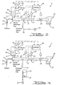
- an apparatus not covered by the current invention for sampling and measuring the emission content of exhaust from a source is depicted and is identified generally by the reference numeral 11.
- the apparatus 11 comprises a tail pipe adapter 12 for coupling to an internal combustion engine exhaust tail pipe 13. Exhaust from the tail pipe 13 is introduced through an exhaust inlet pipe 14 into a mixing duct 15 which is coupled to an air stack 16 that receives ambient inlet air through a filter 17.
- This filter 17 may be implemented using a series of stacked filters such as a pre-filter 18, a charcoal filter 19 and an absolute filter 21.
- Filter assembly 17 serves generally to provide a supply of relatively pollution free inlet air which is mixed in the mixing duct 15 with the exhaust from the internal combustion engine or other exhaust source coupled to the exhaust inlet pipe 14.
- the mixing duct 15 is coupled in a primary fluid defining path or line, designated generally by the reference numeral 22, through which the exhaust/inlet dilution air mixture flows.
- a single speed compressor unit or pump 23 is coupled in the primary fluid path 22 and provides vacuum pressure to establish the flow of the mixture, sometimes referred to as the bulkstream flow, in the primary fluid path 22.
- the flow establishing compressor unit or pump 23 vents to the atmosphere through a discharge vent 20.
- the bulkstream flow rate measurement is obtained using a pair of pressure transducers 24 and 25 and a temperature transducer 26 in connection with a calibrated subsonic venturi restriction 27.
- a subsonic venturi restriction 27 if the upstream pressure and temperature of the mixture as well as the pressure at the throat of the subsonic venturi 27 are known, the bulkstream flow rate may then be computed.
- pressure and temperature transducers 24 and 26 are provided upstream of the subsonic venturi restriction 27 in a sampling zone 31 of the primary fluid path 22 for measuring the temperature and pressure respectively of the mixture immediately prior to entering the subsonic venturi 27.
- pressure transducer 25 is provided for measuring the subsonic venturi throat pressure of the mixture.
- transducers 24, 26 and 25 are each electrically connected to a control unit 28 which may be a digital or analog computer and are each adapted to transmit electrical signals to the control unit 28 indicative of the sampling zone 31 pressure and temperature and throat pressure respectively.
- the control unit 28 computes the bulkstream flow rate based on the signals received from these pressure and temperature transducers 24, 25 and 26.
- the flow rates referred to herein with respect to the present invention are mass flow rates.
- this controlling means comprises an adjustable flow control valve 29.
- the flow control valve 29 is electrically connected to the control unit 28 so that it is adjusted automatically in response to the computed flow rate.
- the valve 29 is manually adjusted based on the computed flow rate.
- control unit 28 sends an electrical signal to the flow control valve 29 to adjust the bulkstream flow to create upstream pressure and temperature conditions, as measured by pressure and temperature transducers 24 and 26 respectively, which are substantially equal to the predetermined upstream pressure and temperature conditions which would exist under critical flow conditions. This creates critical flow pressure and temperature conditions in the sampling zone 31.
- the extracted sample flow rate through a sample flow path 33 will be proportional to the bulkstream flow rate, since the inlet pressure and temperature conditions of the extracted sample flow are simultaneously equal to the inlet pressure and temperature conditions of the controlled bulkstream flow.
- the sample critical flow venturi 32 meters the extracted sample flow and is used to control and stabilize the extracted sample flow in the sample line 33, independent of the downstream vacuum, by virtue of sonic flow at the throat of the venturi 32.
- a pump 34 is positioned downstream of the critical flow venturi 32 to provide a sufficient vacuum at the exit of the venturi 32 to maintain sonic or critical flow.
- the flow rate controlled by a critical flow venturi will vary a small amount due to changes in venturi inlet pressure and temperature
- both a sample and a bulkstream critical flow venturi are used and are arranged so that they have identical inlet critical flow rate temperature and pressure conditions
- the upstream inlet temperature and pressure variations will affect each in the same manner so that the sample flow rate will be extracted proportional to the bulkstream flow rate.
- the sampling apparatus of this embodiment allows for active control of the bulkstream flow rate to simulate the flow control of a critical flow venturi, thus allowing the use of the sample critical flow venturi 32 for proportional sampling.
- control valve 29 may be eliminated if a variable speed compressor, turbocompressor, or variable speed positive displacement pump is used as the flow establishing means in place of the single speed compressor or pump 23.
- the variable speed pump, compressor or turbocompressor preferably will be electrically connected to the control unit 28 so that the variable speed pump, compressor or turbocompressor is automatically adjusted in response to the computed flow rate. This arrangement is applicable to all embodiments.
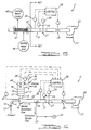
- FIGS 2 through 8 diagrammatically illustrate alternative apparatuses for sampling the emission content of exhaust from an exhaust source which are constructed in accordance with additional embodiments of the invention.
- the apparatuses of each of these additional embodiments are generally similar to that described in connection with the afore described embodiment. For that reason, components of these additional embodiments which are the same as components of the first embodiment are identified by the same reference numerals and will not be described again, except insofar as is necessary to understand the construction and operation of these additional embodiments.
- Figure 2 shows another embodiment not covered by the current invention in which the sample critical flow venturi 32 is replaced by a sampling duct coupled to the sample line 33 in the sampling zone 31.
- An adjustable flow control valve 35 and differential pressure regulator 36 are used to regulate or meter the extracted sample flow through sample line 33 at a desired constant flow rate.
- the flow control valve 35 which is used to select a desired flow rate for the extracted sample, establishes a pressure differential between its inlet side and its outlet side. After an extracted sample flow rate is selected, it is held constant by the differential pressure regulator 36 that is coupled with sample fluid path 33 to receive extracted sample flow both upstream and downstream of the flow control valve 35.
- the differential pressure regulator 36 determines the pressure differential between this upstream and downstream flow with respect to the control valve 35 to maintain the pre-selected constant mass flow rate for the extracted sample.
- the bulkstream flow rate is controlled by the subsonic venturi restriction 27 and flow control valve 29 to maintain a constant ratio of the extracted sample flow rate to the bulkstream flow rate during the testing period.
- the sample flow rate is proportional to the bulkstream flow rate, allowing for proportional sampling.
- FIG. 3 another embodiment of an exhaust sampling apparatus not covered by the current invention is depicted wherein the exhaust flow rate may be directly determined, and the sample is extracted using the critical flow venturi 32.
- the apparatus of this embodiment contains all of the components of that of the first described embodiment, and in addition includes a calibrated subsonic venturi restriction 37 for the dilution air.
- This subsonic venturi 37 is coupled to the air stack 16 as shown in Figure 3 and acts to meter the inlet dilution air flow rate.
- the external dilution air temperature is measured by a temperature transducer 38 and the dilution air pressure is measured at the throat of the venturi 37 by a pressure transducer 39.
- transducers 38 and 39 transmit their respective signals to the control unit 28 where they are processed.
- the bulkstream flow rate is computed as described in connection with the first described embodiment and the exhaust flow rate is calculated as the bulkstream flow rate less the dilution air flow rate.
- Adjustable flow control valve 29 is used to adjust the bulkstream flow rate to maintain conditions simulating the performance of a critical flow venturi.
- the extracted sample flow rate through the critical flow venturi 32 may be determined by the pressure and temperature measurements taken by transducers 24 and 26 in sampling zone 31.
- the integrated bag sample volume analyzed concentration can then be corrected by control unit 28 to account for variations in the bulkstream flow rate during the test period to provide a correlation to the results that would be obtained using the critical flow venturi test equipment described in the aforementioned Kaufman patent.
- Figure 4 diagrammatically shows another embodiment of the sampling apparatus wherein a constant ratio of dilution air flow rate to exhaust flow rate is maintained and the sample is extracted at a fixed mass flow rate.
- This embodiment utilizes the flow control valve 35 and differential pressure regulator 36 of Fig. 2 to provide the fixed mass flow rate for the extracted sample, eliminating the critical flow venturi 32 and the need for pressure and temperature corrections with respect thereto.
- this embodiment has the capability of easily selecting a fixed sample flow rate for special tests.
- this embodiment also incorporates the dilution air flow rate measurement equipment of the fourth embodiment, as well as the control features of that embodiment to adjust the bulkstream flow rate to maintain a fixed ratio of dilution air to exhaust flow rates.
- a sampling apparatus which provides for active control of the ratio of dilution air to exhaust flow rates with proportional sample flow rate control.
- a mass flow meter 41 is positioned in the sample line 33 for measuring and controlling the mass flow rate therethrough and for receiving an electrical signal from the control unit 28 to provide sample flow rate adjustment.
- a filter 42 is located in the sample path 33 upstream of the mass flow meter 41 to remove particulates and prevent them from contaminating the flow meter 41.
- the sample flow rate may be controlled by mass flow meter 41 so that it is proportional to the bulkstream flow rate as determined using the subsonic venturi 27.
- the sample flow rate may be controlled to simulate an integrated volume similar to the critical flow venturi equipment described in Kaufman.
- Another alternative is to maintain a pre-selected, constant sample flow rate.
- a second embodiment of the invention which involves raw exhaust sample extraction with extracted sample dilution control.
- the air stack 16 and associated components are eliminated.
- a dry gas supply line identified by the reference numeral 43, is coupled to the sample line 33 upstream of the mass flow meter 41 and filter 42.
- Another mass flow meter 44 is coupled in the dry gas supply line 43 for regulating the mass flow rate of the dry gas which is used to dilute the extracted raw exhaust sample.
- the diluted sample flow rate through sample line 33 is controlled by mass flow meter 41 as described with reference to Figure 5.
- the dry gas mass flow meter 44 receives an electrical signal from the control unit 28 for active control of the dry gas flow rate.
- Flow control valve 29 is adjusted by the control unit 28 to maintain the pressure in the sampling zone 31, as measured by pressure transducer 24, at zero value so that the flow rate measured using the subsonic venturi 27 is the exhaust flow rate.
- Active control of the dry gas flow rate by mass flow meter 44 and active control of the extracted diluted sample flow rate by mass flow meter 41 allows two methods of obtaining a proportional diluted sample. The first involves a fixed dilution ratio, wherein the extracted diluted sample flow rate and dry gas flow rate are controlled proportionately to the exhaust flow rate to maintain a constant dilution ratio of dry gas flow rate to exhaust flow rate.
- the extracted diluted sample flow rate is set at a fixed value.
- the dry gas flow rate is adjusted by the control unit 28 so that the dry gas flow rate is inversely proportional to the exhaust flow rate, scaled with the extracted sample flow rate.
- the dry gas flow rate equals the extracted sample flow rate.
- the dry gas flow rate equals one-half of the extracted sample flow rate, resulting in a dilution ratio of dry gas flow rate to exhaust flow rate of 1:1.
- FIG. 7 A third embodiment of the invention is shown in Figure 7, which is generally similar to the second embodiment in that the air stack 16 and associated components are not used.
- the sample line 33 may be heated by means of a heater 45 that encloses a portion of the line 33. Coupled to the heater 45 is a temperature regulator 46 for controlling the temperature of the heater 45.
- the dry gas supply line 43 is coupled to the sample line 33 downstream of the mass flow meter 41 which controls the sample flow rate. As in the second embodiment, the mass flow meter 44 regulates the dry gas flow rate.
- a raw exhaust sample is extracted from the exhaust flow through the heated sample line 33 and is filtered by filter 42.
- the two methods for obtaining a proportional sample described in conjunction with the seventh embodiment may then be used.
- the sampling apparatus of the eighth embodiment may be used with or without the heater 45 and accompanying temperature controller 46.
- a sampling apparatus which incorporates a flow straightener identified by the reference numeral 47 is coupled with the primary fluid line 22 upstream of the subsonic venturi 27.
- the flow straightener 47 usually consist of tubing bundled together and contained within a piece of pipe; fluid flows through the bundle of tubing.
- the sampling apparatus may contain a heat exchanger 48 that has an inlet and an outlet so that cooling fluid may be circulated through the tubing to cool the bulkstream flow.
- the flow straightener 47 may be used with all of the described embodiments but is particularly useful for the raw sampling embodiments shown in Figures 6 and 7.
- the flow straightener acts to minimize gas turbulence which may occur under certain operating conditions. Exhaust pulsations usually occur at engine idle settings, and the flow straightener 47 will minimize the pulsations before the flow reaches the subsonic venturi 27.
- the heat exchanger 48 may be used in place of the flow straightener 47 and in addition to straightening the flow will also cool the bulkstream mixture or raw exhaust flow thus reducing the sample temperature changes. This, in turn, will reduce the amount of correction required by the control unit 28.
- an exhaust sampling apparatus which has a variable speed blower or fan 49 positioned between the dilution air subsonic venturi 37 and dilution air filter assembly 17.
- the blower 49 receives electrical signals from the control unit 28 which controls the blower or fan speed to control the dilution air flow rate.
- the blower or fan speed is controlled so that the pressure sensed by a pressure transducer 51 positioned in the mixing duct 15 is maintained at a preset value, usually zero atmospheric pressure, so that the pressure reflected at the vehicle tailpipe 14 sees no effect of the test equipment.
- the system can be arranged so that this control is based on pressure signals of transducer 24 in the sampling zone 31.
- the blower speed may also be controlled, in conjunction with bulkstream flow rate, to obtain additional dilution ratios, unattainable with non force-fed dilution air.
Landscapes
- Chemical & Material Sciences (AREA)
- Life Sciences & Earth Sciences (AREA)
- Health & Medical Sciences (AREA)
- Engineering & Computer Science (AREA)
- Pathology (AREA)
- Physics & Mathematics (AREA)
- Analytical Chemistry (AREA)
- Biochemistry (AREA)
- General Health & Medical Sciences (AREA)
- General Physics & Mathematics (AREA)
- Immunology (AREA)
- Combustion & Propulsion (AREA)
- Food Science & Technology (AREA)
- Medicinal Chemistry (AREA)
- Molecular Biology (AREA)
- Biomedical Technology (AREA)
- Sampling And Sample Adjustment (AREA)
Claims (17)
- Appareil pour échantillonner la teneur en émissions d'un échappement sortant d'une source d'échappement comprenant :une entrée d'échappement (14) adaptée pour être raccordée à la source d'échappement ;une entrée d'air de dilution adaptée pour être raccordée à ladite entrée d'échappement (14) de façon à produire un mélange d'échappement et d'air de dilution ;des moyens pour définir un chemin de confinement de flux pour ledit mélange ;des moyens de régulation de flux (23, 29) couplés audit chemin de confinement de flux pour créer un flux dudit mélange dans ledit chemin de confinement de flux ;des moyens pour mesurer le débit dudit mélange et comprenant un rétrécissement de Venturi (27) ;une zone d'échantillonnage (31) située dans ledit chemin de confinement de flux en amont dudit rétrécissement de Venturi (27) ;des moyens (33, 34) pour prélever un échantillon du mélange s'écoulant à travers ladite zone d'échantillonnage (31), comprenant des moyens définissant un chemin de flux d'échantillon (33), dans lesquels lesdits moyens de prélèvement (33, 34) comprennent un débitmètre massique (41) pour réguler le débit massique à travers ledit chemin de flux d'échantillon (33) ;des moyens (32) pour maintenir un débit massique constant présélectionné à travers ledit chemin de flux d'échantillon (33) ;caractérisé en ce qu'il est prévu des moyens formant dispositif de commande (28) réagissant auxdits moyens de mesure pour commander lesdits moyens de régulation de flux (23, 29) de façon à créer un débit massique prédéterminé dudit mélange à une vitesse subsonique à travers ladite zone d'échantillonnage (31), associé audit débit massique constant présélectionné dudit échantillon prélevé, ce qui fait fonctionner ledit rétrécissement de Venturi comme un rétrécissement de Venturi subsonique (27).
- Appareil selon la revendication 1, caractérisé en ce que lesdits moyens formant dispositif de commande (28) sont adaptés pour maintenir un rapport constant entre le débit massique dudit mélange à travers ladite zone d'échantillonnage (31) et le débit massique constant présélectionné à travers ledit chemin de flux d'échantillon (33).
- Appareil selon l'une quelconque des revendications 1 ou 2, caractérisé en ce que lesdits moyens de mesure comprennent des moyens transducteurs (24, 25, 26) pour produire des signaux proportionnels à une caractéristique dudit mélange en amont dudit rétrécissement de Venturi subsonique et à une caractéristique dudit mélange dans ledit rétrécissement de Venturi subsonique (27).
- Appareil selon l'une quelconque des revendications 1 à 3, caractérisé en ce que ledit débitmètre massique (41) est adapté pour recevoir un signal de commande provenant desdits moyens formant dispositif de commande (28) pour réguler le flux à travers ledit chemin de flux d'échantillon (33).
- Appareil selon l'une quelconque des précédentes revendications, caractérisé en ce que lesdits moyens de régulation de flux comprennent une pompe à débit fixe (23) pour créer un flux de mélange.
- Appareil selon la revendication 5, caractérisé en ce que lesdits moyens de régulation de flux comprennent une vanne réglable (29) pour réguler le débit du mélange, positionnée en aval dudit venturi subsonique (27) et en amont de ladite pompe à débit fixe (23).
- Appareil selon l'une quelconque des précédentes revendications, caractérisé en ce que lesdits moyens de création de flux de mélange (23) et lesdits moyens de régulation de débit de mélange (29) comprennent un compresseur à vitesse variable.
- Appareil selon l'une quelconque des précédentes revendications, caractérisé en ce que lesdits moyens de création de flux de mélange (23) et lesdits moyens de régulation de débit de mélange (29) comprennent une pompe volumétrique à vitesse variable.
- Appareil selon l'une quelconque des précédentes revendications, caractérisé en ce qu'il comprend des moyens (44) pour réguler le débit du gaz de dilution en réponse à des signaux reçus desdits moyens formant dispositif de commande (28).
- Appareil selon l'une quelconque des précédentes revendications, caractérisé en ce qu'il comprend un rétrécissement de Venturi subsonique (37) couplé à ladite entrée d'air, des moyens (38) pour mesurer la température de l'air de dilution en amont dudit venturi subsonique d'air de dilution (37) et des moyens (39) pour mesurer la pression de l'air de dilution dans ledit venturi subsonique d'air de dilution (37), le débit dudit mélange étant régulé de façon à maintenir des conditions simulant les performances d'un venturi à écoulement critique.
- Appareil selon l'une quelconque des revendications 1 à 9, caractérisé en ce qu'il comprend des moyens pour mesurer le débit de l'air de dilution comprenant un rétrécissement de Venturi subsonique (37) couplé à ladite entrée d'air, des moyens (38) pour mesurer la température de l'air de dilution en amont dudit venturi subsonique d'air de dilution (37) et des moyens (39) pour mesurer la pression de l'air de dilution dans ledit venturi subsonique d'air de dilution (37), le débit dudit mélange étant régulé de façon à maintenir un rapport fixe entre le débit d'air de dilution et le débit d'échappement.
- Appareil selon les revendications 1 à 11, caractérisé en ce que le débit de l'échantillon prélevé et le débit de gaz de dilution sont régulés de façon qu'ils soient proportionnels au débit d'échappement de manière à maintenir un rapport de dilution constant entre le débit de gaz de dilution et le débit de gaz d'échappement.
- Appareil selon l'une quelconque des revendications 1 à 12, caractérisé en ce que le débit de l'échantillon prélevé est réglé à une valeur constante et en ce que le débit de gaz de dilution est régulé de façon qu'il soit inversement proportionnel au débit d'échappement, pondéré avec le débit de l'échantillon prélevé.
- Appareil selon l'une quelconque des précédentes revendications, caractérisé en ce que ledit chemin de confinement de flux comprend un redresseur de flux (47) en amont dudit venturi subsonique (27).
- Appareil selon l'une quelconque des précédentes revendications, caractérisé en ce que ledit chemin de confinement de flux comprend un échangeur de chaleur (48) en amont dudit venturi subsonique (27).
- Appareil selon l'une quelconque des précédentes revendications, caractérisé en ce qu'il comprend des moyens pour mesurer le débit de l'air de dilution comprenant un rétrécissement de Venturi subsonique (37) couplé à ladite entrée d'air, des moyens (38) pour mesurer la température de l'air de dilution en amont dudit venturi subsonique d'air de dilution (37) et des moyens (39) pour mesurer la pression de l'air de dilution dans ledit venturi subsonique d'air de dilution (37), ainsi que des moyens pour réguler le débit de l'air de dilution comprenant un ventilateur (49) positionné en aval dudit venturi subsonique d'air de dilution (37) et un transducteur de pression (51) pour mesurer la pression du mélange, le débit de l'air de dilution étant régulé de façon à maintenir une pression prédéfinie telle que mesurée par ledit transducteur de pression (51).
- Appareil selon l'une quelconque des revendications 1 à 15, caractérisé en ce qu'il comprend des moyens pour mesurer le débit de l'air de dilution comprenant un rétrécissement de Venturi subsonique (37) couplé à ladite entrée d'air, des moyens (38) pour mesurer la température de l'air de dilution en amont dudit venturi subsonique d'air de dilution (37) et des moyens (39) pour mesurer la pression de l'air de dilution dans ledit venturi subsonique d'air de dilution (37), ainsi que des moyens pour réguler le débit de l'air de dilution comprenant un ventilateur (49) positionné en aval dudit venturi subsonique d'air de dilution (37) et un transducteur de pression (51) pour mesurer la pression du mélange, le débit de l'air de dilution et le débit dudit mélange étant régulés de façon à maintenir un rapport de dilution fixe entre le débit d'air de dilution et le débit d'échappement et une pression prédéfinie telle que mesurée par ledit transducteur de pression.
Priority Applications (4)
| Application Number | Priority Date | Filing Date | Title |
|---|---|---|---|
| US07/695,606 US5184501A (en) | 1991-05-03 | 1991-05-03 | Exhaust sampler and control means |
| JP4112469A JP2835552B2 (ja) | 1991-05-03 | 1992-05-01 | 排気サンプラーとその制御手段 |
| DE1993626679 DE69326679T2 (de) | 1993-02-08 | 1993-02-08 | Abgasprobennehmer und Steuersystem |
| EP93101947A EP0610523B1 (fr) | 1991-05-03 | 1993-02-08 | Echantillonneur de gaz d'échappement et système de commande |
Applications Claiming Priority (2)
| Application Number | Priority Date | Filing Date | Title |
|---|---|---|---|
| US07/695,606 US5184501A (en) | 1991-05-03 | 1991-05-03 | Exhaust sampler and control means |
| EP93101947A EP0610523B1 (fr) | 1991-05-03 | 1993-02-08 | Echantillonneur de gaz d'échappement et système de commande |
Publications (2)
| Publication Number | Publication Date |
|---|---|
| EP0610523A1 EP0610523A1 (fr) | 1994-08-17 |
| EP0610523B1 true EP0610523B1 (fr) | 1999-10-06 |
Family
ID=26133083
Family Applications (1)
| Application Number | Title | Priority Date | Filing Date |
|---|---|---|---|
| EP93101947A Expired - Lifetime EP0610523B1 (fr) | 1991-05-03 | 1993-02-08 | Echantillonneur de gaz d'échappement et système de commande |
Country Status (3)
| Country | Link |
|---|---|
| US (1) | US5184501A (fr) |
| EP (1) | EP0610523B1 (fr) |
| JP (1) | JP2835552B2 (fr) |
Families Citing this family (68)
| Publication number | Priority date | Publication date | Assignee | Title |
|---|---|---|---|---|
| US5419178A (en) * | 1990-05-14 | 1995-05-30 | Siemens Aktiengesellschaft | Exhaust-gas analyzer |
| US5297432A (en) * | 1991-11-12 | 1994-03-29 | United Sciences, Inc. | Vacuum dilution extraction gas sampling method |
| US5337595A (en) * | 1992-03-18 | 1994-08-16 | Horiba Instruments, Incorporated | Subsonic venturi proportional and isokinetic sampling methods and apparatus |
| US5269659A (en) * | 1992-08-28 | 1993-12-14 | University Corporation For Atmospheric Research | Air sampling pump system |
| US5410907A (en) * | 1993-08-25 | 1995-05-02 | White Consolidated Ind Inc | Gas sampling method and dilution tunnel therefor |
| JPH07260644A (ja) * | 1994-03-26 | 1995-10-13 | Horiba Ltd | ガス分析におけるサンプリング装置 |
| US6058789A (en) * | 1994-03-26 | 2000-05-09 | Kohsaka; Hiroji | Sampling device for gas analyzers |
| DE4437739A1 (de) * | 1994-10-21 | 1996-04-25 | Siemens Ag | Verfahren und Anordnung zum Aufbereiten von Abgas, insbesondere von Verbrennungsmotoren für die Analyse |
| JP3201506B2 (ja) * | 1995-02-21 | 2001-08-20 | 株式会社堀場製作所 | ガスサンプリング装置 |
| DE19523599A1 (de) * | 1995-06-30 | 1997-01-02 | Ruhrgas Ag | Verfahren und Vorrichtung zum Erfassen des Massenstromverlaufs mindestens einer Emissionskomponente eines Verbrennungsabgases |
| DE19631922C2 (de) * | 1995-08-07 | 2003-12-04 | Mitsubishi Motors Corp | Abgasmeßvorrichtung |
| US5596154A (en) * | 1995-09-21 | 1997-01-21 | Enviroplan, Inc. | Dilution control method and apparatus |
| US6200819B1 (en) * | 1995-09-29 | 2001-03-13 | Horiba Instruments, Inc. | Method and apparatus for providing diluent gas to exhaust emission analyzer |
| US5756360A (en) * | 1995-09-29 | 1998-05-26 | Horiba Instruments Inc. | Method and apparatus for providing diluted gas to exhaust emission analyzer |
| US5639957A (en) * | 1995-10-12 | 1997-06-17 | Snap-On Technologies, Inc. | Method and apparatus for performing modal mass analysis of exhaust gas from motor vehicle |
| US5846831A (en) * | 1997-04-01 | 1998-12-08 | Horiba Instuments, Inc. | Methods and systems for controlling flow of a diluted sample and determining pollutants based on water content in engine exhaust emissions |
| US6016711A (en) * | 1997-11-21 | 2000-01-25 | Southwest Research Institute | Mobile vehicle emissions sampling system |
| CA2316158C (fr) * | 1998-01-05 | 2007-03-06 | U.S. Environmental Protection Agency | Debitmetre modulaire et en temps reel pour les gaz d'echappement d'un vehicule en mouvement et systeme fournissant des informations sur les emissions |
| US6470732B1 (en) * | 1998-01-05 | 2002-10-29 | The United States Of America As Represented By The Administrator Of The National Aeronautics And Space Administration | Real-time exhaust gas modular flowmeter and emissions reporting system for mobile apparatus |
| JPH11311151A (ja) * | 1998-04-28 | 1999-11-09 | Nissan Motor Co Ltd | Egr装置の診断装置 |
| US6085582A (en) * | 1998-04-29 | 2000-07-11 | Sensors, Inc. | Vehicle mass emission measurement |
| DE69937620T2 (de) * | 1998-07-09 | 2008-10-23 | Honda Giken Kogyo K.K. | Verfahren zur Entnahme einer Abgasprobe unter Verwendung eines Durchflussmengenmessers mit veränderbarem Venturiabschnitt |
| US6062092A (en) * | 1998-09-09 | 2000-05-16 | Engine, Fuel, And Emissions Engineering, Incorporated | System for extracting samples from a stream |
| JP2000314684A (ja) | 1999-04-16 | 2000-11-14 | Sensors Inc | 車両用質量排出量測定 |
| US6427543B1 (en) | 2001-03-23 | 2002-08-06 | Eric Torrison | Venturi-based gas sampling manifold |
| US6546812B2 (en) * | 2001-05-11 | 2003-04-15 | Gary W. Lewis | Venturi flowmeter for use in an exhaust sampling apparatus |
| US6684719B2 (en) * | 2002-05-03 | 2004-02-03 | Caterpillar Inc | Method and apparatus for mixing gases |
| US6973818B2 (en) * | 2002-12-05 | 2005-12-13 | Avl North America, Inc. | Exhaust volume measurement device |
| US7555928B2 (en) * | 2002-12-05 | 2009-07-07 | Avl North America Inc. | Exhaust volume measurement device |
| US7141090B2 (en) | 2003-03-28 | 2006-11-28 | Avl North America Inc. | Active filter temperature control |
| US20050188773A1 (en) * | 2004-02-27 | 2005-09-01 | Fox Richard B. | High volume air sampler |
| US20050274899A1 (en) * | 2004-06-10 | 2005-12-15 | James Butler | Spectroscopic system and method for analysis in harsh, changing environments |
| US20050274169A1 (en) * | 2004-06-10 | 2005-12-15 | James Butler | Vehicle/engine sampling system for precise analysis of exhaust components |
| US7043912B1 (en) * | 2004-12-27 | 2006-05-16 | Utc Power, Llc | Apparatus for extracting exhaust heat from waste heat sources while preventing backflow and corrosion |
| US8079838B2 (en) * | 2005-03-16 | 2011-12-20 | Horiba, Ltd. | Pure particle generator |
| US7343778B1 (en) * | 2005-05-20 | 2008-03-18 | J-Tec Associates, Inc. | Measurement of automobile exhaust flow |
| BRPI0620061B1 (pt) * | 2005-12-19 | 2019-09-10 | L C Eldridge Co Ltd | sistema, método e aparelho para manipular e diluir gases de exaustão de combustão interna |
| US20070193251A1 (en) * | 2006-02-17 | 2007-08-23 | Eldridge Engineering Group (Div) - L. C. Eldridge Sales Co. Inc. | Eldridge ENJET - Engine Exhaust Jet Nozzle - An Exhaust Gas Dispersal and Dilution Method and Apparatus for Internal Combustion Engines |
| FI119450B (fi) * | 2006-01-13 | 2008-11-14 | Valtion Teknillinen | Laimentava näytteenotin ja menetelmä kaasumaisen näytteen keräämiseksi ja laimentamiseksi |
| US7299690B2 (en) * | 2006-04-26 | 2007-11-27 | Caterpillar Inc. | Particulate sampling system and method |
| US8181543B2 (en) * | 2006-09-15 | 2012-05-22 | Avl North America Inc. | CVS system sample water vapor management |
| US7565846B2 (en) * | 2006-10-11 | 2009-07-28 | Avl North America Inc. | Particulate sampler and dilution gas flow device arrangement for an exhaust sampling system |
| US7533585B2 (en) * | 2006-12-27 | 2009-05-19 | Caterpillar Inc. | Dilution device |
| US20080168829A1 (en) * | 2007-01-12 | 2008-07-17 | Robert Paez | Diaper soil wetness strip |
| GR1006900B (el) * | 2007-02-14 | 2010-07-21 | Ζησης Σαμαρας | Αραιωτηρας για δειγματοληψια καυσαεριου και μεθοδος για το σκοπο αυτο |
| US7934433B1 (en) * | 2009-11-04 | 2011-05-03 | Baker Hughes Incorporated | Inverse venturi meter with insert capability |
| CN101726433B (zh) * | 2009-11-16 | 2012-06-20 | 浙江大学 | 一种机动车排气层流定比例取样装置 |
| CN102252893B (zh) * | 2011-04-14 | 2012-11-07 | 苏州苏净仪器自控设备有限公司 | 一种空气稀释器及包含该空气稀释器的尘埃粒子计数装置 |
| EP2799846A4 (fr) * | 2011-12-28 | 2015-09-02 | Imagineering Inc | Dispositif d'estimation d'une concentration de gaz |
| US9255721B2 (en) | 2012-03-08 | 2016-02-09 | Kieran L. Donohue | Venturi valve and control system |
| US9297726B2 (en) | 2012-05-23 | 2016-03-29 | Avl Test Systems, Inc. | Exhaust sampling system and method for water vapor management |
| US9518897B2 (en) | 2012-05-29 | 2016-12-13 | Avl Test Systems, Inc. | Intelligent bag filling for exhaust sampling system |
| JP6155036B2 (ja) * | 2013-02-06 | 2017-06-28 | 株式会社堀場製作所 | 排ガスサンプリング装置 |
| CN104075913B (zh) * | 2014-07-17 | 2016-03-02 | 北京航空航天大学 | 一种固定污染源排放pm2.5稀释采样装置 |
| CN104122373B (zh) * | 2014-07-24 | 2016-10-05 | 交通运输部公路科学研究院 | 一种汽车尾气排放测量装置及方法 |
| CN104729888B (zh) * | 2015-04-07 | 2017-05-17 | 安徽工业大学 | 一种基于bp神经网络的烟道飞灰等速取样系统和控制方法 |
| US10366594B2 (en) * | 2015-05-04 | 2019-07-30 | Mountain Optech, Inc. | Oil and gas production facility emissions sensing and alerting device, system and method |
| US20160328943A1 (en) * | 2015-05-04 | 2016-11-10 | Moutain Optech, Inc. d/b/a Mountain Secure Systems | Oil and gas production facility emissions sensing and alerting device, system and method |
| CN106918475B (zh) * | 2017-02-28 | 2019-12-10 | 中国科学院广州地球化学研究所 | 船舶尾气颗粒物稀释采样系统 |
| US10563886B2 (en) | 2017-06-20 | 2020-02-18 | Grand Valley State University | Air quality sensor and data acquisition apparatus |
| US12569164B2 (en) | 2018-03-15 | 2026-03-10 | Vo2 Master Health Sensors Inc. | Device for measuring a person's ventilation including oxygen-consumption |
| US11402303B2 (en) | 2019-01-21 | 2022-08-02 | CEMTEK Systems Inc | System and method for low pressure low flow dilution extraction gas sampling |
| FI128288B (en) | 2019-02-18 | 2020-02-28 | Dekati Oy | Dilution device for aerosol measurements |
| JP7461951B2 (ja) * | 2019-07-22 | 2024-04-04 | 株式会社堀場製作所 | 排ガス分析装置、ガス供給方法、及び排ガスサンプリング装置 |
| CA3116337A1 (fr) | 2020-04-27 | 2021-10-27 | Grand Valley State University | Appareil et methode de microenvironnement pour un relais de reference air-sol |
| US12543971B2 (en) | 2020-10-13 | 2026-02-10 | Vo2 Master Health Sensors Inc. | Device for measuring a person's ventilation including oxygen-consumption, and a dehumidification assembly and conduit assembly therefor |
| US12564332B2 (en) * | 2022-07-28 | 2026-03-03 | Vo2 Master Health Sensors Inc. | Wearable device for measuring a person's ventilation or metabolism metrics |
| CN118655275B (zh) * | 2024-06-03 | 2025-11-14 | 北京理工大学 | 一种氨氢燃料发动机氨排放量的测量装置及方法 |
Family Cites Families (12)
| Publication number | Priority date | Publication date | Assignee | Title |
|---|---|---|---|---|
| US1658391A (en) * | 1923-07-11 | 1928-02-07 | Comb Control Company Inc | Combustion-gas-sampling apparatus |
| US3593023A (en) * | 1968-09-18 | 1971-07-13 | Beckman Instruments Inc | Apparatus and method for exhaust analysis |
| US3603155A (en) * | 1970-02-02 | 1971-09-07 | Chromalloy American Corp | Method and apparatus for mass emission sampling of motor vehicle exhaust gases |
| US3699814A (en) * | 1972-03-09 | 1972-10-24 | Philco Ford Corp | Gas sampler |
| US3817100A (en) * | 1972-11-03 | 1974-06-18 | Ford Motor Co | Critical flow venturi |
| US3842678A (en) * | 1973-06-01 | 1974-10-22 | Air Monitor Corp | Isokinetic sampling system |
| US3965749A (en) * | 1975-03-19 | 1976-06-29 | The United States Of America As Represented By The Secretary Of The Army | Sampling and dilution method |
| US4660408A (en) * | 1984-03-19 | 1987-04-28 | Horiba Instruments Incorporated | Proportional exhaust sampler system and control means |
| US4586367A (en) * | 1984-03-19 | 1986-05-06 | Horiba Instruments Incorporated | Proportional exhaust sampler and control means |
| US4823591A (en) * | 1987-11-05 | 1989-04-25 | Horiba Instruments Incorporated | Calibration method for exhaust mass flow measuring system |
| DE4018872C2 (de) * | 1990-06-13 | 1996-02-08 | Helmut Dipl Ing Roppelt | Verfahren zum Ermitteln der Massenkonzentrationen von Schadstoffen in den Abgasen von Brennkraftmaschinen |
| AT393173B (de) * | 1990-08-14 | 1991-08-26 | Steyr Nutzfahrzeuge | Anlage zur schadstoffanalyse, insbesondere partikelemission, von dieselmotorenabgas, mit einer speziellen teilstromverduennungseinrichtung |
-
1991
- 1991-05-03 US US07/695,606 patent/US5184501A/en not_active Expired - Lifetime
-
1992
- 1992-05-01 JP JP4112469A patent/JP2835552B2/ja not_active Expired - Fee Related
-
1993
- 1993-02-08 EP EP93101947A patent/EP0610523B1/fr not_active Expired - Lifetime
Also Published As
| Publication number | Publication date |
|---|---|
| JPH05215652A (ja) | 1993-08-24 |
| EP0610523A1 (fr) | 1994-08-17 |
| JP2835552B2 (ja) | 1998-12-14 |
| US5184501A (en) | 1993-02-09 |
Similar Documents
| Publication | Publication Date | Title |
|---|---|---|
| EP0610523B1 (fr) | Echantillonneur de gaz d'échappement et système de commande | |
| EP0561557B1 (fr) | Procédés et appareil d'échantillonnage proportionnel à venturi subsonique et isocinétique | |
| EP0155793B1 (fr) | Dispositif d'échantillonnage proportionnel de gaz d'échappement et son système de commande | |
| EP0882227B1 (fr) | Appareil alimentant en gaz d'echappement un analyseur d'emissions de gaz d'echappement | |
| US4823591A (en) | Calibration method for exhaust mass flow measuring system | |
| US7302834B2 (en) | Method for supplying an internal combustion engine with conditioned combustion gas, device for carrying out said method, method for determining the quantities of pollutants in the exhaust gases of an internal combustion engine, and device for carrying out said method | |
| JP4031986B2 (ja) | 状態調節された燃焼ガスを内燃機関に供給するための方法、該方法を実施するための装置、内燃機関の排ガス中の有害物質量を測定するための方法、および該方法を実施するための装置 | |
| US5756360A (en) | Method and apparatus for providing diluted gas to exhaust emission analyzer | |
| US5090258A (en) | Multiple flow-dividing dilution tunnel system | |
| JP4156517B2 (ja) | 希釈用空気供給量の制御方法、排気粒子のサンプリング方法 | |
| JP3201506B2 (ja) | ガスサンプリング装置 | |
| EP2208042B1 (fr) | Unité d'étalonnage pour extracteur de particules volatiles | |
| GB2214449A (en) | Exhaust gas particulate measurement | |
| DE69326679T2 (de) | Abgasprobennehmer und Steuersystem | |
| JP2001004504A (ja) | ガスサンプリング装置 | |
| JPH08254487A (ja) | 排気ガス測定装置 | |
| JPH09145562A (ja) | 排気ガス測定装置 | |
| WO1999028614A1 (fr) | Systeme de mesure indirect du debit massique des gaz d'echappement d'un moteur |
Legal Events
| Date | Code | Title | Description |
|---|---|---|---|
| PUAI | Public reference made under article 153(3) epc to a published international application that has entered the european phase |
Free format text: ORIGINAL CODE: 0009012 |
|
| AK | Designated contracting states |
Kind code of ref document: A1 Designated state(s): DE FR GB |
|
| 17P | Request for examination filed |
Effective date: 19940823 |
|
| 17Q | First examination report despatched |
Effective date: 19960222 |
|
| GRAG | Despatch of communication of intention to grant |
Free format text: ORIGINAL CODE: EPIDOS AGRA |
|
| GRAG | Despatch of communication of intention to grant |
Free format text: ORIGINAL CODE: EPIDOS AGRA |
|
| GRAH | Despatch of communication of intention to grant a patent |
Free format text: ORIGINAL CODE: EPIDOS IGRA |
|
| GRAH | Despatch of communication of intention to grant a patent |
Free format text: ORIGINAL CODE: EPIDOS IGRA |
|
| GRAA | (expected) grant |
Free format text: ORIGINAL CODE: 0009210 |
|
| AK | Designated contracting states |
Kind code of ref document: B1 Designated state(s): DE FR GB |
|
| PG25 | Lapsed in a contracting state [announced via postgrant information from national office to epo] |
Ref country code: FR Free format text: LAPSE BECAUSE OF FAILURE TO SUBMIT A TRANSLATION OF THE DESCRIPTION OR TO PAY THE FEE WITHIN THE PRESCRIBED TIME-LIMIT Effective date: 19991006 |
|
| REF | Corresponds to: |
Ref document number: 69326679 Country of ref document: DE Date of ref document: 19991111 |
|
| EN | Fr: translation not filed | ||
| PLBE | No opposition filed within time limit |
Free format text: ORIGINAL CODE: 0009261 |
|
| STAA | Information on the status of an ep patent application or granted ep patent |
Free format text: STATUS: NO OPPOSITION FILED WITHIN TIME LIMIT |
|
| 26N | No opposition filed | ||
| REG | Reference to a national code |
Ref country code: GB Ref legal event code: IF02 |
|
| PGFP | Annual fee paid to national office [announced via postgrant information from national office to epo] |
Ref country code: DE Payment date: 20120228 Year of fee payment: 20 |
|
| PGFP | Annual fee paid to national office [announced via postgrant information from national office to epo] |
Ref country code: GB Payment date: 20120224 Year of fee payment: 20 |
|
| REG | Reference to a national code |
Ref country code: DE Ref legal event code: R071 Ref document number: 69326679 Country of ref document: DE |
|
| REG | Reference to a national code |
Ref country code: GB Ref legal event code: PE20 Expiry date: 20130207 |
|
| PG25 | Lapsed in a contracting state [announced via postgrant information from national office to epo] |
Ref country code: GB Free format text: LAPSE BECAUSE OF EXPIRATION OF PROTECTION Effective date: 20130207 Ref country code: DE Free format text: LAPSE BECAUSE OF EXPIRATION OF PROTECTION Effective date: 20130209 |