EP0610549A1 - Balance de précision à plateaux supérieurs avec une protection contre le vent - Google Patents
Balance de précision à plateaux supérieurs avec une protection contre le vent Download PDFInfo
- Publication number
- EP0610549A1 EP0610549A1 EP93116492A EP93116492A EP0610549A1 EP 0610549 A1 EP0610549 A1 EP 0610549A1 EP 93116492 A EP93116492 A EP 93116492A EP 93116492 A EP93116492 A EP 93116492A EP 0610549 A1 EP0610549 A1 EP 0610549A1
- Authority
- EP
- European Patent Office
- Prior art keywords
- hinge
- spring
- groove
- cover
- attached
- Prior art date
- Legal status (The legal status is an assumption and is not a legal conclusion. Google has not performed a legal analysis and makes no representation as to the accuracy of the status listed.)
- Granted
Links
- 238000005303 weighing Methods 0.000 claims description 4
- 230000001154 acute effect Effects 0.000 claims description 2
- 210000002105 tongue Anatomy 0.000 abstract 3
- 239000011521 glass Substances 0.000 description 4
- 229910000639 Spring steel Inorganic materials 0.000 description 1
- 238000004026 adhesive bonding Methods 0.000 description 1
- 230000005484 gravity Effects 0.000 description 1
- 238000003466 welding Methods 0.000 description 1
Images


Classifications
-
- G—PHYSICS
- G01—MEASURING; TESTING
- G01G—WEIGHING
- G01G21/00—Details of weighing apparatus
- G01G21/28—Frames, Housings
- G01G21/286—Frames, Housings with windshields
-
- F—MECHANICAL ENGINEERING; LIGHTING; HEATING; WEAPONS; BLASTING
- F16—ENGINEERING ELEMENTS AND UNITS; GENERAL MEASURES FOR PRODUCING AND MAINTAINING EFFECTIVE FUNCTIONING OF MACHINES OR INSTALLATIONS; THERMAL INSULATION IN GENERAL
- F16B—DEVICES FOR FASTENING OR SECURING CONSTRUCTIONAL ELEMENTS OR MACHINE PARTS TOGETHER, e.g. NAILS, BOLTS, CIRCLIPS, CLAMPS, CLIPS OR WEDGES; JOINTS OR JOINTING
- F16B2200/00—Constructional details of connections not covered for in other groups of this subclass
- F16B2200/69—Redundant disconnection blocking means
-
- Y—GENERAL TAGGING OF NEW TECHNOLOGICAL DEVELOPMENTS; GENERAL TAGGING OF CROSS-SECTIONAL TECHNOLOGIES SPANNING OVER SEVERAL SECTIONS OF THE IPC; TECHNICAL SUBJECTS COVERED BY FORMER USPC CROSS-REFERENCE ART COLLECTIONS [XRACs] AND DIGESTS
- Y10—TECHNICAL SUBJECTS COVERED BY FORMER USPC
- Y10T—TECHNICAL SUBJECTS COVERED BY FORMER US CLASSIFICATION
- Y10T24/00—Buckles, buttons, clasps, etc.
- Y10T24/44—Clasp, clip, support-clamp, or required component thereof
-
- Y—GENERAL TAGGING OF NEW TECHNOLOGICAL DEVELOPMENTS; GENERAL TAGGING OF CROSS-SECTIONAL TECHNOLOGIES SPANNING OVER SEVERAL SECTIONS OF THE IPC; TECHNICAL SUBJECTS COVERED BY FORMER USPC CROSS-REFERENCE ART COLLECTIONS [XRACs] AND DIGESTS
- Y10—TECHNICAL SUBJECTS COVERED BY FORMER USPC
- Y10T—TECHNICAL SUBJECTS COVERED BY FORMER US CLASSIFICATION
- Y10T403/00—Joints and connections
- Y10T403/60—Biased catch or latch
- Y10T403/602—Biased catch or latch by separate spring
Definitions
- the present invention relates to an upper-shell precision balance with a draft shield consisting of a plurality of walls connected to one another at the edges and a lid which pivotally fastens to a horizontally lying hinge and closes the opening formed by the walls at the top.
- draft shield can be lifted up at the front by the swung-up heavy cover and, in the worst case, can tip back from the surface of the scale.
- the object of the present invention is to make the wind protection more user-friendly in a scale of the generic type, in particular to enable safe and unbreakable opening and closing of the lid.
- the task is solved by a precision balance, in which a spring acting in the opposite direction to the closing movement is inserted in the hinge.
- the spring used in the hinge of the lid not only dampens the impact of the lid on the upper edges of the side walls, but also carries a substantial part of the lid weight so that it can be effortlessly raised and lowered.
- the lid is consequently not only protected against breakage, but at the same time it can be made considerably easier for the operator.
- the hinge or the hinge parts that form the hinge and are connected to the cover and the side walls are loaded symmetrically with a torsion spring held at both ends.
- the torsion spring can be accommodated in a very small space inside the hinge, so that the aesthetic design of the hinge is not affected by the spring.
- the torsion bar spring can be inserted into the opened cover without pre-tensioning.
- a central holding device can be dispensed with.
- a rectangular spring ie a leaf spring loaded under torsion
- the attachment can be made by simply inserting it into slot-shaped recesses on the bearing pin forming the pivot bearing. Flattened sections on the bearing pins prevent them from rotating in the hinge.
- the spring force can be transmitted to the rear wall by means of a simple holding device, namely a slotted bracket, arranged on the fixed hinge part connected to the side wall.
- a helical spring If a helical spring is used, it can also be pushed untensioned onto the axis of rotation or shaft of the hinge. When the lid is closed, the two tangentially projecting spring ends come into contact with the lid and the side wall. A special guidance of the spring is not necessary.
- the draft shield can be designed such that it is held on the scale housing when the cover is opened.
- a spring let into the groove-shaped recess on the underside of the frame of the draft shield automatically engages with a tab or rib or a groove or step provided on the rib when the draft shield is placed on the scale housing. Even if the lid is operated improperly, the draft shield can no longer tip backwards. However, it can be easily lifted from the scale housing without tools by lifting the rear part and rotating it slightly around the front lower edge of the frame. If the cross-section is square, the draft shield can also be placed on the scale housing rotated by 90 ° and snapped into place on the ribs or tabs there. This allows the lid to be swung open to the side and operation, ie loading of the weighing pan, from the side.
- the spring attached to the frame to snap it in place consists of a flat spring steel, one end of which is connected to the frame and the other end of which projects at an acute angle into the groove-shaped recess on the frame is.
- a pin can be provided which horizontally penetrates the groove in the frame and lies transversely to the latter, which engages in a slot arranged inclined to the horizontal.
- a draft shield 9 is placed, which consists of two side walls 11 and one front - And rear wall 12 and a cover 13 there.
- the draft shield 9 can be placed directly on the upper side 15 of the scale housing 3 or can be placed on a holding plate 17 which is attached to the housing 3.
- the draft shield 9 is held in position on the upper side of the scale housing 3 by the holding plate 17.
- the four walls 11, 12 of the draft shield 9 are connected to one another at their vertical edges by guide profiles 19.
- the profiles 19 are attached to the corners of a rectangular frame 21 which closes the windshield 9 at the bottom.
- Both on the guide profiles 19 and on the frame 21 are guide grooves for receiving the edges of the walls 11, 12, which are preferably made of glass.
- the lid 13 is pivotally connected to the rear wall 12 by a hinge 23.
- the hinge 23 has a swivel part 25 which is connected to the cover 13 and a holding part 27 which is connected to the rear wall 12.
- bearing blocks 29 are provided in the area of the ends thereof, each of which carries a bearing pin 31.
- the bearing blocks 29 are preferably box-shaped, in such a way that the bearing bolts 31 are supported at two points.
- ribs 33 are preferably molded in pairs, which hold the bearing bolts 31, the heads of which have 35 flat spots, in a rotationally fixed manner.
- the front ends of the bearing bolts 31 penetrate the lateral end walls 37 of the box-shaped holding part 27 and have means for non-rotatably holding a torsion spring 39 which is inserted between the two bearing bolts 31.
- the torsion spring 39 has the shape of a leaf spring
- the receiving means in the bearing bolts 31 consist of slot-shaped recesses 41.
- a bracket 43 is fastened to the holding part 27 by means of a screw or a rivet 45 . In the two legs of the bracket 43, slots are made for passing the torsion spring 39 through.
- the cover 13 is firmly connected to the swivel part 25 by means of screws or rivets 47, by gluing or by welding.
- the rear wall 12 is fixed with screws 49 on the holding part 27.
- the torsion spring 39 With the lid 13 open, i.e. if it remains in the vertical position, the torsion spring 39 is not under tension, i.e. in the position shown in FIG. 2, it lies loosely in the slot-shaped recesses 41 on the bearing pin 31 and penetrates the slots in the bracket 43 without exerting any force on the bracket.
- the cover 13 remains in this position because its center of gravity lies behind the rear wall 12 which carries the cover 13.
- the ends of the torsion spring 39 are rotated via the rotating bearing bolts 31 and a torsional force is thus introduced into the torsion spring 39.
- the torsional resistance or the torsional force in the spring 39 also increases and in this way dampens the impact on the walls 11 and 12 by increasing compensation of the cover weight.
- the torsion spring 39 can be pretensioned by rotating the bearing bolts 31 during assembly, so that the restoring force acting on the cover 13 increases.
- a helical spring 139 can be slid onto the bearing pin 131 in the hinge 123, the spring ends 140 of which project tangentially and rest on the inside of the cover 113 or the rear wall 121.
- the hinge 123 consists of a swivel part 125 which carries the cover 113 and a holding part 127 which is fixedly connected to the rear wall 112.
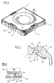
- a holding plate 17 is placed on the top 15 of the balance housing 3 and by means not shown with the balance housing 3 firmly connected. At the edges of the holding plate 17 are vertically protruding ribs or tabs 51 protruding from the latter.
- the pairs of tabs 51 lie at a mutual distance a to form a slot 52.
- a groove, notch or step 53 is embedded on the outside of at least one tab of the pair of tabs 51.
- a groove or a groove-shaped recess 55 which, when the draft shield 9 is attached, can accommodate the pairs of tabs 51 attached to the holding plate 17.
- webs 57 bridging the groove walls are attached in the grooves 55 and are intended to engage between the pairs of tabs 51.
- the webs 57 are dimensioned such that they come to lie in the slots 52 between the pairs of tabs 51 with little play.
- a detent spring 59 is fastened to the side of the web 57 mounted there in the recess 55, the front end 61 of which protrudes into the groove 53.
- the front section of the spring is arranged inclined to the vertical, so that when the draft shield 9 is placed on the holding plate 17 it is pushed back by the tab 51 entering the recess 55 until the front end 61 of the spring 59 snaps into the groove 53.
- the snapping takes place approximately at the moment when the draft shield 9 is placed on the holding plate 17 or the surface 15 of the scale housing 3.
- the windbreak 9 can no longer spontaneously lift off at the front. Tilting of the windshield 9 when opening the cover 13 is consequently no longer possible.
- the draft shield 9 on the back must be raised slightly such that the spring 59 is guided out of the groove 3 by pivoting the draft shield 9. Then the draft shield 9 can be lifted off the housing 3.
- a pin 263 which is embedded in the groove 255 and bridges the two groove walls, is inserted .
- the slit-shaped tabs 251 replace the tab pairs 51 in FIG. 6 and are fastened on the holding plate 217.
- the draft shield 209 is placed on the scale housing 203 as follows.
- the draft shield 209 is placed on the tabs 251 from above and then slides down the sloping path of the slots 265. As soon as the draft shield 209 rests on the scale housing 203, it can no longer spontaneously lift off on the operator side.
- the windshield is pushed forward with a slight lift until the connection between pin 263 and slot 265 is released.
Landscapes
- Physics & Mathematics (AREA)
- General Physics & Mathematics (AREA)
- Closing And Opening Devices For Wings, And Checks For Wings (AREA)
- Hinges (AREA)
- Cookers (AREA)
- Paper (AREA)
Applications Claiming Priority (2)
| Application Number | Priority Date | Filing Date | Title |
|---|---|---|---|
| CH402/93 | 1993-02-09 | ||
| CH402/93A CH685173A5 (de) | 1993-02-09 | 1993-02-09 | Oberschalige Präzisionswaage mit einem Windschutz. |
Publications (2)
| Publication Number | Publication Date |
|---|---|
| EP0610549A1 true EP0610549A1 (fr) | 1994-08-17 |
| EP0610549B1 EP0610549B1 (fr) | 1997-07-23 |
Family
ID=4186210
Family Applications (1)
| Application Number | Title | Priority Date | Filing Date |
|---|---|---|---|
| EP93116492A Expired - Lifetime EP0610549B1 (fr) | 1993-02-09 | 1993-10-12 | Balance de précision à plateaux supérieurs avec une protection contre le vent |
Country Status (5)
| Country | Link |
|---|---|
| US (1) | US5583322A (fr) |
| EP (1) | EP0610549B1 (fr) |
| JP (1) | JP2500940Y2 (fr) |
| CH (1) | CH685173A5 (fr) |
| DE (2) | DE9313902U1 (fr) |
Families Citing this family (17)
| Publication number | Priority date | Publication date | Assignee | Title |
|---|---|---|---|---|
| JP3501857B2 (ja) | 1994-11-07 | 2004-03-02 | 株式会社エー・アンド・デイ | 秤用風防装置 |
| IT240940Y1 (it) * | 1996-10-10 | 2001-04-11 | Table Top Engineering & Design | Scaldavivande con coperchio ad apertura controllata |
| DE19849399A1 (de) * | 1998-10-27 | 2000-05-04 | Mettler Toledo Gmbh | Windschutz für eine Waage und Waage mit einem Windschutz |
| JP3449261B2 (ja) | 1998-11-30 | 2003-09-22 | 株式会社島津製作所 | 天 秤 |
| US6686545B2 (en) * | 2000-10-04 | 2004-02-03 | Mettler-Toledo Gmbh | Balance with a weighing compartment |
| US6833515B1 (en) * | 2001-12-19 | 2004-12-21 | Joshua D. Kesselman | Handheld electronic scale |
| EP1367372B1 (fr) * | 2002-05-29 | 2005-11-23 | Mettler-Toledo GmbH | Dispositif de protection contre le vent pour une balance et balance avec un dispositif de protection contre le vent |
| DE10330788A1 (de) * | 2003-07-07 | 2005-02-10 | Mettler-Toledo Gmbh | Waage mit Windschutzelement |
| US7732720B2 (en) * | 2005-02-18 | 2010-06-08 | Ohaus Corporation Usa | Draft protection device for a balance and having a friction reduction device |
| US7411137B2 (en) * | 2005-10-25 | 2008-08-12 | Formax, Inc. | Automatic sealing arrangement for weigh scale for food processing apparatus |
| JP5062880B2 (ja) * | 2007-03-05 | 2012-10-31 | 株式会社エー・アンド・デイ | 秤量装置用着脱型風防 |
| JP2009014429A (ja) * | 2007-07-03 | 2009-01-22 | Seiko Epson Corp | 重量測定装置、液滴吐出装置及び重量測定方法 |
| PL2088406T3 (pl) * | 2008-02-06 | 2012-08-31 | Mettler Toledo Gmbh | Waga z osłoną przed wiatrem |
| DE102010050225A1 (de) | 2010-11-04 | 2012-05-10 | Mettler-Toledo Ag | Windschutzvorrichtung für eine Waage |
| PT2825145T (pt) * | 2012-03-16 | 2019-06-28 | Ricon Corp | Disposição de elevação de cadeira de rodas com sistema de deteção de carga |
| CN103674215B (zh) * | 2012-08-30 | 2018-03-30 | 梅特勒-托利多有限公司 | 用于天平的防风罩 |
| DE102013112998B4 (de) * | 2013-11-25 | 2021-10-21 | Sartorius Lab Instruments Gmbh & Co. Kg | Deckel eines Windschutzes einer Präzisionswaage sowie Windschutz für eine Präzisionswaage |
Citations (6)
| Publication number | Priority date | Publication date | Assignee | Title |
|---|---|---|---|---|
| US3250585A (en) * | 1964-06-19 | 1966-05-10 | Dominion Electrohome Ind Ltd | Combination torsion bar-hinge pin for an enclosure having a lid |
| US3498207A (en) * | 1968-03-28 | 1970-03-03 | Robertson Co H H | Torsion bar operated venting unit |
| CH578106A5 (en) * | 1975-02-05 | 1976-07-30 | Zug Metallwarenfabrik | Door hinge for domestic oven - L-shaped hinge rod each end plugs into tube both sides of oven frame |
| EP0046821A1 (fr) * | 1980-08-27 | 1982-03-10 | Hans Vollmer | Armature pour lucarne |
| EP0282400A2 (fr) * | 1987-03-09 | 1988-09-14 | Louis Mathian | Dispositif de pesée grand public |
| DE8907396U1 (de) * | 1988-08-05 | 1989-08-03 | Mettler Instrumente AG, Greifensee | Windschutz für Präzisionswaagen mit freiliegender Waagschale |
Family Cites Families (7)
| Publication number | Priority date | Publication date | Assignee | Title |
|---|---|---|---|---|
| US3810275A (en) * | 1972-06-26 | 1974-05-14 | Gsw Appliances Ltd | Hinge structure |
| US3941300A (en) * | 1974-07-19 | 1976-03-02 | Pamark, Inc. | Folded plastic container with snap lid |
| US4148106A (en) * | 1977-12-27 | 1979-04-10 | Gallien John W | Furniture fastener system |
| NL7901121A (nl) * | 1979-02-13 | 1980-08-15 | Philips Nv | Wrijvingsscharnierinrichting. |
| JPS62101715A (ja) * | 1985-10-29 | 1987-05-12 | Kajima Corp | スライム処理装置 |
| US4862978A (en) * | 1988-04-29 | 1989-09-05 | Borchard John S | Combination dust cover and air screen |
| JP2873608B2 (ja) * | 1990-07-07 | 1999-03-24 | 日本発条株式会社 | 開閉装置 |
-
1993
- 1993-02-09 CH CH402/93A patent/CH685173A5/de unknown
- 1993-09-10 US US08/119,990 patent/US5583322A/en not_active Expired - Lifetime
- 1993-09-14 DE DE9313902U patent/DE9313902U1/de not_active Expired - Lifetime
- 1993-10-12 EP EP93116492A patent/EP0610549B1/fr not_active Expired - Lifetime
- 1993-10-12 DE DE59306973T patent/DE59306973D1/de not_active Expired - Lifetime
- 1993-11-12 JP JP1993060894U patent/JP2500940Y2/ja not_active Expired - Lifetime
Patent Citations (6)
| Publication number | Priority date | Publication date | Assignee | Title |
|---|---|---|---|---|
| US3250585A (en) * | 1964-06-19 | 1966-05-10 | Dominion Electrohome Ind Ltd | Combination torsion bar-hinge pin for an enclosure having a lid |
| US3498207A (en) * | 1968-03-28 | 1970-03-03 | Robertson Co H H | Torsion bar operated venting unit |
| CH578106A5 (en) * | 1975-02-05 | 1976-07-30 | Zug Metallwarenfabrik | Door hinge for domestic oven - L-shaped hinge rod each end plugs into tube both sides of oven frame |
| EP0046821A1 (fr) * | 1980-08-27 | 1982-03-10 | Hans Vollmer | Armature pour lucarne |
| EP0282400A2 (fr) * | 1987-03-09 | 1988-09-14 | Louis Mathian | Dispositif de pesée grand public |
| DE8907396U1 (de) * | 1988-08-05 | 1989-08-03 | Mettler Instrumente AG, Greifensee | Windschutz für Präzisionswaagen mit freiliegender Waagschale |
Also Published As
| Publication number | Publication date |
|---|---|
| EP0610549B1 (fr) | 1997-07-23 |
| DE59306973D1 (de) | 1997-09-04 |
| JPH0662330U (ja) | 1994-09-02 |
| DE9313902U1 (de) | 1993-11-18 |
| CH685173A5 (de) | 1995-04-13 |
| JP2500940Y2 (ja) | 1996-06-12 |
| US5583322A (en) | 1996-12-10 |
Similar Documents
| Publication | Publication Date | Title |
|---|---|---|
| EP0610549B1 (fr) | Balance de précision à plateaux supérieurs avec une protection contre le vent | |
| DE69922901T2 (de) | Schnappscharnier zum Tragen von Türpaneelen | |
| DE2547319C3 (de) | Verriegelung für Fenster oder Türen | |
| DE69020604T2 (de) | Verborgene Vorrichtung zur Wandmontage eines Wandmöbelelementes. | |
| EP0626497A1 (fr) | Butée de porte | |
| DE19949185A1 (de) | Türscharnier | |
| EP0890696A2 (fr) | Armoire de commande pour l'électronique et l'électrotechnique | |
| EP3111801A1 (fr) | Dispositif porteur pour meuble | |
| DE19924056A1 (de) | Halterung für ein justierbares Gehäuse | |
| DE4128486A1 (de) | Verschlussvorrichtung fuer fluegel | |
| DE3004854C2 (de) | Feststellvorrichtung für Flügel von Fenstern, Türen o.dgl. in wenigstens einer Spaltlüftungsstellung | |
| DE1759642C3 (de) | Mehrfach verstellbares Scharnier | |
| EP2157266B1 (fr) | Charnière pour un article de mobilier doté d'une porte | |
| DE60008211T2 (de) | Verschlussvorrichtung einer Frontplatte für einen Wärmetauscher eines Wäschetrommeltrockners mit Kondensateinrichtung | |
| DE3203321C2 (fr) | ||
| DE3125966C2 (fr) | ||
| DE7902216U1 (de) | Geräteschrank | |
| DE4242583A1 (de) | Vorrichtung für Dunstabzugshauben zum Ein- oder Zwischenbau in Hängeschrankelemente | |
| DE29615631U1 (de) | Sicherungseinrichtung | |
| CH681485A5 (fr) | ||
| DE2826945B1 (de) | Ecklager fuer Drehkippfenster oder -tueren | |
| DE2442473C2 (de) | Zargenunterband für Holz- oder Kunststoffzargen für rechts- oder linksanschlagbare Normtüren | |
| DE69002154T2 (de) | Mehrzweckregal. | |
| DE19737425A1 (de) | Schaltschrank mit einem Schwenkrahmen | |
| EP0340455B1 (fr) | Pivot pour la connexion de deux battants d'une fenêtre, d'une porte ou similaire |
Legal Events
| Date | Code | Title | Description |
|---|---|---|---|
| PUAI | Public reference made under article 153(3) epc to a published international application that has entered the european phase |
Free format text: ORIGINAL CODE: 0009012 |
|
| 17P | Request for examination filed |
Effective date: 19940221 |
|
| AK | Designated contracting states |
Kind code of ref document: A1 Designated state(s): DE FR GB |
|
| 17Q | First examination report despatched |
Effective date: 19960126 |
|
| GRAG | Despatch of communication of intention to grant |
Free format text: ORIGINAL CODE: EPIDOS AGRA |
|
| GRAG | Despatch of communication of intention to grant |
Free format text: ORIGINAL CODE: EPIDOS AGRA |
|
| GRAH | Despatch of communication of intention to grant a patent |
Free format text: ORIGINAL CODE: EPIDOS IGRA |
|
| GRAH | Despatch of communication of intention to grant a patent |
Free format text: ORIGINAL CODE: EPIDOS IGRA |
|
| GRAA | (expected) grant |
Free format text: ORIGINAL CODE: 0009210 |
|
| RAP1 | Party data changed (applicant data changed or rights of an application transferred) |
Owner name: METTLER-TOLEDO GMBH |
|
| AK | Designated contracting states |
Kind code of ref document: B1 Designated state(s): DE FR GB |
|
| REF | Corresponds to: |
Ref document number: 59306973 Country of ref document: DE Date of ref document: 19970904 |
|
| GBT | Gb: translation of ep patent filed (gb section 77(6)(a)/1977) |
Effective date: 19970828 |
|
| ET | Fr: translation filed | ||
| PLBE | No opposition filed within time limit |
Free format text: ORIGINAL CODE: 0009261 |
|
| STAA | Information on the status of an ep patent application or granted ep patent |
Free format text: STATUS: NO OPPOSITION FILED WITHIN TIME LIMIT |
|
| 26N | No opposition filed | ||
| PGFP | Annual fee paid to national office [announced via postgrant information from national office to epo] |
Ref country code: FR Payment date: 19990920 Year of fee payment: 7 |
|
| PG25 | Lapsed in a contracting state [announced via postgrant information from national office to epo] |
Ref country code: FR Free format text: LAPSE BECAUSE OF NON-PAYMENT OF DUE FEES Effective date: 20010629 |
|
| REG | Reference to a national code |
Ref country code: FR Ref legal event code: ST |
|
| REG | Reference to a national code |
Ref country code: GB Ref legal event code: IF02 |
|
| PGFP | Annual fee paid to national office [announced via postgrant information from national office to epo] |
Ref country code: DE Payment date: 20101022 Year of fee payment: 18 |
|
| PGFP | Annual fee paid to national office [announced via postgrant information from national office to epo] |
Ref country code: GB Payment date: 20110930 Year of fee payment: 19 |
|
| GBPC | Gb: european patent ceased through non-payment of renewal fee |
Effective date: 20121012 |
|
| PG25 | Lapsed in a contracting state [announced via postgrant information from national office to epo] |
Ref country code: GB Free format text: LAPSE BECAUSE OF NON-PAYMENT OF DUE FEES Effective date: 20121012 Ref country code: DE Free format text: LAPSE BECAUSE OF NON-PAYMENT OF DUE FEES Effective date: 20130501 |
|
| REG | Reference to a national code |
Ref country code: DE Ref legal event code: R119 Ref document number: 59306973 Country of ref document: DE Effective date: 20130501 |