EP0610572A1 - Ensemble de pompage de liquide de lavage d'un réservoir à un gicleur de véhicule automobile - Google Patents
Ensemble de pompage de liquide de lavage d'un réservoir à un gicleur de véhicule automobile Download PDFInfo
- Publication number
- EP0610572A1 EP0610572A1 EP93119909A EP93119909A EP0610572A1 EP 0610572 A1 EP0610572 A1 EP 0610572A1 EP 93119909 A EP93119909 A EP 93119909A EP 93119909 A EP93119909 A EP 93119909A EP 0610572 A1 EP0610572 A1 EP 0610572A1
- Authority
- EP
- European Patent Office
- Prior art keywords
- pump
- conveying
- unit according
- washing liquid
- partition
- Prior art date
- Legal status (The legal status is an assumption and is not a legal conclusion. Google has not performed a legal analysis and makes no representation as to the accuracy of the status listed.)
- Granted
Links
- 238000005406 washing Methods 0.000 title claims abstract description 25
- 239000007788 liquid Substances 0.000 title claims abstract description 14
- 238000005086 pumping Methods 0.000 title abstract 5
- 239000007921 spray Substances 0.000 title description 2
- 238000005192 partition Methods 0.000 claims description 16
- 238000004140 cleaning Methods 0.000 abstract description 3
- 238000010276 construction Methods 0.000 description 1
- 238000011161 development Methods 0.000 description 1
- 230000018109 developmental process Effects 0.000 description 1
- 238000004519 manufacturing process Methods 0.000 description 1
Images


Classifications
-
- F—MECHANICAL ENGINEERING; LIGHTING; HEATING; WEAPONS; BLASTING
- F04—POSITIVE - DISPLACEMENT MACHINES FOR LIQUIDS; PUMPS FOR LIQUIDS OR ELASTIC FLUIDS
- F04D—NON-POSITIVE-DISPLACEMENT PUMPS
- F04D29/00—Details, component parts, or accessories
- F04D29/40—Casings; Connections of working fluid
- F04D29/42—Casings; Connections of working fluid for radial or helico-centrifugal pumps
- F04D29/44—Fluid-guiding means, e.g. diffusers
- F04D29/445—Fluid-guiding means, e.g. diffusers especially adapted for liquid pumps
- F04D29/448—Fluid-guiding means, e.g. diffusers especially adapted for liquid pumps bladed diffusers
-
- F—MECHANICAL ENGINEERING; LIGHTING; HEATING; WEAPONS; BLASTING
- F04—POSITIVE - DISPLACEMENT MACHINES FOR LIQUIDS; PUMPS FOR LIQUIDS OR ELASTIC FLUIDS
- F04D—NON-POSITIVE-DISPLACEMENT PUMPS
- F04D1/00—Radial-flow pumps, e.g. centrifugal pumps; Helico-centrifugal pumps
- F04D1/06—Multi-stage pumps
- F04D1/063—Multi-stage pumps of the vertically split casing type
-
- F—MECHANICAL ENGINEERING; LIGHTING; HEATING; WEAPONS; BLASTING
- F04—POSITIVE - DISPLACEMENT MACHINES FOR LIQUIDS; PUMPS FOR LIQUIDS OR ELASTIC FLUIDS
- F04D—NON-POSITIVE-DISPLACEMENT PUMPS
- F04D29/00—Details, component parts, or accessories
- F04D29/18—Rotors
- F04D29/185—Rotors consisting of a plurality of wheels
Definitions
- the invention relates to a conveyor unit according to the type of the main claim.
- a delivery unit is already known in which the pump has only one delivery pump designed as a flow pump. Taking into account a construction and manufacturing effort that is still justifiable for cost reasons, the known flow pump reaches a maximum delivery pressure of approximately 2.5 bar, which in many cases leads to proper cleaning of the pane only after repeated operation of the washing system. However, an undesirably large amount of the washing liquid which is only available to a limited extent is consumed.
- the delivery unit according to the invention with the characterizing features of the main claim has the advantage that its 2-stage pump reaches a delivery pressure of about 5 bar, so that intensive cleaning of the disc is achieved quickly and with a small amount of washing liquid.
- FIG. 1 shows an unscaled basic illustration of a washing system with a conveyor unit according to the invention
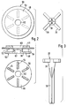
- FIG. 2 shows a multi-functional component belonging to the conveyor unit in a view, in longitudinal section and in section along the section line
- FIG. 3 shows a conveyor member belonging to the conveyor pump in a view and plan view, of the pre-feed pump in section and in different views
- FIG. 5 shows the feed elements of the feed pump and the pre-feed pump, the feed element of the pre-feed pump being plugged onto an extension of the feed element of the feed pump.
- a washing system shown in FIG. 1 has a storage tank 10 for washing liquid, into which a suction line or a suction pipe 12 of a delivery unit 14 is immersed.
- the conveyor unit has an electric drive motor 16, which is housed in a unit housing 18.
- the armature shaft 20 of the drive motor 16 penetrates the unit housing 18.
- the free end of the armature shaft 20 projects into a pump chamber 22 which belongs to a feed pump 24.
- a pump housing 26 is attached, on which the suction line 12 is molded as a suction nozzle.
- a conveying member 28 is connected in a rotationally fixed manner, which in the pump chamber 22 when the electric motor 16 is running circulates. As can be seen in particular from FIG.
- the conveying member 28 is designed as an impeller and it has a central extension 30 which extends into the suction nozzle 12.
- the approach 30 ensures good suction behavior of the pump.
- the conveying member 28 has a central, conically shaped area 31 which tapers towards the shoulder 30 and whose largest diameter is in the area of the vanes 29.
- a second conveyor member 32 designed as an impeller is plugged onto the extension 30 of the conveyor member 28. This can be seen particularly clearly from FIG. 5.
- the delivery member 32 belongs to a pre-delivery pump 34, the backing pump chamber 36 of which is located within the housing 26.
- the unit 14 also has a pressure port 38 which is conductively connected to the pump chamber 22 of the feed pump 24.
- a pressure line 40 is connected to the pressure nozzle 38, which leads from the delivery unit 14 to a washing nozzle 42, the spray jet of which is directed in the exemplary embodiment onto the cover plate 44 of a headlight 46, which belongs to a motor vehicle (not shown). Deviating from the exemplary embodiment described, it is also conceivable, however, to direct one or more such washing nozzles onto other windows, for example the front window or the rear window of a motor vehicle.
- the pump chamber 22 and the fore-pump chamber 36 are separated from one another by a partition 48.
- the partition 48 is part of a one-piece multifunctional element 50, the structure of which can be seen particularly in FIG. 2.
- the partition 48 belonging to the multifunctional element 50 is essentially disc-shaped and closes the pump chamber 22 of the feed pump 24 in the axial direction, on the side facing away from the drive motor 16.
- the diameter of the flow guide element 56 is smaller than the substantially circular diameter of the backing pump chamber 36
- Guide ribs 54 keep the flow guide element 56 at a distance from the partition wall 48.
- the end face 58 of the flow guide element 56 facing away from the partition wall delimits the backing pump chamber 36 on its side facing the drive motor 16.
- the forepump chamber 36 is delimited by the housing 26 on the side facing away from the drive motor 16.
- Both the partition 48 and the flow guide element 56 have central bores 60 and 62, through which the extension 30 of the conveying member 28 extends.
- An overflow channel 64 thus results between the flow guide element 56 and the partition 48, which extends further in the area of the central bore 60 of the partition 48 and opens into the pump chamber 22 of the feed pump 24.
- the extension 30 of the delivery member 28 has a cross-shaped cross-section, onto which the delivery member 32 of the pre-delivery pump 34 is attached.
- the conveying member 32 has a central, cross-shaped opening 66, so that proper rotational driving is ensured.
- the washing liquid is guided by the guide ribs 54 so that, following the arrows 76, it reaches the pump chamber 22 of the feed pump 24 via the bore 60. From there, the washing liquid is pressed into the pressure port 38 and fed to the washing nozzle 42 via the pressure line.
- the cone-shaped area 31 of the conveying member 28 in connection with the opening 62 of the multi-functional elements 50 seals between the 1st and 2nd stage of the pump and thus prevents an internal leakage flow (Fig . 1).
Landscapes
- Engineering & Computer Science (AREA)
- Mechanical Engineering (AREA)
- General Engineering & Computer Science (AREA)
- Structures Of Non-Positive Displacement Pumps (AREA)
- Cleaning By Liquid Or Steam (AREA)
Applications Claiming Priority (2)
| Application Number | Priority Date | Filing Date | Title |
|---|---|---|---|
| DE4300407A DE4300407A1 (de) | 1993-01-09 | 1993-01-09 | Aggregat zum Fördern von Waschflüssigkeit aus einem Vorratstank zu einer auf eine Scheibe eines Kraftfahrzeuges gerichteten Waschdüse |
| DE4300407 | 1993-01-09 |
Publications (2)
| Publication Number | Publication Date |
|---|---|
| EP0610572A1 true EP0610572A1 (fr) | 1994-08-17 |
| EP0610572B1 EP0610572B1 (fr) | 1997-03-12 |
Family
ID=6477916
Family Applications (1)
| Application Number | Title | Priority Date | Filing Date |
|---|---|---|---|
| EP93119909A Expired - Lifetime EP0610572B1 (fr) | 1993-01-09 | 1993-12-10 | Ensemble de pompage de liquide de lavage d'un réservoir à un gicleur de véhicule automobile |
Country Status (4)
| Country | Link |
|---|---|
| EP (1) | EP0610572B1 (fr) |
| JP (1) | JPH06227370A (fr) |
| DE (2) | DE4300407A1 (fr) |
| ES (1) | ES2099358T3 (fr) |
Cited By (5)
| Publication number | Priority date | Publication date | Assignee | Title |
|---|---|---|---|---|
| CN114688092A (zh) * | 2020-12-31 | 2022-07-01 | 宁波方太厨具有限公司 | 一种水泵的蜗壳结构及双泵系统、清洗机 |
| CN114688040A (zh) * | 2020-12-31 | 2022-07-01 | 宁波方太厨具有限公司 | 一种双泵系统及应用有双泵系统的清洗机 |
| CN114688087A (zh) * | 2020-12-31 | 2022-07-01 | 宁波方太厨具有限公司 | 一种水泵的蜗壳结构及双泵系统、清洗机 |
| CN114688041A (zh) * | 2020-12-31 | 2022-07-01 | 宁波方太厨具有限公司 | 一种水流系统及应用有该水流系统的清洗机 |
| CN114688088A (zh) * | 2020-12-31 | 2022-07-01 | 宁波方太厨具有限公司 | 一种水泵的蜗壳结构及双泵系统、清洗机 |
Families Citing this family (2)
| Publication number | Priority date | Publication date | Assignee | Title |
|---|---|---|---|---|
| EP1939454A1 (fr) * | 2006-12-29 | 2008-07-02 | Grundfos Management A/S | Unité de pompage |
| KR100973709B1 (ko) * | 2008-08-21 | 2010-08-04 | 콘티넨탈 오토모티브 일렉트로닉스 유한회사 | 자동차의 워셔액 펌프 |
Citations (4)
| Publication number | Priority date | Publication date | Assignee | Title |
|---|---|---|---|---|
| DE2034489A1 (de) * | 1970-07-11 | 1972-01-13 | Allweiler Ag | Zweistufige Kreiselpumpe |
| FR2322273A1 (fr) * | 1975-08-30 | 1977-03-25 | Rau Swf Autozubehoer | Pompe a carburant, notamment pour vehicules automobiles |
| DE2735508A1 (de) * | 1977-08-06 | 1979-02-15 | Bosch Gmbh Robert | Waschvorrichtung fuer abdeckscheiben von kraftfahrzeugleuchten |
| FR2462594A1 (fr) * | 1979-07-30 | 1981-02-13 | Transpar Iberica Sa | Pompe electrique pour lave-glace de vehicules automobiles |
-
1993
- 1993-01-09 DE DE4300407A patent/DE4300407A1/de not_active Withdrawn
- 1993-12-10 EP EP93119909A patent/EP0610572B1/fr not_active Expired - Lifetime
- 1993-12-10 ES ES93119909T patent/ES2099358T3/es not_active Expired - Lifetime
- 1993-12-10 DE DE59305771T patent/DE59305771D1/de not_active Expired - Fee Related
- 1993-12-28 JP JP5337066A patent/JPH06227370A/ja active Pending
Patent Citations (4)
| Publication number | Priority date | Publication date | Assignee | Title |
|---|---|---|---|---|
| DE2034489A1 (de) * | 1970-07-11 | 1972-01-13 | Allweiler Ag | Zweistufige Kreiselpumpe |
| FR2322273A1 (fr) * | 1975-08-30 | 1977-03-25 | Rau Swf Autozubehoer | Pompe a carburant, notamment pour vehicules automobiles |
| DE2735508A1 (de) * | 1977-08-06 | 1979-02-15 | Bosch Gmbh Robert | Waschvorrichtung fuer abdeckscheiben von kraftfahrzeugleuchten |
| FR2462594A1 (fr) * | 1979-07-30 | 1981-02-13 | Transpar Iberica Sa | Pompe electrique pour lave-glace de vehicules automobiles |
Cited By (5)
| Publication number | Priority date | Publication date | Assignee | Title |
|---|---|---|---|---|
| CN114688092A (zh) * | 2020-12-31 | 2022-07-01 | 宁波方太厨具有限公司 | 一种水泵的蜗壳结构及双泵系统、清洗机 |
| CN114688040A (zh) * | 2020-12-31 | 2022-07-01 | 宁波方太厨具有限公司 | 一种双泵系统及应用有双泵系统的清洗机 |
| CN114688087A (zh) * | 2020-12-31 | 2022-07-01 | 宁波方太厨具有限公司 | 一种水泵的蜗壳结构及双泵系统、清洗机 |
| CN114688041A (zh) * | 2020-12-31 | 2022-07-01 | 宁波方太厨具有限公司 | 一种水流系统及应用有该水流系统的清洗机 |
| CN114688088A (zh) * | 2020-12-31 | 2022-07-01 | 宁波方太厨具有限公司 | 一种水泵的蜗壳结构及双泵系统、清洗机 |
Also Published As
| Publication number | Publication date |
|---|---|
| EP0610572B1 (fr) | 1997-03-12 |
| DE4300407A1 (de) | 1994-07-14 |
| ES2099358T3 (es) | 1997-05-16 |
| DE59305771D1 (de) | 1997-04-17 |
| JPH06227370A (ja) | 1994-08-16 |
Similar Documents
| Publication | Publication Date | Title |
|---|---|---|
| EP0487538B1 (fr) | Dispositif de chauffage de l'interieur de vehicules a moteur | |
| EP3779201A1 (fr) | Élément de raclage pour bords d'attaque de roue à aubes pour des pompes à eau | |
| DE4304149C1 (de) | Selbstansaugendes Motorpumpenaggregat | |
| DE69015918T2 (de) | Windschutzscheiben-Waschpumpe für ein Fahrzeug. | |
| EP0610572B1 (fr) | Ensemble de pompage de liquide de lavage d'un réservoir à un gicleur de véhicule automobile | |
| DE2249510A1 (de) | Fluessigkeitspumpenaggregat, insbesondere fuer den einsatz in geschirrspuelmaschinen | |
| DE3023897C2 (de) | Scheibenwaschanlage eines Fahrzeuges | |
| DE69013788T2 (de) | Windschutzscheiben-Waschanlagenpumpe für Fahrzeuge. | |
| DE10024741B4 (de) | Seitenkanalpumpe | |
| EP0013942B1 (fr) | Pompe centrifuge pour liquides contenant des matières solides | |
| DE4446106C2 (de) | Brennstoffpumpe für Kraftfahrzeuge | |
| EP1085995A1 (fr) | Dispositif permettant de transporter le carburant d'un reservoir jusqu'au moteur a combustion interne d'un vehicule automobile | |
| DE29702253U1 (de) | Pumpe für Waschmaschinen, Wäschetrockner, Geschirrspülmaschinen u.dgl. | |
| DE3900263A1 (de) | Aggregat zum foerdern von kraftstoff aus einem vorratstank zur brennkraftmaschine eines kraftfahrzeuges | |
| DE102008034721A1 (de) | Pumpeneinheit sowie Versorgungseinheit zur Verwendung bei einer Scheibenwaschanlage für Fahrzeuge sowie Scheibenwaschanlage | |
| EP1913262A1 (fr) | Corps de pompe, pompe et appareil menager a circulation d'eau | |
| DE4305023A1 (fr) | ||
| EP0601220B1 (fr) | Système de pompe hydraulique, en particulier pompe de vidage de liquides | |
| DE2522165A1 (de) | Kreiselpumpe | |
| DE10019819A1 (de) | Pumpe, insbesondere Umwälzpumpe für Haushaltsmaschinen wie Geschirrspülmaschinen | |
| DE10227281A1 (de) | Vorrichtung zum Fördern von Kraftstoff aus einem Vorratsbehälter zur Brennkraftmaschine eines Kraftfahrzeugs | |
| DE10019820C2 (de) | Pumpe, insbesondere Umwälzpumpe für Haushaltsmaschinen wie Geschirrspülmaschinen | |
| EP3762607B1 (fr) | Dispositif de pompage pour un boîtier de système d'un véhicule | |
| EP0580823B1 (fr) | Installation de lavage particulierement destinee aux vitres d'un vehicule automobile | |
| DE69503836T2 (de) | Vorlaufrad einer Pumpe für Windschutzscheibenwascher bei Kraftfahrzeugen |
Legal Events
| Date | Code | Title | Description |
|---|---|---|---|
| PUAI | Public reference made under article 153(3) epc to a published international application that has entered the european phase |
Free format text: ORIGINAL CODE: 0009012 |
|
| AK | Designated contracting states |
Kind code of ref document: A1 Designated state(s): CH DE ES FR IT LI |
|
| 17P | Request for examination filed |
Effective date: 19950217 |
|
| 17Q | First examination report despatched |
Effective date: 19960205 |
|
| GRAG | Despatch of communication of intention to grant |
Free format text: ORIGINAL CODE: EPIDOS AGRA |
|
| GRAH | Despatch of communication of intention to grant a patent |
Free format text: ORIGINAL CODE: EPIDOS IGRA |
|
| GRAH | Despatch of communication of intention to grant a patent |
Free format text: ORIGINAL CODE: EPIDOS IGRA |
|
| GRAA | (expected) grant |
Free format text: ORIGINAL CODE: 0009210 |
|
| AK | Designated contracting states |
Kind code of ref document: B1 Designated state(s): CH DE ES FR IT LI |
|
| REG | Reference to a national code |
Ref country code: CH Ref legal event code: NV Representative=s name: SCINTILLA AG, DIREKTION Ref country code: CH Ref legal event code: EP |
|
| ET | Fr: translation filed | ||
| REF | Corresponds to: |
Ref document number: 59305771 Country of ref document: DE Date of ref document: 19970417 |
|
| REG | Reference to a national code |
Ref country code: ES Ref legal event code: FG2A Ref document number: 2099358 Country of ref document: ES Kind code of ref document: T3 |
|
| ITF | It: translation for a ep patent filed | ||
| PLBE | No opposition filed within time limit |
Free format text: ORIGINAL CODE: 0009261 |
|
| STAA | Information on the status of an ep patent application or granted ep patent |
Free format text: STATUS: NO OPPOSITION FILED WITHIN TIME LIMIT |
|
| 26N | No opposition filed | ||
| PGFP | Annual fee paid to national office [announced via postgrant information from national office to epo] |
Ref country code: FR Payment date: 19981218 Year of fee payment: 6 |
|
| PGFP | Annual fee paid to national office [announced via postgrant information from national office to epo] |
Ref country code: CH Payment date: 19981222 Year of fee payment: 6 Ref country code: ES Payment date: 19981222 Year of fee payment: 6 |
|
| PGFP | Annual fee paid to national office [announced via postgrant information from national office to epo] |
Ref country code: DE Payment date: 19990223 Year of fee payment: 6 |
|
| PG25 | Lapsed in a contracting state [announced via postgrant information from national office to epo] |
Ref country code: LI Free format text: LAPSE BECAUSE OF NON-PAYMENT OF DUE FEES Effective date: 19991231 Ref country code: CH Free format text: LAPSE BECAUSE OF NON-PAYMENT OF DUE FEES Effective date: 19991231 |
|
| PG25 | Lapsed in a contracting state [announced via postgrant information from national office to epo] |
Ref country code: FR Free format text: LAPSE BECAUSE OF NON-PAYMENT OF DUE FEES Effective date: 20000831 |
|
| PG25 | Lapsed in a contracting state [announced via postgrant information from national office to epo] |
Ref country code: DE Free format text: LAPSE BECAUSE OF NON-PAYMENT OF DUE FEES Effective date: 20001003 |
|
| REG | Reference to a national code |
Ref country code: FR Ref legal event code: ST |
|
| PG25 | Lapsed in a contracting state [announced via postgrant information from national office to epo] |
Ref country code: ES Free format text: LAPSE BECAUSE OF NON-PAYMENT OF DUE FEES Effective date: 20001211 |
|
| REG | Reference to a national code |
Ref country code: ES Ref legal event code: FD2A Effective date: 20010113 |
|
| PG25 | Lapsed in a contracting state [announced via postgrant information from national office to epo] |
Ref country code: IT Free format text: LAPSE BECAUSE OF NON-PAYMENT OF DUE FEES Effective date: 20051210 |