EP0610620B1 - Une méthode pour gainage d'une conduite latérale - Google Patents
Une méthode pour gainage d'une conduite latérale Download PDFInfo
- Publication number
- EP0610620B1 EP0610620B1 EP93308428A EP93308428A EP0610620B1 EP 0610620 B1 EP0610620 B1 EP 0610620B1 EP 93308428 A EP93308428 A EP 93308428A EP 93308428 A EP93308428 A EP 93308428A EP 0610620 B1 EP0610620 B1 EP 0610620B1
- Authority
- EP
- European Patent Office
- Prior art keywords
- liner bag
- branch pipe
- main pipe
- liner
- bag
- Prior art date
- Legal status (The legal status is an assumption and is not a legal conclusion. Google has not performed a legal analysis and makes no representation as to the accuracy of the status listed.)
- Expired - Lifetime
Links
Images


Classifications
-
- B—PERFORMING OPERATIONS; TRANSPORTING
- B29—WORKING OF PLASTICS; WORKING OF SUBSTANCES IN A PLASTIC STATE IN GENERAL
- B29C—SHAPING OR JOINING OF PLASTICS; SHAPING OF MATERIAL IN A PLASTIC STATE, NOT OTHERWISE PROVIDED FOR; AFTER-TREATMENT OF THE SHAPED PRODUCTS, e.g. REPAIRING
- B29C63/00—Lining or sheathing, i.e. applying preformed layers or sheathings of plastics; Apparatus therefor
- B29C63/26—Lining or sheathing of internal surfaces
- B29C63/30—Lining or sheathing of internal surfaces using sheet or web-like material
-
- F—MECHANICAL ENGINEERING; LIGHTING; HEATING; WEAPONS; BLASTING
- F16—ENGINEERING ELEMENTS AND UNITS; GENERAL MEASURES FOR PRODUCING AND MAINTAINING EFFECTIVE FUNCTIONING OF MACHINES OR INSTALLATIONS; THERMAL INSULATION IN GENERAL
- F16L—PIPES; JOINTS OR FITTINGS FOR PIPES; SUPPORTS FOR PIPES, CABLES OR PROTECTIVE TUBING; MEANS FOR THERMAL INSULATION IN GENERAL
- F16L55/00—Devices or appurtenances for use in, or in connection with, pipes or pipe systems
- F16L55/16—Devices for covering leaks in pipes or hoses, e.g. hose-menders
- F16L55/179—Devices for covering leaks in pipes or hoses, e.g. hose-menders specially adapted for bends, branch units, branching pipes or the like
-
- F—MECHANICAL ENGINEERING; LIGHTING; HEATING; WEAPONS; BLASTING
- F16—ENGINEERING ELEMENTS AND UNITS; GENERAL MEASURES FOR PRODUCING AND MAINTAINING EFFECTIVE FUNCTIONING OF MACHINES OR INSTALLATIONS; THERMAL INSULATION IN GENERAL
- F16L—PIPES; JOINTS OR FITTINGS FOR PIPES; SUPPORTS FOR PIPES, CABLES OR PROTECTIVE TUBING; MEANS FOR THERMAL INSULATION IN GENERAL
- F16L55/00—Devices or appurtenances for use in, or in connection with, pipes or pipe systems
- F16L55/16—Devices for covering leaks in pipes or hoses, e.g. hose-menders
- F16L55/162—Devices for covering leaks in pipes or hoses, e.g. hose-menders from inside the pipe
- F16L55/165—Devices for covering leaks in pipes or hoses, e.g. hose-menders from inside the pipe a pipe or flexible liner being inserted in the damaged section
- F16L55/1651—Devices for covering leaks in pipes or hoses, e.g. hose-menders from inside the pipe a pipe or flexible liner being inserted in the damaged section the flexible liner being everted
-
- F—MECHANICAL ENGINEERING; LIGHTING; HEATING; WEAPONS; BLASTING
- F16—ENGINEERING ELEMENTS AND UNITS; GENERAL MEASURES FOR PRODUCING AND MAINTAINING EFFECTIVE FUNCTIONING OF MACHINES OR INSTALLATIONS; THERMAL INSULATION IN GENERAL
- F16L—PIPES; JOINTS OR FITTINGS FOR PIPES; SUPPORTS FOR PIPES, CABLES OR PROTECTIVE TUBING; MEANS FOR THERMAL INSULATION IN GENERAL
- F16L57/00—Protection of pipes or objects of similar shape against external or internal damage or wear
-
- Y—GENERAL TAGGING OF NEW TECHNOLOGICAL DEVELOPMENTS; GENERAL TAGGING OF CROSS-SECTIONAL TECHNOLOGIES SPANNING OVER SEVERAL SECTIONS OF THE IPC; TECHNICAL SUBJECTS COVERED BY FORMER USPC CROSS-REFERENCE ART COLLECTIONS [XRACs] AND DIGESTS
- Y10—TECHNICAL SUBJECTS COVERED BY FORMER USPC
- Y10T—TECHNICAL SUBJECTS COVERED BY FORMER US CLASSIFICATION
- Y10T156/00—Adhesive bonding and miscellaneous chemical manufacture
- Y10T156/10—Methods of surface bonding and/or assembly therefor
- Y10T156/1052—Methods of surface bonding and/or assembly therefor with cutting, punching, tearing or severing
- Y10T156/108—Flash, trim or excess removal
Definitions
- the present invention relates to a method for lining a pipe by applying a lining material on the inner wall of the pipe, and in particular the invention relates to a method for lining a branch pipe branching off a main pipe.
- this method of pipe repair comprises inserting a sufficiently long tubular flexible liner bag into the pipe to be repaired by means of a pressurized fluid, like air and water.
- the tubular liner bag is made of a flexible resin-absorbent material impregnated with a thermosetting resin, and has its outer surface covered with an impermeable plastic film.
- the tubular flexible liner bag is closed at one end and open at the other; the tubular flexible liner bag is first flattened, then the closed end of the tubular liner bag is tied to a control rope; the open end of the tubular liner bag is made to gape wide and hooked (anchored) at the end of the defective or old pipe in a manner such that the wide-opened end of the liner completely and fixedly covers and closes the pipe end; a portion of the liner is pushed into the pipe; then, the pressurized fluid is applied to the said portion of the tubular liner such that the fluid urges the tubular liner to enter the pipe.
- the everted tubular liner is pressed against the inner wall of the pipe by the said pressurized fluid, and the tubular flexible liner is hardened as the thermosetting resin impregnated in the liner is heated, which is effected by heating the fluid filling the tubular liner bag by means of hot steam, etc. It is thus possible to line the inside wall of the defective or old pipe with a rigid liner without digging the ground and disassembling the pipe sections.
- Fig. 12 is a vertical sectional view of a sewerage site, showing the conventional method of lining a pipe 103 branching out from a main pipe 101.
- the branch pipe 103 is normally tilted, rather than vertical, in a manner such that the flow of the liquid down the branch pipe 103 acquires a momentum to rush downstream when it enters the main pipe 101.
- the two supplementary angles formed between the branch pipe and the main pipe the one on the downstream side of the main pipe is greater. Therefore, in Fig. 12, the downstream side of the main pipe 101 is to the left.
- a flexible tubular liner bag 104 is everted in the underground branch pipe 103 from the ground by means of the pressure of water supplied from a water hose 108.
- hot water is supplied from the hot water hose 115, and the heat of the hot water causes the thermosetting resin impregnated in the liner bag to harden so that there is formed a hard resin lining against the inner wall of the branch pipe 103, such lining being free standing.
- the uneverted portion 104a tends to form a barrier which prevents the smooth circulation of the hot water to the head portion of the liner bag 104.
- the head portion fails to cure thoroughly and there occur incompletely cured regions, which render the subsequent cutting operation difficult, since the uncured resin clogs the cutter to make it blunt.
- a method was proposed wherein the length of the branch pipe is accurately measured and the length of the liner bag used to line the branch pipe is determined based on the measured length of the branch pipe such that the entire liner bag can be everted without its head hitting upon the inner wall of the main pipe, so that there occurs no uneverted portion of the liner bag in the end.
- a branch pipe is often bent or curved so that to measure its length accurately is difficult and it is also difficult to accurately predict how much the liner bag would expand as it is inflated by the pneumatic eversion.
- the present invention was developed in view of the above problems, and it is, therefore, an object of the invention to provide an improved method for lining a branch pipe wherein the thermosetting resin soaking through the liner bag does not fail to cure completely, so that the cutting operation can be conducted smoothly and so that the resulting lining will be excellent.
- the present invention provides a method for lining a branch pipe branching off a main pipe, comprising the steps of: (a) preparing a tubular liner bag by sewing a rectangular nonwoven resin-absorbent fabric into a tubular shape with one end closed and cutting it to a length substantially greater than the length of the branch pipe to be lined; (b) attaching an impermeable plastic film over the external surface of this tubular liner bag; (c) soaking said nonwoven resin-absorbent fabric with a hardenable fluid resin; (d) everting said liner bag into the branch pipe from the ground to the main pipe by means of a fluid pressure until the eversion head of the liner bag is stopped by the inner wall of the main pipe; (e) forcing said eversion head of the liner bag to turn downstream in the main pipe, thus allowing the liner bag to evert entirely; (f) hardening said hardenable fluid resin while inflating said liner bag by means of the fluid pressure; and (g) removing that portion of said liner
- step (d) the main pipe is first lined with a liner and that portion of the liner which closes the hole to the branch pipe is removed and, thereafter, the branch pipe is lined.
- the inner surface of the liner bag before eversion is covered with an impermeable barrier film.
- step (g) the removal of said portion of the liner bag is conducted by means of a rotary cutter driven by a motor and installed on a robot which can reciprocate freely in the main pipe.
- the branch pipe liner bag will cease everting as its eversion head is stopped by the inner wall of the main pipe, the eversion head is forced to turn downstream, so that the branch pipe liner bag can be eventually everted completely. Therefore, no uneverted portion will remain of the liner bag.
- reference numeral 1 designates an underground main pipe, which is already internally lined with a liner 2 of a hardened material by the conventional lining method. That portion of the liner 2 has been cut off where the main pipe 1 opens into a branch pipe 3; thus, the branch pipe 3 communicates with the main pipe 1 via this port.
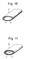
- a branch pipe liner bag 4 shown in Fig. 10, is used.
- This pipe liner bag 4 itself will be first described in detail.
- a rectangular nonwoven resin-absorbent fabric 5 of polyester felt is sewed into a tubular shape.
- the tubular fabric 5 is then externally coated with an air- and water-tight plastic film 6 and is soaked with a thermosetting resin.
- This hermetic film 6 may be made of polyurethane, polyethylene, polyethylene/nylon co-polymer, or polyvinyl chloride resin, and the fabric 5 may be made of polyester, polypropylene, or acrylic resin.
- the tubular pipe liner bag 4 to be inserted in the branch pipe 3 has its tail end closed, and the front end everted and anchored sealingly about the outside of the bottom rim of a tubular pressure cap 7a of a frame 7 installed on the ground.
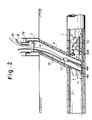
- the length of the liner bag 4 is so designed that when the entire length of the bag 4 is everted without being stopped the head of the thoroughly everted bag 4 would extend beyond the port of the main pipe 1 by at least one meter. Therefore, when the liner bag 4 is everted down the branch pipe 3, the everting head of the liner bag 4 will hit upon the inner wall of the main pipe 1, as shown in Fig. 2, for even when the diameter of the the main pipe 1 is greater than one meter the liner bag 4 would more or less expand lengthwise as it is pressed down. Thus, the eversion of the liner bag 4 is stopped and some portion 4a of the liner bag 4 remains uneverted.
- an on-the-sleigh robot 9 is introduced in the main pipe 1, as shown in Fig. 2.
- Pull ropes are tied to this robot 9 to pull it in either direction in the main pipe 1.
- the robot 9 is equipped with a hydraulically-operated cutter and a hydraulically-operated piston cylinder 10.
- the piston cylinder 10 is operated to throw out its piston rod 10a to push the head 4b of the liner bag 4 leftward, as seen in Fig.
- Method (a) of Fig. 9 utilizes a pull rope 11 with a hook block 12 tied halfway to it, and this rope is passed through the main pipe 1 before the liner bag 4 is inserted in the branch pipe 3.
- the rope 11 is pulled downstream and the hook block 12 engages with the head 4b to dislocate and turn it.
- Method (b) utilizes an air bag 13 and a pull rope 14, and when the head 4b of the everted liner bag 4 lands on the air bag 13, the air bag 13 is inflated and the rope 14 is pulled downstream together with the air bag 13 and the head 4b is dislocated and turned.
- Method (c) utilizes a pressurized flow of a fluid such as water or air.
- a fluid such as water or air.
- reference numeral 15 designates a hot water hose.
- One end of the hot water hose 15 is tied to a rope 16, which is passed through a ring 17 provided at the tail end of the uneverted portion 4a of the liner bag 4, and the free end of which is retained on the ground.
- the rope 16 is pulled up so that the hose 15 is drawn into the everted liner bag 4.
- the free end of the rope 16 is pulled up so that the hot water hose 15 is drawn deep to almost reach the ring 17 provided at the tail end of the liner bag 4, and so as not to allow the hose 15 to recede, the ringed free end of the rope 16 is hooked on a hook 21 provided on the inner wall of the pressure cap 7a, as shown in Fig. 3.
- the open top of the pressure cap 7a of the frame 7 is closed with a lid 22 so that an air space 23 is enclosed defined by the pressure cap 7a, the branch pipe liner bag 4 and the hot water.
- An air hose 24 leading out from an air compressor 25 is inserted in a port of the lid 22 to communicate the air space 23 with the air compressor 25.
- Another hole of the lid 22 has inserted therein a pressure gauge 26, as shown in Fig. 3.
- the compressor 25 is operated to force air into the air space 23 and the pressure on the water in the liner bag 4 is maintained at a constant value so that the bag 4 is kept inflated and pressed against the inner wall of the branch pipe 3, as shown in Fig. 3.
- the hot water heated in a boiler 18 installed on the ground is forced into the hot water hose 15 by means of a hot water pump 19 and is supplied into the branch pipe liner bag 4.
- the hot water is drawn up into another hot water hose 20 and returned to the boiler 18, where the lukewarm water is heated up again.
- the heated water is sent back to the branch pipe liner bag 4 to cure the thermosetting resin soaked in the thickness of the branch pipe liner bag 4, and this circulation is continued until the liner bag 4 is sufficiently heated.
- the hot water hose 15 can be drawn as deep as the head portion 4b of the liner bag 4 so that the hot water circulates well into the head portion of the liner bag 4; as a result, the head portion 4b cures thoroughly and uniformly and there occur no incompletely cured regions.
- the air compressor 25 is operated to increase its force with which the air is supplied to the air space 23 via the air hose 24; as a result the pressure in the air space 23 is increased and the pressure on the water in the liner bag 4 is heightened so much so that the hot water in the branch pipe liner bag 4 is forced to flow backward in the hot water hose 15 and is discharged on the ground, and this operation of the air compressor 25 is continued until the last of the water in the branch pipe liner bag 4 is forced out.
- the on-the-sleigh robot 9 is equipped with a hydraulically-operated motor 27, a TV camera 28, etc., and the unnecessary portion of the branch pipe liner bag 4 is cut off by a rotary cutter 29 which is locked about the output shaft of the motor 27.
- the operator on the ground causes the robot 9 to move to and fro by pulling and letting go pull ropes 30 until the robot 9 assumes a desirable position relative to the unnecessary portion of the liner bag 4; then, the rotary cutter 29 is turned at a high speed and the robot 9 is pulled downstream slowly, whereupon the cutter 29 cuts the unnecessary portion of the liner bag 4, and this cutting is continued until the last remnant of the unnecessary portion is removed. Since there is no uncured gluey region in the branch pipe liner bag 4, the saw teeth of the cutter 29 do not clog, and hence the cutting operation can be conducted easily and smoothly.
- the branch pipe 3 is lined in accordance with the method of the invention after the main pipe 1 is lined beforehand. Since the inner wall of the main pipe 1 is covered with the plastic film 2, the head of the everted liner bag 4 does not stick to the inner wall of the main pipe 1, when it hits upon the inner wall of the main pipe 1, owing to the surface releasability of the plastic film 2.
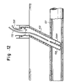
- Fig. 11 is a sectional perspective view of a branch pipe liner bag 34 before eversion, and the branch pipe liner bag 34 is internally coated with a highly impermeable barrier film 35.
- reference numeral 5 designates a tubular nonwoven resin-absorbent fabric of polyester felt, and, like that of the branch pipe liner bag 4, this fabric is impregnated with thermosetting resin.
- the branch pipe liner bag 34 when everted will have a non-adhesive external surface consisting of the barrier film 35, so that the eversion head of the branch pipe liner bag 34 does not stick to the inner wall of the main pipe 1. Thus, the unnecessary portion of the everted liner bag 34 will be easily removed.
- the branch pipe liner bag will be kept from everting as its eversion head is stopped by the inner wall of the main pipe, the eversion head is forced to turn downstream, so that the branch pipe liner bag can be eventually everted completely. Therefore, no portion of the liner bag will remain uneverted.
- hot water for example, is supplied into the branch pipe liner bag which has been inserted in the branch pipe as described above, the hot water will circulate well into the fore end of the liner bag and cause the thermosetting resin soaked in the liner bag to promptly harden thoroughly and uniformly, so that there occur few regions where the branch pipe liner bag is only partly hardened.
- thermosetting resin may be replaced by another hardenable resin such as photosetting resin.
Landscapes
- Engineering & Computer Science (AREA)
- General Engineering & Computer Science (AREA)
- Mechanical Engineering (AREA)
- Manufacturing & Machinery (AREA)
- Lining Or Joining Of Plastics Or The Like (AREA)
- Protection Of Pipes Against Damage, Friction, And Corrosion (AREA)
Claims (8)
- Procédé de garniture intérieure d'un tuyau en dérivation (3) d'un tuyau principal (1), comprenant les étapes ci-dessous:
(a) préparation d'un sac tubulaire formant garniture (4) en cousant un matériau rectangulaire non tissé absorbeur de résine (5) de manière à lui faire prendre une forme tubulaire, avec une extrémité fermée, et en le découpant à une longueur sensiblement supérieure à la longueur du tuyau en dérivation devant être garni intérieurement: (b) fixation d'un film plastique imperméable au-dessus de la surface externe dudit sac tubulaire formant garniture; (c) imprégnation dudit matériau non tissé absorbeur de résine d'une résine fluide durcissable; (d) retournement dudit sac formant garniture dans le tuyau en dérivation, du sol jusqu'au tuyau principal par l'intermédiaire d'une pression de fluide jusqu'à ce que la tête retournée (4b) du sac formant garniture est arrêtée par la paroi interne du tuyau principal; (e) poussée de ladite tête retournée du sac formant garniture pour la faire tourner vers l'aval dans le tuyau principal, permettant ainsi le retournement complet du sac formant garniture; (f) durcissement de ladite résine fluide durcissable tout en gonflant ledit sac formant garniture par l'intermédiaire de la pression de fluide; et (g) enlèvement de la partie dudit sac formant garniture qui déborde dans ledit tuyau principal. - Procédé selon la revendication 1, caractérisé en ce qu'avant l'étape (d); le tuyau principal (1) est d'abord revêtu d'une garniture intérieure (2) et en ce que la partie de la garniture fermant le trou menant vers le tuyau en dérivation (3) est enlevée.
- Procédé selon les revendications 1 ou 2, caractérisé en ce que la surface interne dudit sac formant garniture (4) est recouverte d'un film de barrière imperméable avant le retournement.
- Procédé selon l'une quelconque des revendications 1 à 3, caractérisé en ce que lors de l'étape (g) l'enlèvement de ladite partie du sac formant garniture (4) est réalisé par l'intermédiaire d'une cisaille circulaire (29). entraînée par un moteur (27) et installée sur un robot (9) pouvant aller et venir librement dans le tuyau principal (1).
- Procédé selon l'une quelconque des revendications 1 à 4, caractérisé en ce que lors de l'étape (e) un câble de traction (11) comportant un bloc à crochet (12), qui y est fixé au milieu, est auparavant passé dans le tuyau principal (1), de sorte que la tête retournée (4b) du sac formant garniture (4) atterrit sur le câble en un emplacement situé en aval par rapport au bloc à crochet, le câble de traction étant tiré vers l'aval pour faire tourner la tête retournée.
- Procédé selon l'une quelconque des revendications 1 à 4, caractérisé en ce que lors de l'étape (e) un câble de traction (14) comportant un sac à air (13), attaché en son milieu, est passé auparavant dans le tuyau principal (1), de sorte que la tête retournée (4b) du sac formant garniture (4) atterrit sur le sac à air, le câble de traction étant tiré vers l'aval après le gonflement du sac à air, de sorte faire tourner la tête retournée.
- Procédé selon l'une quelconque des revendications 1 à 4, caractérisé en ce que lors de l'étape (e) un écoulement de fluide sous pression est appliqué en aval sur la tête retournée (4b), pour faire tourner la tête retournée.
- Procédé selon l'une quelconque des revendications 1 à 7, caractérisé en ce que ladite résine fluide durcissable est une résine thermodurcissable.
Applications Claiming Priority (2)
| Application Number | Priority Date | Filing Date | Title |
|---|---|---|---|
| JP5021431A JPH0775866B2 (ja) | 1993-02-09 | 1993-02-09 | 枝管ライニング工法 |
| JP21431/93 | 1993-02-09 |
Publications (2)
| Publication Number | Publication Date |
|---|---|
| EP0610620A1 EP0610620A1 (fr) | 1994-08-17 |
| EP0610620B1 true EP0610620B1 (fr) | 1996-09-04 |
Family
ID=12054803
Family Applications (1)
| Application Number | Title | Priority Date | Filing Date |
|---|---|---|---|
| EP93308428A Expired - Lifetime EP0610620B1 (fr) | 1993-02-09 | 1993-10-22 | Une méthode pour gainage d'une conduite latérale |
Country Status (7)
| Country | Link |
|---|---|
| US (1) | US5356502A (fr) |
| EP (1) | EP0610620B1 (fr) |
| JP (1) | JPH0775866B2 (fr) |
| KR (1) | KR0178145B1 (fr) |
| DE (1) | DE69304509T2 (fr) |
| DK (1) | DK0610620T3 (fr) |
| MY (1) | MY109465A (fr) |
Families Citing this family (20)
| Publication number | Priority date | Publication date | Assignee | Title |
|---|---|---|---|---|
| US5674030A (en) * | 1991-08-27 | 1997-10-07 | Sika Equipment Ag. | Device and method for repairing building branch lines in inacessible sewer mains |
| JP2530552B2 (ja) * | 1993-03-23 | 1996-09-04 | 株式会社湘南合成樹脂製作所 | 枝管ライニング工法 |
| JP2702086B2 (ja) * | 1995-02-13 | 1998-01-21 | 株式会社湘南合成樹脂製作所 | 管ライニング材の製造方法 |
| JP2719312B2 (ja) * | 1995-03-23 | 1998-02-25 | 株式会社湘南合成樹脂製作所 | 管ライニング材の接合方法 |
| GB9507003D0 (en) * | 1995-04-05 | 1995-05-31 | Rice Nigel | Sewer re-lining |
| GB9510433D0 (en) * | 1995-05-22 | 1995-07-19 | British Gas Plc | Installing pipes |
| JP2667796B2 (ja) * | 1995-07-07 | 1997-10-27 | 株式会社湘南合成樹脂製作所 | 管ライニング工法 |
| US5879501A (en) * | 1996-12-19 | 1999-03-09 | Illinois Tool Works, Inc. | Method of sealing sewer systems |
| CA2354226A1 (fr) | 2001-01-31 | 2002-07-31 | Cal Holland | Appareil robotique et methode d'entretien non destructif de canalisations croisees |
| US20050281970A1 (en) * | 2004-06-16 | 2005-12-22 | Lamarca Louis J Ii | Lateral liner substrates |
| TW200613677A (en) * | 2004-10-27 | 2006-05-01 | Shonan Gosei Jushi Seisakusho | Lateral pipe lining material and lateral pipe lining method |
| JP2007283572A (ja) * | 2006-04-14 | 2007-11-01 | Shonan Plastic Mfg Co Ltd | 管ライニング工法 |
| JP2008162033A (ja) * | 2006-12-27 | 2008-07-17 | Shikoku Kankyo Seibi Kogyo Kk | 枝管のライニング材、及び枝管のライニング処理方法 |
| JP2008238657A (ja) * | 2007-03-28 | 2008-10-09 | Shonan Plastic Mfg Co Ltd | 電熱装置およびそれを用いた管路ライニング工法 |
| WO2016087707A1 (fr) * | 2014-12-04 | 2016-06-09 | Consti Talotekniikka Oy | Procédé permettant de rénover un point de branchement dans une canalisation en cours de rénovation |
| EP3156710B1 (fr) | 2015-10-14 | 2018-12-12 | ULC Robotics, Inc. | Procédé de mesure de distance dans un pipeline |
| CN105697933B (zh) * | 2016-03-29 | 2017-10-27 | 华北水利水电大学 | 雨污水管线防渗漏装置、其制造方法以及其使用方法 |
| KR102239106B1 (ko) * | 2020-09-04 | 2021-04-12 | 이수기공(주) | Pe 라이닝에 의한 분기관 갱생단계를 포함한 노후관 갱생 방법 |
| DE102022121917A1 (de) * | 2022-08-30 | 2024-02-29 | Brawo Systems Gmbh | Vorrichtung und Verfahren zum Aushärten eines in einem Inversionsverfahren in ein Rohr eingezogenen Liners |
| WO2024153398A1 (fr) * | 2023-01-19 | 2024-07-25 | British Telecommunications Public Limited Company | Appareil, système et procédé destinés à être utilisés avec des tunnels utilitaires |
Family Cites Families (13)
| Publication number | Priority date | Publication date | Assignee | Title |
|---|---|---|---|---|
| US4366012A (en) * | 1981-02-05 | 1982-12-28 | Insituform International Inc. | Impregnation process |
| US4434115A (en) * | 1981-02-18 | 1984-02-28 | Insituform International, Inc. | Method for remote lining of side connections |
| GB8400233D0 (en) * | 1984-01-05 | 1984-02-08 | Edgealpha Ltd | Lining pipelines and passageways |
| GB8407706D0 (en) * | 1984-03-24 | 1984-05-02 | Edgealpha Ltd | Lining pipelines in passageways |
| GB2157796B (en) * | 1984-04-17 | 1987-07-08 | Nigel Rice | Sewer relining |
| JPS61100437A (ja) * | 1984-10-24 | 1986-05-19 | Osaka Gas Co Ltd | 都市ガス導管における分岐管ライニング方法 |
| GB8609307D0 (en) * | 1986-04-16 | 1986-05-21 | Insituform Group Ltd | Lining of piplines |
| JPS63286326A (ja) * | 1987-05-20 | 1988-11-24 | Toubu Kuriinaa Service:Kk | 枝管補修工法 |
| JPH0198325A (ja) * | 1987-10-09 | 1989-04-17 | Mazda Motor Corp | 車載用受信装置 |
| GB2213230B (en) * | 1987-12-28 | 1992-05-06 | Osaka Bosui Kensetsusha Kk | Method of lining branch pipe portion of underground main pipe with rigid plastics tube |
| JPH0717012B2 (ja) * | 1989-09-05 | 1995-03-01 | 東京瓦斯株式会社 | 導管の非掘削チューブ反転ライニング工法 |
| US5108533A (en) * | 1989-10-10 | 1992-04-28 | Long Technologies, Inc. | Method and combination for installing a liner within a service pipe transversely connected to a main pipe |
| JPH07121552B2 (ja) * | 1991-05-31 | 1995-12-25 | 株式会社ゲット | 枝管ライニング工法 |
-
1993
- 1993-02-09 JP JP5021431A patent/JPH0775866B2/ja not_active Expired - Fee Related
- 1993-07-12 KR KR1019930013042A patent/KR0178145B1/ko not_active Expired - Fee Related
- 1993-10-22 US US08/139,671 patent/US5356502A/en not_active Expired - Fee Related
- 1993-10-22 DK DK93308428.7T patent/DK0610620T3/da active
- 1993-10-22 EP EP93308428A patent/EP0610620B1/fr not_active Expired - Lifetime
- 1993-10-22 DE DE69304509T patent/DE69304509T2/de not_active Expired - Fee Related
- 1993-12-11 MY MYPI93002675A patent/MY109465A/en unknown
Also Published As
| Publication number | Publication date |
|---|---|
| KR0178145B1 (ko) | 1999-05-15 |
| MY109465A (en) | 1997-01-31 |
| JPH0775866B2 (ja) | 1995-08-16 |
| KR940019448A (ko) | 1994-09-14 |
| US5356502A (en) | 1994-10-18 |
| DK0610620T3 (da) | 1996-09-23 |
| DE69304509T2 (de) | 1997-02-20 |
| DE69304509D1 (de) | 1996-10-10 |
| EP0610620A1 (fr) | 1994-08-17 |
| JPH06234160A (ja) | 1994-08-23 |
Similar Documents
| Publication | Publication Date | Title |
|---|---|---|
| EP0610620B1 (fr) | Une méthode pour gainage d'une conduite latérale | |
| EP0620102B1 (fr) | Méthode de revêtement et revêtement pour tuyaux de dérivation | |
| US5454401A (en) | Method of lining a branch pipe | |
| EP0752305B1 (fr) | Procédé pour revêtir l'intérieur d'un tuyau coudé | |
| EP0624749B1 (fr) | Procédé de réparation de conduites | |
| US6024910A (en) | Method for lining a tubular conduit | |
| US5329063A (en) | Liner assembly for lining branch pipes and a method for manufacturing the liner assembly | |
| US6056017A (en) | Pipe lining method | |
| US5490964A (en) | Method and device for repairing a tubular conduit | |
| US6206993B1 (en) | Method and apparatus for providing a tubular material within a pipeline | |
| EP0978681B1 (fr) | Revêtement pour une conduite de dérivation et procédé de revêtement d'une conduite de dérivation | |
| EP0620104A2 (fr) | Revêtement pour tuyaux, sa méthode de fabrication et méthode de réparation de tuyaux d'écoulement | |
| US6682668B1 (en) | Installation of cured in place liners with an endless reusable inflation bladder and installation apparatus | |
| US5486332A (en) | Method for everting a tubular liner bag | |
| EP0704294A2 (fr) | Procédé de revêtement d'un trou d'homme | |
| EP0620101B1 (fr) | Procédé et appareil pour le revêtement d'un tuyau de dérivation | |
| EP0797042B1 (fr) | Dispositif et procédé de revêtement d'une conduite enterrée | |
| KR19990013994A (ko) | 지관개구부 표적용 지그 및 관라이닝공법 | |
| EP0911568A2 (fr) | Dispositif de revêtement d'un tuyau de dérivation et procédé pour le revêtement d'un tuyau |
Legal Events
| Date | Code | Title | Description |
|---|---|---|---|
| PUAI | Public reference made under article 153(3) epc to a published international application that has entered the european phase |
Free format text: ORIGINAL CODE: 0009012 |
|
| AK | Designated contracting states |
Kind code of ref document: A1 Designated state(s): DE DK FR GB |
|
| 17P | Request for examination filed |
Effective date: 19950124 |
|
| 17Q | First examination report despatched |
Effective date: 19950921 |
|
| GRAH | Despatch of communication of intention to grant a patent |
Free format text: ORIGINAL CODE: EPIDOS IGRA |
|
| GRAH | Despatch of communication of intention to grant a patent |
Free format text: ORIGINAL CODE: EPIDOS IGRA |
|
| GRAA | (expected) grant |
Free format text: ORIGINAL CODE: 0009210 |
|
| AK | Designated contracting states |
Kind code of ref document: B1 Designated state(s): DE DK FR GB |
|
| REG | Reference to a national code |
Ref country code: DK Ref legal event code: T3 |
|
| REF | Corresponds to: |
Ref document number: 69304509 Country of ref document: DE Date of ref document: 19961010 |
|
| ET | Fr: translation filed |
Free format text: CORRECTIONS |
|
| PLBE | No opposition filed within time limit |
Free format text: ORIGINAL CODE: 0009261 |
|
| 26N | No opposition filed | ||
| PGFP | Annual fee paid to national office [announced via postgrant information from national office to epo] |
Ref country code: FR Payment date: 20011010 Year of fee payment: 9 |
|
| PGFP | Annual fee paid to national office [announced via postgrant information from national office to epo] |
Ref country code: DK Payment date: 20011012 Year of fee payment: 9 |
|
| PGFP | Annual fee paid to national office [announced via postgrant information from national office to epo] |
Ref country code: GB Payment date: 20011024 Year of fee payment: 9 |
|
| PGFP | Annual fee paid to national office [announced via postgrant information from national office to epo] |
Ref country code: DE Payment date: 20011105 Year of fee payment: 9 |
|
| REG | Reference to a national code |
Ref country code: GB Ref legal event code: IF02 |
|
| PG25 | Lapsed in a contracting state [announced via postgrant information from national office to epo] |
Ref country code: GB Free format text: LAPSE BECAUSE OF NON-PAYMENT OF DUE FEES Effective date: 20021022 |
|
| PG25 | Lapsed in a contracting state [announced via postgrant information from national office to epo] |
Ref country code: DK Free format text: LAPSE BECAUSE OF NON-PAYMENT OF DUE FEES Effective date: 20021031 |
|
| PG25 | Lapsed in a contracting state [announced via postgrant information from national office to epo] |
Ref country code: DE Free format text: LAPSE BECAUSE OF NON-PAYMENT OF DUE FEES Effective date: 20030501 |
|
| REG | Reference to a national code |
Ref country code: DK Ref legal event code: EBP |
|
| GBPC | Gb: european patent ceased through non-payment of renewal fee |
Effective date: 20021022 |
|
| PG25 | Lapsed in a contracting state [announced via postgrant information from national office to epo] |
Ref country code: FR Free format text: LAPSE BECAUSE OF NON-PAYMENT OF DUE FEES Effective date: 20030630 |
|
| REG | Reference to a national code |
Ref country code: FR Ref legal event code: ST |