EP0611045B1 - Assemblage pour l'extension de panneaux séparateurs - Google Patents
Assemblage pour l'extension de panneaux séparateurs Download PDFInfo
- Publication number
- EP0611045B1 EP0611045B1 EP94300399A EP94300399A EP0611045B1 EP 0611045 B1 EP0611045 B1 EP 0611045B1 EP 94300399 A EP94300399 A EP 94300399A EP 94300399 A EP94300399 A EP 94300399A EP 0611045 B1 EP0611045 B1 EP 0611045B1
- Authority
- EP
- European Patent Office
- Prior art keywords
- wall panel
- extension
- assembly
- panel
- base
- Prior art date
- Legal status (The legal status is an assumption and is not a legal conclusion. Google has not performed a legal analysis and makes no representation as to the accuracy of the status listed.)
- Expired - Lifetime
Links
- 238000009432 framing Methods 0.000 claims 2
- 238000003780 insertion Methods 0.000 description 3
- 230000037431 insertion Effects 0.000 description 3
- 239000000463 material Substances 0.000 description 3
- 229910052782 aluminium Inorganic materials 0.000 description 2
- XAGFODPZIPBFFR-UHFFFAOYSA-N aluminium Chemical compound [Al] XAGFODPZIPBFFR-UHFFFAOYSA-N 0.000 description 2
- 238000000034 method Methods 0.000 description 2
- 230000002093 peripheral effect Effects 0.000 description 2
- 239000004033 plastic Substances 0.000 description 2
- 230000000712 assembly Effects 0.000 description 1
- 238000000429 assembly Methods 0.000 description 1
- 238000010276 construction Methods 0.000 description 1
- 229910003460 diamond Inorganic materials 0.000 description 1
- 239000010432 diamond Substances 0.000 description 1
- 238000001125 extrusion Methods 0.000 description 1
- 238000009434 installation Methods 0.000 description 1
- 229910052751 metal Inorganic materials 0.000 description 1
- 239000002184 metal Substances 0.000 description 1
- 239000012858 resilient material Substances 0.000 description 1
- 238000003466 welding Methods 0.000 description 1
- 239000002023 wood Substances 0.000 description 1
Images

Classifications
-
- E—FIXED CONSTRUCTIONS
- E04—BUILDING
- E04B—GENERAL BUILDING CONSTRUCTIONS; WALLS, e.g. PARTITIONS; ROOFS; FLOORS; CEILINGS; INSULATION OR OTHER PROTECTION OF BUILDINGS
- E04B2/00—Walls, e.g. partitions, for buildings; Wall construction with regard to insulation; Connections specially adapted to walls
- E04B2/74—Removable non-load-bearing partitions; Partitions with a free upper edge
- E04B2/7407—Removable non-load-bearing partitions; Partitions with a free upper edge assembled using frames with infill panels or coverings only; made-up of panels and a support structure incorporating posts
- E04B2/7416—Removable non-load-bearing partitions; Partitions with a free upper edge assembled using frames with infill panels or coverings only; made-up of panels and a support structure incorporating posts with free upper edge, e.g. for use as office space dividers
-
- E—FIXED CONSTRUCTIONS
- E04—BUILDING
- E04B—GENERAL BUILDING CONSTRUCTIONS; WALLS, e.g. PARTITIONS; ROOFS; FLOORS; CEILINGS; INSULATION OR OTHER PROTECTION OF BUILDINGS
- E04B2/00—Walls, e.g. partitions, for buildings; Wall construction with regard to insulation; Connections specially adapted to walls
- E04B2/74—Removable non-load-bearing partitions; Partitions with a free upper edge
- E04B2/7407—Removable non-load-bearing partitions; Partitions with a free upper edge assembled using frames with infill panels or coverings only; made-up of panels and a support structure incorporating posts
- E04B2/7448—Removable non-load-bearing partitions; Partitions with a free upper edge assembled using frames with infill panels or coverings only; made-up of panels and a support structure incorporating posts with separate framed panels without intermediary posts, extending from floor to ceiling
Definitions
- the present invention relates generally to wall panel systems. More particularly, the invention relates to a panel extension assembly that allows for a previously constructed wall panel to have an additional wall panel stacked on top thereby increasing the height of the wall.
- modular vertical wall panel systems are often used to divide an enclosed space into separate work areas. These work areas are often constructed using panels of a standard size. For example, an office may use a standard panel system that has a height of 0.914m (36 inches). Wall panel systems constructed with 0.914m (36 inch) wall panels are particularly useful in creating secreterial stations, and the like. While, taller wall panel systems create a more private work area such as that required in telephone sales. However, if a business desired to switch between an original shorter panel system and a larger wall panel system, it would have to completely remove the original wall panel system and replace it with taller vertical panels.
- U.S. Patent No. 4,407,101 discloses a vertically adjustable wall panel.
- An adjustment bolt connects one end of the wall panel to a foot assembly.
- the adjustment bolt is externally threaded in opposite directions so that when the bolt is turned, the wall panel moves vertically relative to the foot assembly.
- elongated covers are pivotally attached to the wall panel.
- this device fails to provide an office wall panel system that is easily extended to a new height. Therefore, a simple and more versatile panel extension mechanism is needed.
- a panel extension assembly for supporting an extension wall panel on top of a base wall panel, the base wall panel being encased in a frame including a top member having a substantially horizontally extending top surface and a pair of spaced side surfaces, said panel extension assembly comprising: a channel member adapted to receive said top member of said base wall panel frame, said channel member having a pair of spaced side walls joined by a middle wall adapted to slide over said side surfaces of said top member and rest on said top surface; an extension member attached to said channel member and extending upward therefrom; and an extension wall panel attached to said extension member whereby said extension wall panel is securely positioned on top of said base wall panel.
- Embodiments of the present invention provide significant advantages over other wall panel assemblies.
- these embodiments provide a simple and more versatile panel extension capable of easily extending the height of an associated base wall panel assembly.
- the panel extension assembly provides for a secure and aesthetically pleasing wall panel assembly which does not leave open areas at the base of the assembly.
- Embodiments of the invention are more efficient and versatile than the prior art.
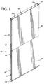
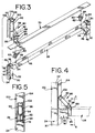
- Figures 1-5 show a preferred embodiment of the wall panel assembly 10 and panel extension assembly 11 of the present invention.
- the wall panel assembly 10 is shown with a base wall panel assembly 12 having a base wall panel 13 and a panel extension assembly 11 with an extension wall panel 15.
- the panels 13 and 15 may be constructed from wood, plastic, metal or any other materials used in constructing modular walls. Similarly, the panels 13 and 15 may be provided with any external aesthetic characteristics that are desired.
- the peripheral base wall panel frame 20 encasing the base wall panel 13 has a base support element 22, a first vertically extending side member 24, a second vertically extending side member 26 interconnected by a horizontally extending top member 28.
- the first side member 24, the second side member 26 and the top member 28 form a substantially horizontally extending top surface for the base frame 20.
- the vertically extending base wall panel 13 is attached to the first side member 24, the second side member 26 and the top member 28.
- the base wall panel 13 and base wall panel frame 20 may be those such as the Ethospace frame and panels manufactured by Herman Miller, Inc.
- the first side member 24 and the second side member 26 have a front surface 30, a back surface 32, a first side surface 34 and a second side surface 36 defining a cavity 38 therein.
- the side members 24 and 26 have a plurality of vertically aligned hook members 40 extending outward from the first side member 24 and the second side member 26 in order to mate with slots (not shown) in the side members of an adjacent wall panel assembly.
- the first side member 24 and the second side member 26 have a series of slots which mate with the hook members 40 of an adjacent side member.
- a series of rectangular slots 42 are defined by the front surface 30 and the back surface 32 to provide a connection for a perpendicularly extending wall panel assembly.
- the side members 24 and 26 have a relatively narrow channel 44 extending outward from each side member. The channel 44 is sized to securely mate with the edge of an adjacent wall panel thereby better securing the adjacent wall panel.
- a horizontally extending top member 28 of the peripheral frame 20 is connected to the first side surface 34 of the first side member 24 and second side member 26.
- the cop member 28 defines a cavity running therein.
- a first wall 46 of the top member 28 has apertures 48 sized to allow clips 60 to fit therein.
- the clips 60 have a resilient diamond shaped lower surface 62 extending from two projecting surfaces 64.
- the clips 60 are made from a resilient material such as plastic or the like. The resilient nature of the lower surface 62 of the clips 60 facilitates their insertion within the apertures 48 of the top member 28.
- the projecting surfaces 64 of the clips 60 engage a channel (not shown) in a cover member 70.
- the cover member 70 is attached to the top member 28 to provide an aesthetically pleasing top surface for the assembly.
- a panel extension bracket 80 has a substantially U-shaped channel member 82 with a first side wall 84 and a second side wall 86 connected by a middle wall 88.
- the channel member 82 is sized to mate with the top member 28 of the base frame 20.
- Two apertures 90 are provided in each of the side walls 84 and 86 of the channel member 82.
- carriage bolts (one shown) 91 extend horizontally through apertures 90 of the first side wall 84, the base wall panel 13 and through the apertures 90 of the second side wall 86. Nuts are attached to the threaded portions of the bolts 91 extending out the apertures 90 of the second side wall 86.
- an aperture 92 is located in the middle wall 88 of the channel member 82 to further secure the panel extension bracket 80.
- a carriage bolt 94 extends downward through the aperture 92 and the top member 28 of the base frame 20.
- a nut is attached to the threaded portion of the bolt 94 extending out a bottom surface 95 of the top member 28 of the base wall panel frame 20.
- the panel extension bracket 80 further includes a pair of spaced parallel side sections 96 extending upward from the channel member 82.
- the side sections 96 slope upwardly from the top member 28 of the base frame 20 to the extension member 100 thereby forming a substantially triangular shape.
- a vertically extending flange 102 runs between the two side sections 96 thereby connecting the side surfaces 96.
- the flange 102 is connected to the front wall 104 of the extension member 100.
- the extension member 100 extends upward from the channel member 82 and directly above a side member of the base frame 20.
- the height of the frame member 100 may be adjusted to correspond with the height of an associated panel, although 0.813m (32 inches) is the preferred height.
- a vertically extending cavity 105 runs in the extension member 100.
- a J-shaped channel 108 runs up a first side wall 110 of the extension member 100. The channel 108 is sized to mate with an adjacent extension panel thereby better securing the adjacent extension panel.
- a front wall 112 and a back wall 114 of the extension 100 have apertures (not shown) for insertion of a fastening means such as a screw, bolt or the like that provides for a secure engagement between the extension wall panel 15 and the extension member 100.
- a cap member 120 extends horizontally across the top surface 122 of the extension wall panel 15.
- the cap member 120 has an aperture 124 sized for the insertion of a fastening mechanism such as a screw, bolt or the like.
- the fastening mechanism serves to secure the cap member 120 against the extension member 100 and the extension wall panel 15.
- Second apertures 126 in the cap member 120 similarly serve to receive a fastening mechanism such as a screw, bolt or the like thereby securing the cap member 120 against the extension wall panel 15.
- the cap member 120 may be constructed from materials such as aluminum or the like.
- the above described panel extension bracket 80 may be made from individual pieces joined together through welding or the like.
- the upwardly extending flange 102 and the side sections 96 may be welded to the frame member 100.
- the panel extension bracket 80 may be made from a one piece construction such as that formed from an extrusion process or a die cast process.
- the panel extension bracket 80 and cap member 120 may be from materials such as aluminum or the like.
Landscapes
- Engineering & Computer Science (AREA)
- Architecture (AREA)
- Physics & Mathematics (AREA)
- Electromagnetism (AREA)
- Civil Engineering (AREA)
- Structural Engineering (AREA)
- Finishing Walls (AREA)
- Load-Bearing And Curtain Walls (AREA)
- Panels For Use In Building Construction (AREA)
- Furniture Connections (AREA)
- Residential Or Office Buildings (AREA)
Claims (14)
- Assemblage pour l'extension de panneaux séparateurs (11) pour supporter un panneau séparateur mural d'extension (15) sur la partie supérieure d'un panneau séparateur mural de base (13), le panneau séparateur mural de base (13) étant logé dans un cadre (20) comprenant un élément supérieur (28) ayant une surface supérieure (46) s'étendant sensiblement horizontalement et une paire de surfaces latérales espacées, ledit assemblage pour extension de panneaux séparateurs (11) comprenant : un élément de passage (82) adapté pour recevoir ledit élément supérieur (28) dudit cadre de panneau séparateur de base (20), ledit élément de passage (82) ayant une paire de parois latérales espacées (84, 86) reliées par une paroi centrale (88) adaptée pour coulisser sur lesdites surfaces latérales dudit élément supérieur (28) et reposer sur ladite surface supérieure (46) ; un élément d'extension (100) fixé audit élément de passage (82) et s'étendant vers le haut depuis cet endroit et un panneau séparateur mural d'extension (15) fixé audit élément d'extension (100), moyennant quoi ledit panneau séparateur mural d'extension (15) est placé de manière fixe sur la partie supérieure dudit panneau séparateur mural de base (13).
- Assemblage pour l'extension de panneaux séparateurs (11) selon la revendication 1, comprenant en outre des premiers moyens de fixation qui fixent ledit panneau séparateur mural d'extension (15) audit élément d'extension (100).
- Assemblage pour l'extension de panneaux séparateurs (11) selon la revendication 2, comprenant en outre des seconds moyens de fixation (94) qui fixent ledit élément de passage (82) audit élément supérieur (28) dudit cadre de panneau séparateur mural de base (20).
- Assemblage pour l'extension de panneaux séparateurs (11) selon la revendication 3, dans lequel ladite paroi centrale (88) de chaque dit élément de passage (82) a une ouverture (92) à travers laquelle lesdits seconds éléments de fixation (94) s'étendent en fixant ainsi ledit élément de passage (82) audit élément supérieur (28) dudit cadre de panneau séparateur mural de base (20).
- Assemblage pour l'extension de panneaux séparateurs (11) selon l'une quelconque des revendications précédentes, dans lequel ledit élément de passage (82) a une bride (96) triangulaire s'étendant vers le haut qui relie ledit élément de passage (82) audit élément d'extension (100).
- Assemblage pour l'extension de panneaux séparateurs (11) selon la revendication 5, dans lequel l'élément d'extension (100) a deux parois espacées formant un passage (108) s'étendant verticalement qui reçoit un panneau séparateur mural d'extension attenant (15).
- Assemblage pour l'extension de panneaux séparateurs (11) selon l'une quelconque des revendications précédentes, comprenant en outre un élément formant couvercle (120) fixé à une partie supérieure dudit élément d'extension (100) et s'étendant vers un élément d'extension adjacent, ledit élément formant couvercle (120) entourant une surface (122) dudit panneau séparateur mural (15).
- Assemblage de panneaux séparateurs (10) destiné à être utilisé avec des murs modulaires, ledit assemblage pour l'extension des panneaux séparateurs muraux (10) comprenant un assemblage pour l'extension de panneaux séparateurs (11) selon la revendication 1 et un assemblage de cadre de base (12) ayant un panneau séparateur mural de base (13) fixé à un cadre de panneau séparateur mural de base (20), ledit cadre (20) comprenant un élément de support de base (22) et un élément supérieur (28) espacé dudit élément de support de base (22), ledit élément supérieur (28) ayant une surface supérieure (46) sensiblement horizontale et une paire de surfaces latérales espacées, ledit panneau séparateur mural d'extension (15) étant fixé au-dessus dudit panneau séparateur mural de base (13) de telle sorte que ledit assemblage pour panneaux séparateurs muraux (10) a une hauteur au moins aussi élevée que ledit panneau séparateur mural de base (13) et ledit panneau séparateur mural d'extension (15).
- Assemblage de panneaux séparateurs muraux (10) selon la revendication 8, comprenant en outre une paire de brides (96) latérales espacées parallèlement s'étendant vers le haut dudit élément de passage (82) jusqu'à une surface avant (104) dudit élément d'extension (100).
- Assemblage de panneaux séparateurs muraux (10) selon la revendication 9, dans lequel lesdites brides (96) ont chacune une forme triangulaire.
- Assemblage de panneaux séparateurs muraux (10) selon l'une quelconque des revendications 8 à 10, comprenant en outre un élément formant couvercle (120) fixé à une partie supérieure dudit élément d'extension (100) et s'étendant le long d'une surface supérieure (122) dudit panneau séparateur mural d'extension (15) jusqu'à un élément d'extension adjacent, ledit élément formant couvercle (120) entourant une surface supérieure (122) dudit panneau séparateur mural d'extension (15).
- Assemblage de panneaux séparateurs muraux (10) selon l'une quelconque des revendications 8 à 11, dans lequel ledit panneau séparateur mural de base (13) et ledit panneau séparateur mural d'extension (15) sont coplanaires.
- Assemblage de panneaux séparateurs muraux (10) selon l'une quelconque des revendications 8 à 12, dans lequel ledit ensemble de panneaux séparateurs muraux de base (12) comprend en outre un mécanisme de support pour fixer ledit assemblage de panneaux séparateurs muraux de base (12) dans une orientation verticale.
- Assemblage de panneaux séparateurs muraux (10) selon la revendication 13, dans lequel, à l'intérieur dudit cadre de panneau séparateur mural de base (20), ledit élément supérieur (28) relie ensemble un premier élément latéral (24) s'étendant verticalement et un second élément latéral (26) s'étendant verticalement.
Applications Claiming Priority (2)
| Application Number | Priority Date | Filing Date | Title |
|---|---|---|---|
| US08/017,644 US5394668A (en) | 1993-02-12 | 1993-02-12 | Panel extension assembly |
| US17644 | 1993-02-12 |
Publications (3)
| Publication Number | Publication Date |
|---|---|
| EP0611045A2 EP0611045A2 (fr) | 1994-08-17 |
| EP0611045A3 EP0611045A3 (en) | 1995-11-29 |
| EP0611045B1 true EP0611045B1 (fr) | 2000-09-27 |
Family
ID=21783747
Family Applications (1)
| Application Number | Title | Priority Date | Filing Date |
|---|---|---|---|
| EP94300399A Expired - Lifetime EP0611045B1 (fr) | 1993-02-12 | 1994-01-19 | Assemblage pour l'extension de panneaux séparateurs |
Country Status (7)
| Country | Link |
|---|---|
| US (1) | US5394668A (fr) |
| EP (1) | EP0611045B1 (fr) |
| JP (1) | JPH06248752A (fr) |
| KR (1) | KR940019944A (fr) |
| CA (1) | CA2114867C (fr) |
| DE (1) | DE69425993T2 (fr) |
| ES (1) | ES2149842T3 (fr) |
Families Citing this family (49)
| Publication number | Priority date | Publication date | Assignee | Title |
|---|---|---|---|---|
| US5490357A (en) * | 1994-06-30 | 1996-02-13 | Ub Office Systems Incorporation | Structure room divider height extension |
| US6128873A (en) | 1994-12-30 | 2000-10-10 | Steelcase Development Inc. | Integrated prefabricated furniture system for fitting-out open plan building space |
| US5746034B1 (en) | 1994-12-30 | 2000-10-17 | Steelcase Inc | Partition system |
| US6223485B1 (en) | 1996-06-07 | 2001-05-01 | Herman Miller, Inc. | Wall panel system |
| US5806258A (en) * | 1996-06-07 | 1998-09-15 | Haworth, Inc. | Wall panel system |
| US6167665B1 (en) | 1996-06-07 | 2001-01-02 | Herman Miller, Inc. | Corner post for a wall panel system |
| US6000179A (en) * | 1996-12-13 | 1999-12-14 | Steelcase Inc. | Stacking panel and off-module panel connections |
| US5943834A (en) * | 1996-12-17 | 1999-08-31 | Steelcase Inc. | Partition construction |
| US6047508A (en) * | 1998-03-10 | 2000-04-11 | Steelcase Development Inc. | Wall panel partition system |
| US6115977A (en) * | 1998-09-11 | 2000-09-12 | Krueger International, Inc. | Knock-down panel partition system |
| US6443411B1 (en) * | 1999-01-27 | 2002-09-03 | Bobrick Washroom Equipment, Inc. | Floor anchor bracket for pilaster |
| US6330773B1 (en) | 1999-04-16 | 2001-12-18 | Steelcase Development Corporation | Stacking bracket for partitions |
| US6295764B1 (en) | 1999-06-04 | 2001-10-02 | Herman Miller, Inc. | Stackable wall panel system |
| GB2353541B (en) | 1999-06-04 | 2003-10-15 | Miller Herman Inc | Stackable wall panel system |
| US6351917B1 (en) | 1999-07-30 | 2002-03-05 | Steelcase Development Corporation | Stacking connector for partitions |
| US6460297B1 (en) * | 1999-12-21 | 2002-10-08 | Inter-Steel Structures, Inc. | Modular building frame |
| US6729085B2 (en) | 2001-02-09 | 2004-05-04 | Herman Miller, Inc. | Wall panel system |
| EP1395717A1 (fr) | 2001-06-15 | 2004-03-10 | Kimball International Inc. | Systeme de panneaux muraux plancher/plafond |
| US20030051415A1 (en) * | 2001-06-16 | 2003-03-20 | Matt Remelts | Accessories for a workspace |
| US6751914B2 (en) * | 2002-03-01 | 2004-06-22 | Steelcase Development Corporation | Post and beam furniture system |
| US6807776B2 (en) | 2002-03-29 | 2004-10-26 | Steelcase Development Corporation | Building outfitting system with common accessory-mounting feature |
| WO2003104581A2 (fr) | 2002-06-06 | 2003-12-18 | Kimball International, Inc. | Systeme de cloisons |
| US8393122B2 (en) * | 2002-06-06 | 2013-03-12 | Kimball International, Inc. | Partition system |
| US7223161B2 (en) * | 2004-06-29 | 2007-05-29 | Goei Co., Ltd. | Cutting apparatus with dust discharging |
| CA2516083C (fr) | 2004-08-17 | 2013-03-12 | Dirtt Environmental Solutions Ltd. | Systeme mural reconfigurable integre |
| USRE47132E1 (en) | 2004-08-17 | 2018-11-20 | Dirtt Environmental Solutions, Ltd | Integrated reconfigurable wall system |
| US7334372B2 (en) * | 2004-10-15 | 2008-02-26 | Simpson Strong-Tie Co., Inc. | Top flange hanger with strengthening embossment |
| US8046957B2 (en) * | 2006-11-22 | 2011-11-01 | Steelcase Inc. | Stack-on panel assembly |
| US7841142B2 (en) * | 2006-11-22 | 2010-11-30 | Steelcase Inc. | Stack-on panel assembly |
| BE1019891A5 (nl) | 2011-03-28 | 2013-02-05 | Unilin Bvba | Samengesteld element en rugwandconstructie hierbij toegepast. |
| WO2012173930A2 (fr) | 2011-06-11 | 2012-12-20 | Dirtt Environmental Solutions Inc. | Système d'emboîtement de parois modulaires |
| US9249567B2 (en) | 2011-07-26 | 2016-02-02 | Haworth, Inc. | Reusable architectural wall |
| CA2800414C (fr) | 2011-12-28 | 2016-08-16 | Dirtt Environmental Solutions, Ltd. | Murs modulaires incorporant des meubles encastres et extensibles |
| US9394680B2 (en) | 2013-12-14 | 2016-07-19 | Simpson Strong-Tie Company | Drywall joist hanger |
| WO2015126762A1 (fr) | 2014-02-20 | 2015-08-27 | Dirtt Environmental Solutions Inc. | Procédé de configuration de parois |
| US9206594B1 (en) | 2014-09-04 | 2015-12-08 | Columbia Insurance Company | Hanger with locator tooth |
| US9622570B1 (en) | 2015-02-13 | 2017-04-18 | Steelcase Inc. | Personal workspace assembly |
| USD758777S1 (en) | 2015-02-13 | 2016-06-14 | Steelcase, Inc. | Personal workspace furniture |
| USD778653S1 (en) | 2015-02-13 | 2017-02-14 | Steelcase Inc. | Table top |
| USD758115S1 (en) | 2015-02-13 | 2016-06-07 | Steelcase, Inc. | Personal workspace furniture |
| USD758776S1 (en) | 2015-02-13 | 2016-06-14 | Steelcase, Inc. | Personal workspace furniture |
| CA2932533C (fr) | 2016-02-10 | 2023-10-03 | Dirtt Environmental Solutions, Ltd. | Parois modulaires dotees de mobilier integre et de fonctionnalite d'opposition |
| WO2017214425A1 (fr) | 2016-06-10 | 2017-12-14 | Dirtt Environmental Solutions, Inc. | Système de paroi avec ensemble de montage de dispositif électronique |
| EP3322863A4 (fr) | 2016-06-10 | 2019-05-01 | DIRTT Environmental Solutions, Ltd. | Substrats en verre à technologie d'écran tactile |
| WO2018009936A2 (fr) | 2016-07-08 | 2018-01-11 | Dirtt Environmental Solutions, Inc. | Verre intelligent basse tension |
| US10501933B2 (en) * | 2017-05-26 | 2019-12-10 | Duraframe, LLC | Weather resistant temporary wall system and method |
| US11142902B2 (en) | 2017-06-07 | 2021-10-12 | Simpson Strong-Tie Company, Inc. | Drywall hanger |
| US11225787B2 (en) | 2018-06-06 | 2022-01-18 | Simpson Strong-Tie Company, Inc. | Drywall spacing joist hanger |
| CN219396722U (zh) * | 2023-03-10 | 2023-07-25 | 杭州傲家科技有限公司 | 钢木一体板及文件柜 |
Family Cites Families (26)
| Publication number | Priority date | Publication date | Assignee | Title |
|---|---|---|---|---|
| US1879848A (en) * | 1930-07-22 | 1932-09-27 | Christopher M Horne | Portable transformer and hoist |
| US1931739A (en) * | 1932-04-29 | 1933-10-24 | Joseph J Rutten | Clip for sectional silos |
| US2115625A (en) * | 1937-08-23 | 1938-04-26 | Otis P Fleshman | Hanger |
| BE477989A (fr) * | 1947-06-23 | |||
| US2729411A (en) * | 1953-03-26 | 1956-01-03 | Cahill John Lewis | Adjustable line hanger |
| US3180459A (en) * | 1962-06-12 | 1965-04-27 | Liskey Aluminum | Demountable sectional partition |
| GB1068579A (en) * | 1964-12-01 | 1967-05-10 | British Metal Crates Ltd | Support assembly for shelves and like fittings |
| US3618675A (en) * | 1969-05-07 | 1971-11-09 | American Products Inc | Spring tooth assembly |
| CA955718A (en) * | 1972-03-20 | 1974-10-08 | Claude Alain | System of modular construction and elements therefor |
| US3989398A (en) * | 1975-01-06 | 1976-11-02 | United States Gypsum Company | Clip-on attachment members for structural steel joists |
| US3907445A (en) * | 1975-01-06 | 1975-09-23 | United States Gypsum Co | Self-aligning joist hanger for structural steel framing |
| US4042200A (en) * | 1976-05-06 | 1977-08-16 | Margaret Mae Cooke | Universal mount for splicing tool |
| US4611948A (en) * | 1979-08-09 | 1986-09-16 | Johnson Lawrence N | Boat trailer with pivotal dropped crossbar rolled mounting system |
| US4410158A (en) * | 1980-07-28 | 1983-10-18 | Maffei Eugene R | Over-bed television support frame |
| US4366910A (en) * | 1980-10-27 | 1983-01-04 | Lok-Rak Corporation Of America | Storage rack assembly and method of assembling same |
| US4478019A (en) * | 1981-10-15 | 1984-10-23 | General Partitions Mfg. Corp. | Structural foam partitions |
| US4607422A (en) * | 1981-12-24 | 1986-08-26 | Scaramucci John P | Method for locking a bonnet to a valve body |
| USRE32890E (en) * | 1984-08-15 | 1989-03-21 | Herman Miller, Inc. | Frame connector system |
| US4692056A (en) * | 1986-07-29 | 1987-09-08 | Alperson Joel H | Garments hang-rail coupling |
| JPS642828U (fr) * | 1987-06-18 | 1989-01-10 | ||
| US4932173A (en) * | 1988-07-21 | 1990-06-12 | Simpson Strong-Tie Company, Inc. | Truss clip |
| US4958671A (en) * | 1989-09-12 | 1990-09-25 | Bove Thomas A | Foldable display system with continuous display surface |
| US5092097A (en) * | 1990-09-10 | 1992-03-03 | United Steel Products Co. | Holddown connector |
| US5070666A (en) * | 1990-09-18 | 1991-12-10 | Herman Miller, Inc. | Top cap insert for a wall panel in a space divider system |
| US5109646A (en) * | 1991-05-14 | 1992-05-05 | Simpson Strong-Tie Company, Inc. | Bearing connection |
| US5104252A (en) * | 1991-10-31 | 1992-04-14 | Simpson Strong-Tie Company, Inc. | Hanger connection |
-
1993
- 1993-02-12 US US08/017,644 patent/US5394668A/en not_active Expired - Lifetime
-
1994
- 1994-01-17 KR KR1019940000683A patent/KR940019944A/ko not_active Ceased
- 1994-01-19 EP EP94300399A patent/EP0611045B1/fr not_active Expired - Lifetime
- 1994-01-19 DE DE69425993T patent/DE69425993T2/de not_active Expired - Fee Related
- 1994-01-19 ES ES94300399T patent/ES2149842T3/es not_active Expired - Lifetime
- 1994-02-03 CA CA002114867A patent/CA2114867C/fr not_active Expired - Fee Related
- 1994-02-14 JP JP6017370A patent/JPH06248752A/ja active Pending
Also Published As
| Publication number | Publication date |
|---|---|
| US5394668A (en) | 1995-03-07 |
| DE69425993T2 (de) | 2001-03-08 |
| CA2114867A1 (fr) | 1994-08-13 |
| DE69425993D1 (de) | 2000-11-02 |
| JPH06248752A (ja) | 1994-09-06 |
| KR940019944A (ko) | 1994-09-15 |
| ES2149842T3 (es) | 2000-11-16 |
| EP0611045A3 (en) | 1995-11-29 |
| EP0611045A2 (fr) | 1994-08-17 |
| CA2114867C (fr) | 1997-12-30 |
Similar Documents
| Publication | Publication Date | Title |
|---|---|---|
| US5394668A (en) | Panel extension assembly | |
| US6807776B2 (en) | Building outfitting system with common accessory-mounting feature | |
| US5412912A (en) | Modular slatwall assembly | |
| EP0443202B1 (fr) | Dispositif pour mur de couloir de système de gestion d'espace de travail | |
| US5899035A (en) | Knock-down portable partition system | |
| US6301846B1 (en) | Knock-down portable partition system | |
| US4821477A (en) | Partition panel system | |
| US5067294A (en) | Partition assembly | |
| US6389773B1 (en) | Stackable panel system for modular office furniture | |
| US7096637B2 (en) | Display structure and system | |
| US6550879B1 (en) | Cabinet structure | |
| US5020293A (en) | Decorative panel assembly | |
| US3691709A (en) | Modular partition system | |
| US3570200A (en) | Partition panel structures | |
| US20170354246A1 (en) | Functional rail and worksurface support | |
| US5263295A (en) | Suspended security ceiling system | |
| JPH07229220A (ja) | 間仕切り装置 | |
| JPS6125390Y2 (fr) | ||
| JP2867362B2 (ja) | 柱巻き陳列パネル装置 | |
| JP4173787B2 (ja) | 間仕切パネル装置 | |
| JP3196089B2 (ja) | 天井パネルの取付構造 | |
| JPH0527857Y2 (fr) | ||
| JP2860310B2 (ja) | メッシュフェンス | |
| JPH082257Y2 (ja) | 可動間仕切壁 | |
| KR930003847Y1 (ko) | 이동식 조립주택 골조 |
Legal Events
| Date | Code | Title | Description |
|---|---|---|---|
| PUAI | Public reference made under article 153(3) epc to a published international application that has entered the european phase |
Free format text: ORIGINAL CODE: 0009012 |
|
| AK | Designated contracting states |
Kind code of ref document: A2 Designated state(s): DE ES FR GB IT |
|
| PUAL | Search report despatched |
Free format text: ORIGINAL CODE: 0009013 |
|
| AK | Designated contracting states |
Kind code of ref document: A3 Designated state(s): DE ES FR GB IT |
|
| 17P | Request for examination filed |
Effective date: 19960228 |
|
| 17Q | First examination report despatched |
Effective date: 19961220 |
|
| GRAG | Despatch of communication of intention to grant |
Free format text: ORIGINAL CODE: EPIDOS AGRA |
|
| GRAG | Despatch of communication of intention to grant |
Free format text: ORIGINAL CODE: EPIDOS AGRA |
|
| GRAH | Despatch of communication of intention to grant a patent |
Free format text: ORIGINAL CODE: EPIDOS IGRA |
|
| GRAH | Despatch of communication of intention to grant a patent |
Free format text: ORIGINAL CODE: EPIDOS IGRA |
|
| GRAA | (expected) grant |
Free format text: ORIGINAL CODE: 0009210 |
|
| AK | Designated contracting states |
Kind code of ref document: B1 Designated state(s): DE ES FR GB IT |
|
| REF | Corresponds to: |
Ref document number: 69425993 Country of ref document: DE Date of ref document: 20001102 |
|
| ET | Fr: translation filed | ||
| REG | Reference to a national code |
Ref country code: ES Ref legal event code: FG2A Ref document number: 2149842 Country of ref document: ES Kind code of ref document: T3 |
|
| ITF | It: translation for a ep patent filed | ||
| PGFP | Annual fee paid to national office [announced via postgrant information from national office to epo] |
Ref country code: FR Payment date: 20010102 Year of fee payment: 8 |
|
| PGFP | Annual fee paid to national office [announced via postgrant information from national office to epo] |
Ref country code: DE Payment date: 20010103 Year of fee payment: 8 |
|
| PGFP | Annual fee paid to national office [announced via postgrant information from national office to epo] |
Ref country code: ES Payment date: 20010208 Year of fee payment: 8 |
|
| PLBE | No opposition filed within time limit |
Free format text: ORIGINAL CODE: 0009261 |
|
| STAA | Information on the status of an ep patent application or granted ep patent |
Free format text: STATUS: NO OPPOSITION FILED WITHIN TIME LIMIT |
|
| 26N | No opposition filed | ||
| REG | Reference to a national code |
Ref country code: GB Ref legal event code: IF02 |
|
| PG25 | Lapsed in a contracting state [announced via postgrant information from national office to epo] |
Ref country code: ES Free format text: LAPSE BECAUSE OF NON-PAYMENT OF DUE FEES Effective date: 20020121 |
|
| PG25 | Lapsed in a contracting state [announced via postgrant information from national office to epo] |
Ref country code: DE Free format text: LAPSE BECAUSE OF NON-PAYMENT OF DUE FEES Effective date: 20020801 |
|
| PG25 | Lapsed in a contracting state [announced via postgrant information from national office to epo] |
Ref country code: FR Free format text: LAPSE BECAUSE OF NON-PAYMENT OF DUE FEES Effective date: 20020930 |
|
| REG | Reference to a national code |
Ref country code: FR Ref legal event code: ST |
|
| REG | Reference to a national code |
Ref country code: ES Ref legal event code: FD2A Effective date: 20031122 |
|
| PGFP | Annual fee paid to national office [announced via postgrant information from national office to epo] |
Ref country code: GB Payment date: 20041210 Year of fee payment: 12 |
|
| PG25 | Lapsed in a contracting state [announced via postgrant information from national office to epo] |
Ref country code: IT Free format text: LAPSE BECAUSE OF NON-PAYMENT OF DUE FEES;WARNING: LAPSES OF ITALIAN PATENTS WITH EFFECTIVE DATE BEFORE 2007 MAY HAVE OCCURRED AT ANY TIME BEFORE 2007. THE CORRECT EFFECTIVE DATE MAY BE DIFFERENT FROM THE ONE RECORDED. Effective date: 20050119 |
|
| PG25 | Lapsed in a contracting state [announced via postgrant information from national office to epo] |
Ref country code: GB Free format text: LAPSE BECAUSE OF NON-PAYMENT OF DUE FEES Effective date: 20060119 |
|
| GBPC | Gb: european patent ceased through non-payment of renewal fee |
Effective date: 20060119 |