EP0611079A1 - Dispositif et procédé de soudage de batterie - Google Patents
Dispositif et procédé de soudage de batterie Download PDFInfo
- Publication number
- EP0611079A1 EP0611079A1 EP94300703A EP94300703A EP0611079A1 EP 0611079 A1 EP0611079 A1 EP 0611079A1 EP 94300703 A EP94300703 A EP 94300703A EP 94300703 A EP94300703 A EP 94300703A EP 0611079 A1 EP0611079 A1 EP 0611079A1
- Authority
- EP
- European Patent Office
- Prior art keywords
- battery
- jar
- welding
- cover
- heating
- Prior art date
- Legal status (The legal status is an assumption and is not a legal conclusion. Google has not performed a legal analysis and makes no representation as to the accuracy of the status listed.)
- Granted
Links
- 238000003466 welding Methods 0.000 title claims abstract description 56
- 238000000034 method Methods 0.000 title claims abstract description 25
- 238000003825 pressing Methods 0.000 claims abstract description 17
- 238000010438 heat treatment Methods 0.000 claims description 39
- 239000004033 plastic Substances 0.000 claims description 16
- 229920003023 plastic Polymers 0.000 claims description 16
- 230000000694 effects Effects 0.000 claims description 3
- 239000012530 fluid Substances 0.000 claims description 3
- 230000003213 activating effect Effects 0.000 claims description 2
- 239000002783 friction material Substances 0.000 claims 1
- 239000011324 bead Substances 0.000 abstract description 15
- 230000000712 assembly Effects 0.000 description 8
- 238000000429 assembly Methods 0.000 description 8
- 230000008569 process Effects 0.000 description 5
- 230000009471 action Effects 0.000 description 3
- 238000002844 melting Methods 0.000 description 2
- 230000008018 melting Effects 0.000 description 2
- 239000012768 molten material Substances 0.000 description 2
- 238000009966 trimming Methods 0.000 description 2
- 206010061224 Limb discomfort Diseases 0.000 description 1
- 229910000831 Steel Inorganic materials 0.000 description 1
- QAOWNCQODCNURD-UHFFFAOYSA-N Sulfuric acid Chemical compound OS(O)(=O)=O QAOWNCQODCNURD-UHFFFAOYSA-N 0.000 description 1
- 239000004809 Teflon Substances 0.000 description 1
- 229920006362 Teflon® Polymers 0.000 description 1
- 230000008901 benefit Effects 0.000 description 1
- 230000015572 biosynthetic process Effects 0.000 description 1
- 230000007797 corrosion Effects 0.000 description 1
- 238000005260 corrosion Methods 0.000 description 1
- 239000003792 electrolyte Substances 0.000 description 1
- 239000000463 material Substances 0.000 description 1
- 238000010309 melting process Methods 0.000 description 1
- 230000004048 modification Effects 0.000 description 1
- 238000012986 modification Methods 0.000 description 1
- 230000004044 response Effects 0.000 description 1
- 230000035939 shock Effects 0.000 description 1
- 239000010959 steel Substances 0.000 description 1
- 235000011149 sulphuric acid Nutrition 0.000 description 1
- 239000001117 sulphuric acid Substances 0.000 description 1
- 229920001169 thermoplastic Polymers 0.000 description 1
- 239000004416 thermosoftening plastic Substances 0.000 description 1
Images


Classifications
-
- B—PERFORMING OPERATIONS; TRANSPORTING
- B29—WORKING OF PLASTICS; WORKING OF SUBSTANCES IN A PLASTIC STATE IN GENERAL
- B29C—SHAPING OR JOINING OF PLASTICS; SHAPING OF MATERIAL IN A PLASTIC STATE, NOT OTHERWISE PROVIDED FOR; AFTER-TREATMENT OF THE SHAPED PRODUCTS, e.g. REPAIRING
- B29C65/00—Joining or sealing of preformed parts, e.g. welding of plastics materials; Apparatus therefor
- B29C65/02—Joining or sealing of preformed parts, e.g. welding of plastics materials; Apparatus therefor by heating, with or without pressure
- B29C65/18—Joining or sealing of preformed parts, e.g. welding of plastics materials; Apparatus therefor by heating, with or without pressure using heated tools
- B29C65/24—Joining or sealing of preformed parts, e.g. welding of plastics materials; Apparatus therefor by heating, with or without pressure using heated tools characterised by the means for heating the tool
- B29C65/30—Electrical means
- B29C65/305—Electrical means involving the use of cartridge heaters
-
- B—PERFORMING OPERATIONS; TRANSPORTING
- B29—WORKING OF PLASTICS; WORKING OF SUBSTANCES IN A PLASTIC STATE IN GENERAL
- B29C—SHAPING OR JOINING OF PLASTICS; SHAPING OF MATERIAL IN A PLASTIC STATE, NOT OTHERWISE PROVIDED FOR; AFTER-TREATMENT OF THE SHAPED PRODUCTS, e.g. REPAIRING
- B29C65/00—Joining or sealing of preformed parts, e.g. welding of plastics materials; Apparatus therefor
- B29C65/02—Joining or sealing of preformed parts, e.g. welding of plastics materials; Apparatus therefor by heating, with or without pressure
- B29C65/18—Joining or sealing of preformed parts, e.g. welding of plastics materials; Apparatus therefor by heating, with or without pressure using heated tools
- B29C65/20—Joining or sealing of preformed parts, e.g. welding of plastics materials; Apparatus therefor by heating, with or without pressure using heated tools with direct contact, e.g. using "mirror"
- B29C65/2007—Joining or sealing of preformed parts, e.g. welding of plastics materials; Apparatus therefor by heating, with or without pressure using heated tools with direct contact, e.g. using "mirror" characterised by the type of welding mirror
- B29C65/203—Joining or sealing of preformed parts, e.g. welding of plastics materials; Apparatus therefor by heating, with or without pressure using heated tools with direct contact, e.g. using "mirror" characterised by the type of welding mirror being several single mirrors, e.g. not mounted on the same tool
-
- B—PERFORMING OPERATIONS; TRANSPORTING
- B29—WORKING OF PLASTICS; WORKING OF SUBSTANCES IN A PLASTIC STATE IN GENERAL
- B29C—SHAPING OR JOINING OF PLASTICS; SHAPING OF MATERIAL IN A PLASTIC STATE, NOT OTHERWISE PROVIDED FOR; AFTER-TREATMENT OF THE SHAPED PRODUCTS, e.g. REPAIRING
- B29C65/00—Joining or sealing of preformed parts, e.g. welding of plastics materials; Apparatus therefor
- B29C65/02—Joining or sealing of preformed parts, e.g. welding of plastics materials; Apparatus therefor by heating, with or without pressure
- B29C65/18—Joining or sealing of preformed parts, e.g. welding of plastics materials; Apparatus therefor by heating, with or without pressure using heated tools
- B29C65/20—Joining or sealing of preformed parts, e.g. welding of plastics materials; Apparatus therefor by heating, with or without pressure using heated tools with direct contact, e.g. using "mirror"
- B29C65/2053—Joining or sealing of preformed parts, e.g. welding of plastics materials; Apparatus therefor by heating, with or without pressure using heated tools with direct contact, e.g. using "mirror" characterised by special ways of bringing the welding mirrors into position
- B29C65/2084—Joining or sealing of preformed parts, e.g. welding of plastics materials; Apparatus therefor by heating, with or without pressure using heated tools with direct contact, e.g. using "mirror" characterised by special ways of bringing the welding mirrors into position by pivoting
-
- B—PERFORMING OPERATIONS; TRANSPORTING
- B29—WORKING OF PLASTICS; WORKING OF SUBSTANCES IN A PLASTIC STATE IN GENERAL
- B29C—SHAPING OR JOINING OF PLASTICS; SHAPING OF MATERIAL IN A PLASTIC STATE, NOT OTHERWISE PROVIDED FOR; AFTER-TREATMENT OF THE SHAPED PRODUCTS, e.g. REPAIRING
- B29C66/00—General aspects of processes or apparatus for joining preformed parts
- B29C66/004—Preventing sticking together, e.g. of some areas of the parts to be joined
- B29C66/0042—Preventing sticking together, e.g. of some areas of the parts to be joined of the joining tool and the parts to be joined
-
- B—PERFORMING OPERATIONS; TRANSPORTING
- B29—WORKING OF PLASTICS; WORKING OF SUBSTANCES IN A PLASTIC STATE IN GENERAL
- B29C—SHAPING OR JOINING OF PLASTICS; SHAPING OF MATERIAL IN A PLASTIC STATE, NOT OTHERWISE PROVIDED FOR; AFTER-TREATMENT OF THE SHAPED PRODUCTS, e.g. REPAIRING
- B29C66/00—General aspects of processes or apparatus for joining preformed parts
- B29C66/01—General aspects dealing with the joint area or with the area to be joined
- B29C66/05—Particular design of joint configurations
- B29C66/10—Particular design of joint configurations particular design of the joint cross-sections
- B29C66/13—Single flanged joints; Fin-type joints; Single hem joints; Edge joints; Interpenetrating fingered joints; Other specific particular designs of joint cross-sections not provided for in groups B29C66/11 - B29C66/12
- B29C66/131—Single flanged joints, i.e. one of the parts to be joined being rigid and flanged in the joint area
- B29C66/1312—Single flange to flange joints, the parts to be joined being rigid
-
- B—PERFORMING OPERATIONS; TRANSPORTING
- B29—WORKING OF PLASTICS; WORKING OF SUBSTANCES IN A PLASTIC STATE IN GENERAL
- B29C—SHAPING OR JOINING OF PLASTICS; SHAPING OF MATERIAL IN A PLASTIC STATE, NOT OTHERWISE PROVIDED FOR; AFTER-TREATMENT OF THE SHAPED PRODUCTS, e.g. REPAIRING
- B29C66/00—General aspects of processes or apparatus for joining preformed parts
- B29C66/01—General aspects dealing with the joint area or with the area to be joined
- B29C66/32—Measures for keeping the burr form under control; Avoiding burr formation; Shaping the burr
- B29C66/326—Shaping the burr, e.g. by the joining tool
- B29C66/3262—Shaping the burr, e.g. by the joining tool as after-treatment, e.g. by a separate tool
-
- B—PERFORMING OPERATIONS; TRANSPORTING
- B29—WORKING OF PLASTICS; WORKING OF SUBSTANCES IN A PLASTIC STATE IN GENERAL
- B29C—SHAPING OR JOINING OF PLASTICS; SHAPING OF MATERIAL IN A PLASTIC STATE, NOT OTHERWISE PROVIDED FOR; AFTER-TREATMENT OF THE SHAPED PRODUCTS, e.g. REPAIRING
- B29C66/00—General aspects of processes or apparatus for joining preformed parts
- B29C66/50—General aspects of joining tubular articles; General aspects of joining long products, i.e. bars or profiled elements; General aspects of joining single elements to tubular articles, hollow articles or bars; General aspects of joining several hollow-preforms to form hollow or tubular articles
- B29C66/51—Joining tubular articles, profiled elements or bars; Joining single elements to tubular articles, hollow articles or bars; Joining several hollow-preforms to form hollow or tubular articles
- B29C66/54—Joining several hollow-preforms, e.g. half-shells, to form hollow articles, e.g. for making balls, containers; Joining several hollow-preforms, e.g. half-cylinders, to form tubular articles
- B29C66/542—Joining several hollow-preforms, e.g. half-shells, to form hollow articles, e.g. for making balls, containers; Joining several hollow-preforms, e.g. half-cylinders, to form tubular articles joining hollow covers or hollow bottoms to open ends of container bodies
-
- B—PERFORMING OPERATIONS; TRANSPORTING
- B29—WORKING OF PLASTICS; WORKING OF SUBSTANCES IN A PLASTIC STATE IN GENERAL
- B29C—SHAPING OR JOINING OF PLASTICS; SHAPING OF MATERIAL IN A PLASTIC STATE, NOT OTHERWISE PROVIDED FOR; AFTER-TREATMENT OF THE SHAPED PRODUCTS, e.g. REPAIRING
- B29C66/00—General aspects of processes or apparatus for joining preformed parts
- B29C66/80—General aspects of machine operations or constructions and parts thereof
- B29C66/81—General aspects of the pressing elements, i.e. the elements applying pressure on the parts to be joined in the area to be joined, e.g. the welding jaws or clamps
- B29C66/816—General aspects of the pressing elements, i.e. the elements applying pressure on the parts to be joined in the area to be joined, e.g. the welding jaws or clamps characterised by the mounting of the pressing elements, e.g. of the welding jaws or clamps
- B29C66/8161—General aspects of the pressing elements, i.e. the elements applying pressure on the parts to be joined in the area to be joined, e.g. the welding jaws or clamps characterised by the mounting of the pressing elements, e.g. of the welding jaws or clamps said pressing elements being supported or backed-up by springs or by resilient material
-
- B—PERFORMING OPERATIONS; TRANSPORTING
- B29—WORKING OF PLASTICS; WORKING OF SUBSTANCES IN A PLASTIC STATE IN GENERAL
- B29C—SHAPING OR JOINING OF PLASTICS; SHAPING OF MATERIAL IN A PLASTIC STATE, NOT OTHERWISE PROVIDED FOR; AFTER-TREATMENT OF THE SHAPED PRODUCTS, e.g. REPAIRING
- B29C66/00—General aspects of processes or apparatus for joining preformed parts
- B29C66/80—General aspects of machine operations or constructions and parts thereof
- B29C66/82—Pressure application arrangements, e.g. transmission or actuating mechanisms for joining tools or clamps
- B29C66/822—Transmission mechanisms
- B29C66/8221—Scissor or lever mechanisms, i.e. involving a pivot point
-
- B—PERFORMING OPERATIONS; TRANSPORTING
- B29—WORKING OF PLASTICS; WORKING OF SUBSTANCES IN A PLASTIC STATE IN GENERAL
- B29C—SHAPING OR JOINING OF PLASTICS; SHAPING OF MATERIAL IN A PLASTIC STATE, NOT OTHERWISE PROVIDED FOR; AFTER-TREATMENT OF THE SHAPED PRODUCTS, e.g. REPAIRING
- B29C66/00—General aspects of processes or apparatus for joining preformed parts
- B29C66/80—General aspects of machine operations or constructions and parts thereof
- B29C66/82—Pressure application arrangements, e.g. transmission or actuating mechanisms for joining tools or clamps
- B29C66/824—Actuating mechanisms
- B29C66/8242—Pneumatic or hydraulic drives
-
- B—PERFORMING OPERATIONS; TRANSPORTING
- B29—WORKING OF PLASTICS; WORKING OF SUBSTANCES IN A PLASTIC STATE IN GENERAL
- B29C—SHAPING OR JOINING OF PLASTICS; SHAPING OF MATERIAL IN A PLASTIC STATE, NOT OTHERWISE PROVIDED FOR; AFTER-TREATMENT OF THE SHAPED PRODUCTS, e.g. REPAIRING
- B29C66/00—General aspects of processes or apparatus for joining preformed parts
- B29C66/80—General aspects of machine operations or constructions and parts thereof
- B29C66/83—General aspects of machine operations or constructions and parts thereof characterised by the movement of the joining or pressing tools
- B29C66/832—Reciprocating joining or pressing tools
- B29C66/8322—Joining or pressing tools reciprocating along one axis
-
- B—PERFORMING OPERATIONS; TRANSPORTING
- B29—WORKING OF PLASTICS; WORKING OF SUBSTANCES IN A PLASTIC STATE IN GENERAL
- B29C—SHAPING OR JOINING OF PLASTICS; SHAPING OF MATERIAL IN A PLASTIC STATE, NOT OTHERWISE PROVIDED FOR; AFTER-TREATMENT OF THE SHAPED PRODUCTS, e.g. REPAIRING
- B29C66/00—General aspects of processes or apparatus for joining preformed parts
- B29C66/80—General aspects of machine operations or constructions and parts thereof
- B29C66/84—Specific machine types or machines suitable for specific applications
- B29C66/841—Machines or tools adaptable for making articles of different dimensions or shapes or for making joints of different dimensions
- B29C66/8412—Machines or tools adaptable for making articles of different dimensions or shapes or for making joints of different dimensions of different length, width or height
- B29C66/84121—Machines or tools adaptable for making articles of different dimensions or shapes or for making joints of different dimensions of different length, width or height of different width
-
- H—ELECTRICITY
- H01—ELECTRIC ELEMENTS
- H01M—PROCESSES OR MEANS, e.g. BATTERIES, FOR THE DIRECT CONVERSION OF CHEMICAL ENERGY INTO ELECTRICAL ENERGY
- H01M50/00—Constructional details or processes of manufacture of the non-active parts of electrochemical cells other than fuel cells, e.g. hybrid cells
- H01M50/10—Primary casings; Jackets or wrappings
- H01M50/147—Lids or covers
- H01M50/166—Lids or covers characterised by the methods of assembling casings with lids
- H01M50/169—Lids or covers characterised by the methods of assembling casings with lids by welding, brazing or soldering
-
- B—PERFORMING OPERATIONS; TRANSPORTING
- B29—WORKING OF PLASTICS; WORKING OF SUBSTANCES IN A PLASTIC STATE IN GENERAL
- B29C—SHAPING OR JOINING OF PLASTICS; SHAPING OF MATERIAL IN A PLASTIC STATE, NOT OTHERWISE PROVIDED FOR; AFTER-TREATMENT OF THE SHAPED PRODUCTS, e.g. REPAIRING
- B29C66/00—General aspects of processes or apparatus for joining preformed parts
- B29C66/01—General aspects dealing with the joint area or with the area to be joined
- B29C66/345—Progressively making the joint, e.g. starting from the middle
- B29C66/3452—Making complete joints by combining partial joints
-
- B—PERFORMING OPERATIONS; TRANSPORTING
- B29—WORKING OF PLASTICS; WORKING OF SUBSTANCES IN A PLASTIC STATE IN GENERAL
- B29C—SHAPING OR JOINING OF PLASTICS; SHAPING OF MATERIAL IN A PLASTIC STATE, NOT OTHERWISE PROVIDED FOR; AFTER-TREATMENT OF THE SHAPED PRODUCTS, e.g. REPAIRING
- B29C66/00—General aspects of processes or apparatus for joining preformed parts
- B29C66/80—General aspects of machine operations or constructions and parts thereof
- B29C66/81—General aspects of the pressing elements, i.e. the elements applying pressure on the parts to be joined in the area to be joined, e.g. the welding jaws or clamps
- B29C66/812—General aspects of the pressing elements, i.e. the elements applying pressure on the parts to be joined in the area to be joined, e.g. the welding jaws or clamps characterised by the composition, by the structure, by the intensive physical properties or by the optical properties of the material constituting the pressing elements, e.g. constituting the welding jaws or clamps
- B29C66/8122—General aspects of the pressing elements, i.e. the elements applying pressure on the parts to be joined in the area to be joined, e.g. the welding jaws or clamps characterised by the composition, by the structure, by the intensive physical properties or by the optical properties of the material constituting the pressing elements, e.g. constituting the welding jaws or clamps characterised by the composition of the material constituting the pressing elements, e.g. constituting the welding jaws or clamps
-
- B—PERFORMING OPERATIONS; TRANSPORTING
- B29—WORKING OF PLASTICS; WORKING OF SUBSTANCES IN A PLASTIC STATE IN GENERAL
- B29L—INDEXING SCHEME ASSOCIATED WITH SUBCLASS B29C, RELATING TO PARTICULAR ARTICLES
- B29L2031/00—Other particular articles
- B29L2031/712—Containers; Packaging elements or accessories, Packages
- B29L2031/7146—Battery-cases
-
- Y—GENERAL TAGGING OF NEW TECHNOLOGICAL DEVELOPMENTS; GENERAL TAGGING OF CROSS-SECTIONAL TECHNOLOGIES SPANNING OVER SEVERAL SECTIONS OF THE IPC; TECHNICAL SUBJECTS COVERED BY FORMER USPC CROSS-REFERENCE ART COLLECTIONS [XRACs] AND DIGESTS
- Y02—TECHNOLOGIES OR APPLICATIONS FOR MITIGATION OR ADAPTATION AGAINST CLIMATE CHANGE
- Y02E—REDUCTION OF GREENHOUSE GAS [GHG] EMISSIONS, RELATED TO ENERGY GENERATION, TRANSMISSION OR DISTRIBUTION
- Y02E60/00—Enabling technologies; Technologies with a potential or indirect contribution to GHG emissions mitigation
- Y02E60/10—Energy storage using batteries
-
- Y—GENERAL TAGGING OF NEW TECHNOLOGICAL DEVELOPMENTS; GENERAL TAGGING OF CROSS-SECTIONAL TECHNOLOGIES SPANNING OVER SEVERAL SECTIONS OF THE IPC; TECHNICAL SUBJECTS COVERED BY FORMER USPC CROSS-REFERENCE ART COLLECTIONS [XRACs] AND DIGESTS
- Y10—TECHNICAL SUBJECTS COVERED BY FORMER USPC
- Y10T—TECHNICAL SUBJECTS COVERED BY FORMER US CLASSIFICATION
- Y10T156/00—Adhesive bonding and miscellaneous chemical manufacture
- Y10T156/17—Surface bonding means and/or assemblymeans with work feeding or handling means
- Y10T156/1702—For plural parts or plural areas of single part
- Y10T156/1744—Means bringing discrete articles into assembled relationship
Definitions
- the present invention relates to an improved apparatus and method for welding plastic battery jar covers onto plastic battery jars.
- US Patent No.4352977 discloses an apparatus and method for welding battery covers onto battery jars by heating the periphery of the cover and the jar by heating means positioned therebetween, removing the heating means, and bringing the cover and jar together to effect a joint therebetween.
- the outer bead must be cut off or trimmed after the weld has been made and the plastic solidified so that the battery cell will fit into a steel container or tray with other battery cells.
- the invention as claimed is intended to remedy this drawback. It solves the problem of how to weld plastic battery covers onto plastic battery jars in a manner which minimises the formation of a bead of molten material on the outside of the battery at the interface of the jar and the cover by the provision of means for pressing against the interface between the jar and cover during the welding together of the jar and cover, i.e. during the welding process.
- the main advantage offered by the invention is that the molten bead formed at the interface between the cover and the jar is pressed flat against the cover and the jar interface until the molten bead solidifies thus eliminating a cutting or trimming step and its resulting problems.
- the dimensions of a finished welded assembly formed using the apparatus and method of the present invention are only 0.04 to 0.07 cm (0.015 to 0.025 inches) greater than the original unwelded dimensions.
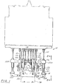
- a welding head assembly in accordance with the invention is generally shown at 10 with associated parts of the overall welding apparatus shown in phantom.
- the overall welding apparatus comprises a main frame, a work zone having loading, welding and unloading stations, means for moving containers to be welded successively from the loading station to the welding station and from the welding station to the unloading station, drive means for operating the apparatus and contact means for activating the drive means in a predetermined sequence.
- the welding station includes the welding head assembly 10 for positioning and controlling the relationship between a battery cover 98 and a battery jar 100 during heating of opposed surfaces thereof and for bringing the heated surfaces together to form a welded joint therebetween as described in more detail later.
- the improved welding head assembly 10 of the present invention has four heating, clamping and bead pressing assemblies which are designated as A, B, C and D respectively. As shown, the assemblies are positioned in opposing pairs, i.e. A and B, C and D.
- Assemblies C and D are short and have a length comparable to the relatively constant width of battery jars which are in a narrow series of either 15.73 or 15.88 cm (6.19 or 6.25 inches) or a wider series of 21.91 cm (8.625 inches).
- assemblies A and B are longer and are positioned outside of assemblies C and D.
- assemblies A and B should have lengths equal to or greater than the longest length that will be handled and it has been found that a length of 33.02 to 25.56 cm (13 to 14 inches) is sufficient for most purposes.
- Each of the assemblies A, B, C and D is, apart from the length differences, constructed substantially identically.
- pairs of vertical mounting plates 12 and 14, and 13 and 15 are affixed to and extend downwardly from main horizontal mounting plate 16 which is a part of the apparatus disclosed in US Patent No.4352977.
- welding head assembly A is disposed on mounting plate 12
- welding head assembly B is disposed on mounting plate 14
- welding head assembly C is disposed on mounting plate 13
- welding head assembly D is disposed on mounting plate 15 (not shown in Figure 1).
- discussion will be limited to the mounting of welding head assembly B to mounting plate 14.
- the welding head assembly B comprises a heating assembly 18 and a clamping and bead pressing assembly 20 which are disposed on and depend from a pair of brackets 22 and 24 mounted on the mounting plate 14. As shown, each bracket 22 and 24 has a horizontal portion 26 and a vertical portion 28.
- the heating assembly 18 is comprised of an L-shaped crank 30 disposed on shaft 32 which is held between brackets 22 and 24. As shown, the crank 30 has a horizontal member 31 and a vertical member 33.
- a pair of bored guides 35 and 37 are vertically disposed on either side of the member 33.
- Shafts 39 and 41 are slidably disposed in guides 35 and 37.
- a bracket 34 is affixed to the ends of shafts 39 and 41 and is movable therewith.
- the bracket 34 supports a heater sub-assembly 38, which comprises a mounting bracket 43, an outer housing 40 affixed thereto, a heater block 42 containing a heater element 45 therein disposed in the outer housing 40 and held therein by bolts 44 and a heater blade 46 attached to the lower portion of the heater block 42 by screws 48.
- the heater sub-assembly 38 is releasably attached to bracket 34 by bolts 36.
- the heating assembly 18 is disposed on the apparatus for substantially horizontal movement and for vertical movement.
- the horizontal movement is provided by the pivoting motion of the crank 30 on shaft 32 created by vertical movement of shaft 54 of a pneumatic or hydraulic cylinder (not shown) via clevis 56 and pin 58 which are attached to the outer end of arm 31.
- Substantially vertical movement of the shaft 54 causes the crank 30 to pivot about shaft 32 thus moving the heater blade 46 into or out of a position where it may be brought into heating contact with a battery jar and battery cover.
- the clamping and bead pressing assembly 20 is located outwardly of and beneath the heating assembly 18 and is supported in this position by vertical portions 28 of brackets 22 and 24 respectively.
- the portions 28 are bored to slidably receive shafts 64 and 66 respectively which are attached to their upper ends (not shown) to the ends of rods 60 and 62 of pneumatic or hydraulic cylinders (not shown).
- a manifold 72 is attached to the lower ends of shafts 64 and 66 by release pins 74.
- the manifold 72 is provided with internal passageways 76 for receiving air or hydraulic fluid from a feed port 78.
- the manifold 72 is also provided with a plurality of piston cavities 80 which slidably receive pistons 82 therein.
- the pistons 82 are provided with biasing means such as spring 84 which urges the piston inwardly of said manifold 72.
- biasing means such as spring 84 which urges the piston inwardly of said manifold 72.
- a collar 86, disposed on the inward face 88 of the manifold 72 prevents the pistons 82 from coming out of the piston cavities 80.
- a presser foot 90 is affixed to the outer end of each piston 82 by screws 91.
- the presser foot 90 has a heater 92 disposed therein and may be provided with a specialised contact plate 94 presenting a non-stick surface for contact with the plastic battery container during welding.
- the heater 92 is used to heat the foot 90 (or the plate 94) to aid in the forming of the welded joint and the contact surface (or the plate 94) may be Teflon (Registered Trade Mark) or the like.
- Bumpers 96 are disposed on each of the pistons 82 for reducing the shock which may be caused by the inward movement of the pistons 82 in response to return by springs 84.
- the individual presser feet 90 are arranged in the same horizontal plane in two opposing pairs 90A,90B and 90C,90D with each presser foot 90 in each pair 90A,90B and 90C,90D being positioned parallel to one another and with the pairs 90A,90B and 90C,90D being perpendicular to one another. such that the opposed pair 90C,90D lie within the area defined between the other opposed pair 90A,90B.
- battery jar 98 with battery elements (not shown) and terminal posts (not shown) in position in the jar 98 and cover 100 thereon is positioned under the welding head assembly 10 as described in US Patent No.4352977.
- the cover 100 is raised with the welding head assembly 10 and the heating assembly 18 is pivoted into position so that the welding/heating blade 46 is disposed between the bottom of the cover 100 and the top of the jar 98 as a result of shaft 54, Figure 2, being urged downwardly by the action of a hydraulic or pneumatic cylinder (not shown).
- the heating assembly is raised by the action of rods 52 and 53 being retracted so that the heating blade 46 comes into melting contact with the cover 100.
- the welding head assembly is then moved downward to a point wherein the heating blade 46 also comes into melting contact with the top of the jar 98.
- the welding head assembly with the cover 100 is moved upward and the heating blade assembly is moved downward thus taking the heating blade out of contact with the cover 100 and the jar 98.
- the heating assembly is then pivoted away from the jar and cover.
- the welding head assembly is moved downwardly to a point where the cover 100 and the jar 98 are almost touching.
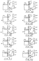
- the presser foot 90B releases from the clamping contact with the jar 98, as shown in Figure 4G, and the assembly 20 is raised to a point where the presser foot 90B is positioned opposite the interface between the cover 100 and the jar 98, as shown in Figure 4H.
- the presser foot 90B is then moved inwardly to contact the jar 98 and the cover 100 and thereby flattens the bead created by the heater blade 46 at the interface of the cover 100 and the jar 98.
- Figure 4J it will be seen that the cover 100 is then slowly lowered and clamped into full contact with the jar 98 causing the two to be welded together.
- the heater 92 is used to heat the presser foot 90B to aid in the forming of the welded joint and the molten plastics material at the interface of the cover 100 and jar 98 is prevented from sticking to the presser foot 90B by the non-stick surface provided by the contact plate 94.
- battery cells made by the apparatus and method of the present invention are less likely to develop leaks at the jar/cover welded interface than are battery cells made by apparatus and methods of prior art.
- thousands of battery cells made by the apparatus and method disclosed in US Patent No.4352977 were tested for leaks over an eight-day period and exhibited an average leak rate of 0.52%.
- battery cells produced by the apparatus and method of the present invention were also tested for leaks and exhibited an average leak rate of 0.31%. In other words, the leak rate was cut almost in half.
- the number and arrangement of the pressure feet may be varied as desired.
- any other suitable means may be provided for applying pressure to the interface between the cover and jar to flatten the molten bead created at the interface during the welding process.
- relative movement between the cover and jar during the welding process is provided by pick-up means of the weld head assembly for raising and lowering the cover with the jar stationary. It will be understood however that such relative movement could be provided either by raising and lowering the jar with the cover stationary or by moving both the cover and jar.
- guide means is preferably provided for maintaining alignment between the relatively movable cover and jar during the welding process.
- the cover may be provided with an integral guide structure such as spaced apart guide posts received in and engageable with the sidewall of the jar to maintain the alignment between the opposed surfaces of the cover and jar during relative movement thereof. It will be understood however that such alignment may be provided by any other suitable means whether part of the cover and/or jar or not.
Landscapes
- Engineering & Computer Science (AREA)
- Mechanical Engineering (AREA)
- Physics & Mathematics (AREA)
- General Chemical & Material Sciences (AREA)
- Chemical & Material Sciences (AREA)
- Electrochemistry (AREA)
- Chemical Kinetics & Catalysis (AREA)
- Fluid Mechanics (AREA)
- Thermal Sciences (AREA)
- Sealing Battery Cases Or Jackets (AREA)
- Primary Cells (AREA)
- Resistance Welding (AREA)
- Connection Of Batteries Or Terminals (AREA)
- Lining Or Joining Of Plastics Or The Like (AREA)
Applications Claiming Priority (2)
| Application Number | Priority Date | Filing Date | Title |
|---|---|---|---|
| US08/012,873 US5296075A (en) | 1993-02-03 | 1993-02-03 | Welding apparatus |
| US12873 | 1993-02-03 |
Publications (2)
| Publication Number | Publication Date |
|---|---|
| EP0611079A1 true EP0611079A1 (fr) | 1994-08-17 |
| EP0611079B1 EP0611079B1 (fr) | 1997-05-21 |
Family
ID=21757148
Family Applications (1)
| Application Number | Title | Priority Date | Filing Date |
|---|---|---|---|
| EP94300703A Expired - Lifetime EP0611079B1 (fr) | 1993-02-03 | 1994-01-31 | Dispositif et procédé de soudage de batterie |
Country Status (5)
| Country | Link |
|---|---|
| US (2) | US5296075A (fr) |
| EP (1) | EP0611079B1 (fr) |
| AT (1) | ATE153275T1 (fr) |
| DE (1) | DE69403233T2 (fr) |
| ES (1) | ES2104268T3 (fr) |
Families Citing this family (14)
| Publication number | Priority date | Publication date | Assignee | Title |
|---|---|---|---|---|
| DE19521476C2 (de) * | 1995-06-13 | 1999-05-27 | Focke & Co | Vorrichtung zum thermischen Siegeln oder Schweißen von Kunststoffolien |
| JP2001511750A (ja) * | 1997-02-20 | 2001-08-14 | エロパック ジステムズ アクチエンゲゼルシャフト | 物品を容器に取付ける装置及び方法 |
| BE1012078A4 (fr) * | 1998-07-22 | 2000-04-04 | Solvay | Machine de soudage d'objets creux et procede pour souder ces objets. |
| USD462938S1 (en) | 2000-03-31 | 2002-09-17 | David M. Revak | Jar for industrial battery |
| US6447948B1 (en) | 2000-03-31 | 2002-09-10 | Accuma Corporation | Jar for industrial electric storage battery |
| KR20010067930A (ko) * | 2001-04-07 | 2001-07-13 | 김종선 | 배터리팩의 접착장치 |
| US7451872B1 (en) * | 2006-07-27 | 2008-11-18 | Boyt Harness Company, Llc | Weaponry container having a rigid outer surface |
| USD559544S1 (en) | 2006-07-27 | 2008-01-15 | Boyt Harness Company, L.L.C. | Container |
| USD559545S1 (en) | 2006-07-27 | 2008-01-15 | Boyt Harness Company, L.L.C. | Container |
| CN100427248C (zh) * | 2006-09-28 | 2008-10-22 | 哈尔滨工业大学 | 采用双向预置应力控制薄板焊接变形和裂纹的夹具 |
| CN100445079C (zh) * | 2007-02-05 | 2008-12-24 | 山东丽鹏股份有限公司 | 一种半自动转盘式塑料盖焊接装置 |
| DE102014221139A1 (de) * | 2014-10-17 | 2016-04-21 | Branson Ultraschall Niederlassung Der Emerson Technologies Gmbh & Co. Ohg | Kunststoff-Vorwärmanordnung für eine Kunststoffschweißvorrichtung, Kunststoffschweißvorrichtung sowie Vorwärmverfahren für ein Bauteil |
| GB201505631D0 (en) * | 2015-04-01 | 2015-05-13 | Rolls Royce Plc | Friction welding vibration damping |
| DE102019117950B4 (de) * | 2019-07-03 | 2023-03-09 | HELLA GmbH & Co. KGaA | Werkzeug, Vorrichtung und Verfahren zum Verschweißen einer Lichtscheibe mit einem Gehäuse einer Automobilleuchte |
Citations (4)
| Publication number | Priority date | Publication date | Assignee | Title |
|---|---|---|---|---|
| JPS5736772A (en) * | 1980-08-12 | 1982-02-27 | Shin Kobe Electric Mach Co Ltd | Manufacture of lead acid battery |
| EP0144569A2 (fr) * | 1979-10-22 | 1985-06-19 | Hardigg Industries, Incorporated | Machine pour souder les bacs d'acculmulateurs |
| EP0313731A1 (fr) * | 1987-09-23 | 1989-05-03 | Georg Fischer Aktiengesellschaft | Procédé et dispositif pour souder des pièces tubulaires en matériau thermoplastique |
| EP0415068A2 (fr) * | 1989-08-31 | 1991-03-06 | Georg Fischer Aktiengesellschaft | Procédé et appareil pour le soudage d'éléments tubulaires en matière thermoplastique |
Family Cites Families (7)
| Publication number | Priority date | Publication date | Assignee | Title |
|---|---|---|---|---|
| US3883369A (en) * | 1973-12-26 | 1975-05-13 | Eltra Corp | Battery assembly machine |
| US4390384A (en) * | 1977-12-20 | 1983-06-28 | Hardigg Industries, Inc. | Method and apparatus for bonding thermoplastic materials |
| US4352977A (en) * | 1980-02-08 | 1982-10-05 | Hardigg Industries, Inc. | Welding apparatus and method |
| US4601768A (en) * | 1984-05-11 | 1986-07-22 | Hydroacoustics, Inc. | Method and apparatus for treating plastic welds to relieve stresses therein |
| US5151149A (en) * | 1988-07-28 | 1992-09-29 | The Entwistle Corporation | Apparatus for bonding or melt fusing plastic and plastic matrix composite materials |
| US5035045A (en) * | 1990-09-10 | 1991-07-30 | Globe-Union Inc. | Method of joining bipolar battery frames |
| US5197994A (en) * | 1990-11-26 | 1993-03-30 | Daniell Battery Manufacturing Co., Inc. | Method of heat sealing a battery |
-
1993
- 1993-02-03 US US08/012,873 patent/US5296075A/en not_active Expired - Lifetime
-
1994
- 1994-01-31 DE DE69403233T patent/DE69403233T2/de not_active Expired - Fee Related
- 1994-01-31 EP EP94300703A patent/EP0611079B1/fr not_active Expired - Lifetime
- 1994-01-31 ES ES94300703T patent/ES2104268T3/es not_active Expired - Lifetime
- 1994-01-31 AT AT94300703T patent/ATE153275T1/de active
- 1994-11-14 US US08/337,967 patent/US5466316A/en not_active Expired - Lifetime
Patent Citations (4)
| Publication number | Priority date | Publication date | Assignee | Title |
|---|---|---|---|---|
| EP0144569A2 (fr) * | 1979-10-22 | 1985-06-19 | Hardigg Industries, Incorporated | Machine pour souder les bacs d'acculmulateurs |
| JPS5736772A (en) * | 1980-08-12 | 1982-02-27 | Shin Kobe Electric Mach Co Ltd | Manufacture of lead acid battery |
| EP0313731A1 (fr) * | 1987-09-23 | 1989-05-03 | Georg Fischer Aktiengesellschaft | Procédé et dispositif pour souder des pièces tubulaires en matériau thermoplastique |
| EP0415068A2 (fr) * | 1989-08-31 | 1991-03-06 | Georg Fischer Aktiengesellschaft | Procédé et appareil pour le soudage d'éléments tubulaires en matière thermoplastique |
Non-Patent Citations (1)
| Title |
|---|
| PATENT ABSTRACTS OF JAPAN vol. 6, no. 107 (E - 113)<985> * |
Also Published As
| Publication number | Publication date |
|---|---|
| ATE153275T1 (de) | 1997-06-15 |
| EP0611079B1 (fr) | 1997-05-21 |
| US5296075A (en) | 1994-03-22 |
| ES2104268T3 (es) | 1997-10-01 |
| HK1002028A1 (en) | 1998-07-24 |
| DE69403233D1 (de) | 1997-06-26 |
| DE69403233T2 (de) | 1997-10-09 |
| US5466316A (en) | 1995-11-14 |
Similar Documents
| Publication | Publication Date | Title |
|---|---|---|
| EP0611079B1 (fr) | Dispositif et procédé de soudage de batterie | |
| CA1260819A (fr) | Methode et dispositif de thermoscellement d'une bande dans une machine de cerclage | |
| CN106450418B (zh) | 一种动力电池全自动封装机 | |
| CN108145987B (zh) | 一种自动盖帽热合机 | |
| EP0559291A1 (fr) | Dispositif pour sceller des récipients | |
| EP0028116A2 (fr) | Couvercle pour bac de batterie | |
| CN117733383A (zh) | 一种焊接测试装置结构 | |
| CN117969276B (zh) | 自动化测试环氧模塑料样块粘度和拉伸强度的装置及方法 | |
| CN217622289U (zh) | 橡胶密封条对接焊机 | |
| HK1002028B (en) | Improved battery welding apparatus and method | |
| CN216326461U (zh) | 一种全自动pvc电路板焊线生产线 | |
| CN215846848U (zh) | 一种自动焊接冲裁整平机 | |
| CN215238569U (zh) | 一种电池外壳焊接装置 | |
| JPH071393A (ja) | 帯状部材の切断方法及び装置 | |
| CN219381660U (zh) | 滤芯筒段热熔机 | |
| US4346874A (en) | Vacuum actuated holding apparatus for a plastic welding machine | |
| CN218193626U (zh) | 可自动除废的端子料带组装压入折料装置 | |
| CN219703399U (zh) | 一种蜡模组树装置 | |
| CN113770739A (zh) | 一种全自动pvc电路板焊线生产线 | |
| US6099777A (en) | Method for cutting openings in a sheet of containers | |
| CN220010311U (zh) | 一种防粘袋的封边机热封边装置 | |
| CN222243710U (zh) | 串焊机焊带夹取设备 | |
| CN220312089U (zh) | 一种高效连续模内激光焊接装置 | |
| CN217169819U (zh) | 一种热熔机构和热熔设备 | |
| CN116072950B (zh) | 一种包Mylar一体机 |
Legal Events
| Date | Code | Title | Description |
|---|---|---|---|
| PUAI | Public reference made under article 153(3) epc to a published international application that has entered the european phase |
Free format text: ORIGINAL CODE: 0009012 |
|
| AK | Designated contracting states |
Kind code of ref document: A1 Designated state(s): AT BE CH DE DK ES FR GB GR IE IT LI LU MC NL PT SE |
|
| 17P | Request for examination filed |
Effective date: 19940927 |
|
| 17Q | First examination report despatched |
Effective date: 19951107 |
|
| GRAG | Despatch of communication of intention to grant |
Free format text: ORIGINAL CODE: EPIDOS AGRA |
|
| GRAH | Despatch of communication of intention to grant a patent |
Free format text: ORIGINAL CODE: EPIDOS IGRA |
|
| GRAH | Despatch of communication of intention to grant a patent |
Free format text: ORIGINAL CODE: EPIDOS IGRA |
|
| GRAA | (expected) grant |
Free format text: ORIGINAL CODE: 0009210 |
|
| AK | Designated contracting states |
Kind code of ref document: B1 Designated state(s): AT BE CH DE DK ES FR GB GR IE IT LI LU MC NL PT SE |
|
| PG25 | Lapsed in a contracting state [announced via postgrant information from national office to epo] |
Ref country code: NL Free format text: LAPSE BECAUSE OF FAILURE TO SUBMIT A TRANSLATION OF THE DESCRIPTION OR TO PAY THE FEE WITHIN THE PRESCRIBED TIME-LIMIT Effective date: 19970521 Ref country code: LI Effective date: 19970521 Ref country code: GR Free format text: LAPSE BECAUSE OF FAILURE TO SUBMIT A TRANSLATION OF THE DESCRIPTION OR TO PAY THE FEE WITHIN THE PRESCRIBED TIME-LIMIT Effective date: 19970521 Ref country code: DK Effective date: 19970521 Ref country code: CH Effective date: 19970521 Ref country code: BE Effective date: 19970521 Ref country code: AT Effective date: 19970521 |
|
| REF | Corresponds to: |
Ref document number: 153275 Country of ref document: AT Date of ref document: 19970615 Kind code of ref document: T |
|
| REG | Reference to a national code |
Ref country code: CH Ref legal event code: EP |
|
| REF | Corresponds to: |
Ref document number: 69403233 Country of ref document: DE Date of ref document: 19970626 |
|
| PG25 | Lapsed in a contracting state [announced via postgrant information from national office to epo] |
Ref country code: SE Effective date: 19970821 Ref country code: PT Effective date: 19970821 |
|
| ET | Fr: translation filed | ||
| REG | Reference to a national code |
Ref country code: ES Ref legal event code: FG2A Ref document number: 2104268 Country of ref document: ES Kind code of ref document: T3 |
|
| NLV1 | Nl: lapsed or annulled due to failure to fulfill the requirements of art. 29p and 29m of the patents act | ||
| REG | Reference to a national code |
Ref country code: CH Ref legal event code: PL |
|
| PG25 | Lapsed in a contracting state [announced via postgrant information from national office to epo] |
Ref country code: LU Free format text: LAPSE BECAUSE OF NON-PAYMENT OF DUE FEES Effective date: 19980131 Ref country code: IE Free format text: LAPSE BECAUSE OF NON-PAYMENT OF DUE FEES Effective date: 19980131 |
|
| PLBE | No opposition filed within time limit |
Free format text: ORIGINAL CODE: 0009261 |
|
| STAA | Information on the status of an ep patent application or granted ep patent |
Free format text: STATUS: NO OPPOSITION FILED WITHIN TIME LIMIT |
|
| 26N | No opposition filed | ||
| PG25 | Lapsed in a contracting state [announced via postgrant information from national office to epo] |
Ref country code: MC Free format text: LAPSE BECAUSE OF NON-PAYMENT OF DUE FEES Effective date: 19980731 |
|
| REG | Reference to a national code |
Ref country code: GB Ref legal event code: IF02 |
|
| PGFP | Annual fee paid to national office [announced via postgrant information from national office to epo] |
Ref country code: ES Payment date: 20090122 Year of fee payment: 16 |
|
| PGFP | Annual fee paid to national office [announced via postgrant information from national office to epo] |
Ref country code: DE Payment date: 20090122 Year of fee payment: 16 |
|
| PGFP | Annual fee paid to national office [announced via postgrant information from national office to epo] |
Ref country code: GB Payment date: 20090122 Year of fee payment: 16 |
|
| PGFP | Annual fee paid to national office [announced via postgrant information from national office to epo] |
Ref country code: IT Payment date: 20090126 Year of fee payment: 16 |
|
| PGFP | Annual fee paid to national office [announced via postgrant information from national office to epo] |
Ref country code: FR Payment date: 20090115 Year of fee payment: 16 |
|
| GBPC | Gb: european patent ceased through non-payment of renewal fee |
Effective date: 20100131 |
|
| REG | Reference to a national code |
Ref country code: FR Ref legal event code: ST Effective date: 20100930 |
|
| PG25 | Lapsed in a contracting state [announced via postgrant information from national office to epo] |
Ref country code: FR Free format text: LAPSE BECAUSE OF NON-PAYMENT OF DUE FEES Effective date: 20100201 |
|
| PG25 | Lapsed in a contracting state [announced via postgrant information from national office to epo] |
Ref country code: DE Free format text: LAPSE BECAUSE OF NON-PAYMENT OF DUE FEES Effective date: 20100803 |
|
| PG25 | Lapsed in a contracting state [announced via postgrant information from national office to epo] |
Ref country code: GB Free format text: LAPSE BECAUSE OF NON-PAYMENT OF DUE FEES Effective date: 20100131 |
|
| REG | Reference to a national code |
Ref country code: ES Ref legal event code: FD2A Effective date: 20110328 |
|
| PG25 | Lapsed in a contracting state [announced via postgrant information from national office to epo] |
Ref country code: IT Free format text: LAPSE BECAUSE OF NON-PAYMENT OF DUE FEES Effective date: 20100131 |
|
| PG25 | Lapsed in a contracting state [announced via postgrant information from national office to epo] |
Ref country code: ES Free format text: LAPSE BECAUSE OF NON-PAYMENT OF DUE FEES Effective date: 20110315 |
|
| PG25 | Lapsed in a contracting state [announced via postgrant information from national office to epo] |
Ref country code: ES Free format text: LAPSE BECAUSE OF NON-PAYMENT OF DUE FEES Effective date: 20100201 |