EP0611241A1 - Dispositif de stabilisation et de renforcement pour cric de voiture - Google Patents
Dispositif de stabilisation et de renforcement pour cric de voiture Download PDFInfo
- Publication number
- EP0611241A1 EP0611241A1 EP94500019A EP94500019A EP0611241A1 EP 0611241 A1 EP0611241 A1 EP 0611241A1 EP 94500019 A EP94500019 A EP 94500019A EP 94500019 A EP94500019 A EP 94500019A EP 0611241 A1 EP0611241 A1 EP 0611241A1
- Authority
- EP
- European Patent Office
- Prior art keywords
- stirrup
- arm
- foot
- vehicle
- central
- Prior art date
- Legal status (The legal status is an assumption and is not a legal conclusion. Google has not performed a legal analysis and makes no representation as to the accuracy of the status listed.)
- Granted
Links
- 230000003014 reinforcing effect Effects 0.000 title claims abstract description 9
- 230000000087 stabilizing effect Effects 0.000 title claims abstract description 9
- 210000002683 foot Anatomy 0.000 claims description 19
- 210000004744 fore-foot Anatomy 0.000 claims description 2
- 230000002787 reinforcement Effects 0.000 description 5
- 230000000284 resting effect Effects 0.000 description 3
- 239000000725 suspension Substances 0.000 description 3
- 238000003466 welding Methods 0.000 description 3
- 230000009471 action Effects 0.000 description 2
- 238000005452 bending Methods 0.000 description 2
- 239000000463 material Substances 0.000 description 2
- 230000015572 biosynthetic process Effects 0.000 description 1
- 230000008859 change Effects 0.000 description 1
- 230000007547 defect Effects 0.000 description 1
- 230000006866 deterioration Effects 0.000 description 1
- 230000000694 effects Effects 0.000 description 1
- 238000003780 insertion Methods 0.000 description 1
- 230000037431 insertion Effects 0.000 description 1
- 230000007246 mechanism Effects 0.000 description 1
- 230000004048 modification Effects 0.000 description 1
- 238000012986 modification Methods 0.000 description 1
- 230000002035 prolonged effect Effects 0.000 description 1
- 230000004044 response Effects 0.000 description 1
- 238000000926 separation method Methods 0.000 description 1
- 239000013589 supplement Substances 0.000 description 1
Images

Classifications
-
- B—PERFORMING OPERATIONS; TRANSPORTING
- B66—HOISTING; LIFTING; HAULING
- B66F—HOISTING, LIFTING, HAULING OR PUSHING, NOT OTHERWISE PROVIDED FOR, e.g. DEVICES WHICH APPLY A LIFTING OR PUSHING FORCE DIRECTLY TO THE SURFACE OF A LOAD
- B66F3/00—Devices, e.g. jacks, adapted for uninterrupted lifting of loads
- B66F3/08—Devices, e.g. jacks, adapted for uninterrupted lifting of loads screw operated
- B66F3/12—Devices, e.g. jacks, adapted for uninterrupted lifting of loads screw operated comprising toggle levers
Definitions
- the present Utility Model relates to a stabilizing and reinforcing device for vehicle-raising jacks, which device is applicable to mechanical vehicle-raising jacks of various types, such as "Y"-form jacks, parallelogram jacks, parallelogram jacks with downwardly extending leg, and others.
- the different types of known jacks provide various advantages which make them especially useful for specific differentiated applications of the jacks, in accordance with the technical requirements of the manufacturers of the corresponding vehicles.
- the problem raised in general by vehicle-raising jacks in respect of utilization thereof by a normal user without specific knowledge in this field and sometimes not even conversant with correct utilization of a jack to change a damaged wheel on his/her vehicle, consists in ensuring the stability of the whole formed by the jack and the vehicle during the functional operation of the former and also in resisting the mechanical stress required by the vehicle manufacturer and contemplated, amongst other technical specifications, in their corresponding conditions.
- mechanical jacks for raising vehicles present a support for holding the corresponding lower part of the vehicle to be raised, which support is also denominated stirrup and is in some cases fixed, that is, it is firmly attached to the end of the carrying arm, while in other cases it can rotate with respect to a transversal horizontal axis of the end of said carrying arm, so that it constitutes an axis of rotation for the stirrup, so that the latter can fit better against the bodywork of the vehicle during raising and lowering with the corresponding mechanical jack.
- the known stirrups present a U- or V-shaped recess or channel, in which channel can be freely housed a lower flange on the corresponding lower part of the vehicle bodywork, reinforced in that zone in order to withstand the mechanical stresses of the jack stirrup support for raising the vehicle.
- the said flange serves to guide the jack stirrup and prevent any accidental slippage, without the flange resting in the bottom of the stirrup channel.
- Utility Model no. 247.051 discloses a vehicle-raising jack of the "Y" type, like type a) described above, and characterized essentially in that the rotation shaft of the support plate or stirrup rests directly on the lower side of same and is set approximately in a horizontal plane with the formation projecting from the underside of the vehicle, that is, from the lower part of the vehicle bodywork in which said jack support plate or stirrup is placed and fitted.
- a jack provided with a stirrup articulated to the end of its carrying arm, through a rotation shaft parallel to the tilting axis, can adapt better to the relative movement between the vehicle bodywork and said jack than is the case of a jack with a stirrup which is fixed with respect to its carrying arm.
- the invention embodies a solution to the problems described above, for the purposes of which the object of this Utility Model is a stabilizing and reinforcing device for vehicle-raising jacks, which comprises an arm provided at one end with a stirrup as resting point and support for the vehicle and which has the form of a transversal channel with at least one flat front support portion, an arm or column to which the foot of the jack is articulated and a nut into which the jack worm is threaded; characterized in that the stirrup is provided, at the front support portion thereof, with three downwardly directed projections, one of them central and the other two equidistant therefrom, aligned transversally and situated near the channel and at a distance from the respective side edges of said front portion of the stirrup, which projections rest against a transversal rod slightly longer than the gap between the two equidistant projections and fixed at the end of the stirrup carrying arm,
- the said stabilizing and reinforcing device can be applied to any of the known types of jacks or to any other future type having the parts or means defined above before the work "characterized".
- the stabilizing and reinforcing device for vehicle-raising jacks presents, amongst others, the following advantages: increased jack stability, reinforcement of mechanically critical parts of the jack and increased user ease of initial jack placement position underneath the bodywork of the vehicle to which it is applied.
- the device according to the present Utility Model offers the advantages described above, in addition to others which can be deduced easily from the example of embodiment of said device, which is described in greater detail below in order to facilitate an understanding of the characteristics outlined above, at the same time providing information about various details, the specification being accompanied by drawings which, only by way of example and without limitation of the scope of the present invention, show a practical embodiment of the said stabilizing and reinforcing device for vehicle-raising jacks.
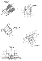
- figure 1 shows a side elevation view of the jack, starting to rise underneath the vehicle bodywork (of which a part is shown schematically);
- figure 2 is a cross section view along the line II-II of figure 1, and shows a detail of assembly of the nut;
- figure 3 is a view in accordance with arrow A of figure 1;
- figure 4 is a cross section view along the line IV-IV of figure 1, showing the articulation between the stirrup carrying arm and the column;
- figure 5 is a cross section view along the line V-V of figure 1, and shows the stirrup;
- figure 6 is a cross section view along the line VI-VI of figure 1, showing the lower part of the jack at the ground support zone thereof.
- a jack of the "Y" type comprising a column 1 (which in the case of the parallelogram-type jack would be an arm) to which is articulated a foot 2 for support of the jack on the ground, to which column is in turn articulated at an intermediate point thereof a raising arm 3 (carrying a stirrup), which articulation is implemented through the corresponding shaft 4 in such a way that the raising arm presents at this articulation two cylindrical recesses 5 (figure 4), which reinforce this part of the arm and provide a large support surface for it at its articulation with the column 1.
- the column 1 and the raising arm 3 are linked by a worm 6 which traverses and is threaded in a nut 7 (figures 1 and 2), which is this case is made of plastic material, which is provided with two transversal and opposite trunnions 8 which are inserted in the two cylindrical recesses 9 on the column 1 for tilting of the nut and, in consequence, of the worm 6, which cylindrical recesses form a reinforcement for this part of the column and a larger support surface for the nut.
- a worm 6 which traverses and is threaded in a nut 7 (figures 1 and 2), which is this case is made of plastic material, which is provided with two transversal and opposite trunnions 8 which are inserted in the two cylindrical recesses 9 on the column 1 for tilting of the nut and, in consequence, of the worm 6, which cylindrical recesses form a reinforcement for this part of the column and a larger support surface for the nut.
- a pin 10 which secures and retains the two vertical wings of the U-profile of the column, which avoids any separation of said wings in the zone of the nut, and therefore avoids any escape of the trunnions 8 of said nut.
- the worm 6 is borne at its front end by a support which can consist of a bearing 11, as shown in figure 1, or of other suitable means for retaining the front end of the worm in position, while at the same time facilitating its rotation with respect to its transversal support, which in this example consists of a sort of transversal shaft 12 articulated to the two vertical and parallel wings of the raising arm 3 and against which the bearing 11 rests, while on the opposite part there is a sleeve 13 fixed on the worm 6, which retains the arm 3 with respect to the front end of the worm, while at the same time forming a stop for maximum raising of the arm 3 with respect to the column 1.
- a support which can consist of a bearing 11, as shown in figure 1, or of other suitable means for retaining the front end of the worm in position, while at the same time facilitating its rotation with respect to its transversal support, which in this example consists of a sort of transversal shaft 12 articulated to the two vertical and parallel wings of the raising arm 3 and against which the bearing 11
- crank 14 is linked in articulation a crank 14, as a means for the user to make the nut rotate in order to have it withdraw or advance, that is, to raise or lower the arm 3 with its stirrup and, in consequence, the bodywork of the vehicle to which it is applied.
- the crank 14 is articulated inseparably to the rear end of the worm 6, with stops fitted to establish its operating position, although the rotating action of the worm could be implemented by other means, which could even consist in a separatable or disassemblable connexion between the crank or the like and the rear end of the worm.
- the column 1 is generally "U"-shaped with its free ends bent, in turn, in the form of an inverted-position "U", counterpoising each other, as shown in figure 4.
- the base of this "U” profile is interrupted at the upper end of the column, being partially prolonged and following the oblique cut of that end, in the form of two wings 15 (figure 3) which prevent the two vertical-profile wings on this part of the column coming together, thus preventing them pressing against the nut 7, avoiding the greater effort which this would involve as a result of a certain braking effect on said nut, and also avoiding eventual deterioration thereof due to that action.
- the lower end of the column also presents a similar layout, such that the base of its profile is lengthened, bending according to the oblique cut of said lower end and interposing itself between the two wings of the column, thus preventing them coming together, that is, keeping them in their correct positions.
- the specific profile of the column could clearly be any other with the necessary mechanical strength for its function, including two parallel profiles joined together by cross-members.
- the raising arm 3 is constituted, in this example, by a "U" profile, although it could be any other of suitable mechanical strength, whose free end is cut off obliquely, so that the base of the profile is lengthened, bending and interposing itself between the two vertical wings of the profile, to which it is welded at its end, the wings forming two upward prolongations 16, to the upper part of which is welded a transversal rod 17 (figures 1 and 5).
- the stirrup 18 serves to hold and support the vehicle to which the mechanical jack is applied and adopts the overall configuration of a transversal channel, of "U" shape in this example (although it could have a "V” shape or any other suitable shape), in which channel may be fitted freely the lower flange 19 provided for this purpose on the corresponding lower part of the automobile bodywork; and said stirrup is further provided with at least one front portion 20 at which is implemented properly speaking the support of the vehicle bodywork, that part being substantially flat for this purpose.
- the stirrup On said front support portion 20, the stirrup has three downward projections 21, 22 and 23, projection 21 being central and the other two projections 22 and 23 equidistant there from and situated on either side of it, these three projections being aligned transversally and situated close to the channel of the stirrup and at a certain distance from the respective side edges of the above-mentioned front support portion 20, as can be seen in figure 5; and these projections 21, 22 and 23 rest against the rod 17, which is slightly longer than the gap between the two side projections 22 and 23.
- the stirrup 18 has linked to it, by welding in this example, a plate 24 of narrower width than the internal gap between the two vertical wings of the end of the arm 3 carrying the stirrup 18, so that there exists transversal play which permits the stirrup to move in that direction in relation to its carrying arm 3.
- the projections 21, 22 and 23 can be constituted by recesses (as shown in figure 5) or by pieces or supplements fixed below the stirrup and set between the lower side of its front support portion 20 and the transversal rod, to form its swivelling support on the latter; and, in any case, such lower projections form a stirrup reinforcement at this point of same.
- the lower part of the plate 24 is fixed, in this case by welding, to a front, central flange 25 cut out of the stirrup channel and projecting downwards, extending still further below the plate 24 and having an orifice into which is fixed the end of a central spring 26, whose opposite end is attached to the base of the stirrup-carrying arm 3 profile, so that in the inactive position of the stirrup 18, it keeps the latter centred against the rod and in a predetermined position owing to the location of the lower anchorage point of the spring to said arm.
- the plate 24 is configured as two parallel, opposite parts linked by another intermediate one, forming the configuration of figure 1, similar to the cipher four and forming a lower, central, tubular part situated in front of the front wall of the stirrup 18 channel and underneath its front support portion 20, which tubular part forms a central housing by which said stirrup is articulated freely to the rod 17 with substantial play in several directions, in addition to the transversal travel with respect to the rod 17 described above.
- the spring 26 has the function of centring the stirrup 18, also situating it initially to facilitate automatic positioning by the user when s/he moves in the mechanical jack and places it under the vehicle bodywork, in addition to the function of eliminating the noise which the stirrup would produce when stowed in the corresponding part of the vehicle.
- the foot 2 of the mechanical jack is provided with depression (figures 1 and 6) centred transversally, which mechanically reinforces the foot, while at the same time permitting the articulation shaft 28 between the lower end of the column 1 and the foot 2 to be as low as possible, thus increasing the stability of the jack.
- This shaft 28 is fixed, in this example by welding, on the foot 2, just on top thereof and has a spring 29 coiled around the central part thereof, the ends of which rest resiliently against said lower part of the column 1 and against the foot 2, urging the latter against the lower part of the column when the jack is inactive and raising of the column with respect the support foot on the ground has not commenced, which also predetermines automatically an initial placement position for the user, while at the same time avoiding any noise which the jack might make when stowed in the vehicle.
- the column has two cylindrical recesses 30 which reinforce its two vertical wings at this part of articulation with the foot, forming a larger surface area of support of the column on the shaft 28.
- the lower part of the column 1, which in the initial position of the jack is located within the hollow 27, may have stops 31 for positioning thereof with respect to the bottom of the hollow 27 of the foot 22, while the latter may have pawls 32 for gripping the ground or, in any case, improving the grip of the foot on the ground on which it rests.
Landscapes
- Life Sciences & Earth Sciences (AREA)
- Engineering & Computer Science (AREA)
- Geology (AREA)
- Mechanical Engineering (AREA)
- Structural Engineering (AREA)
- Vehicle Cleaning, Maintenance, Repair, Refitting, And Outriggers (AREA)
- Catching Or Destruction (AREA)
Applications Claiming Priority (2)
| Application Number | Priority Date | Filing Date | Title |
|---|---|---|---|
| ES9300303U ES1023878Y (es) | 1993-02-08 | 1993-02-08 | Dispositivo estabilizador y de refuerzo para gatos elevadores de vehiculos. |
| ES9300303U | 1993-02-08 |
Publications (2)
| Publication Number | Publication Date |
|---|---|
| EP0611241A1 true EP0611241A1 (fr) | 1994-08-17 |
| EP0611241B1 EP0611241B1 (fr) | 1998-05-06 |
Family
ID=8280805
Family Applications (1)
| Application Number | Title | Priority Date | Filing Date |
|---|---|---|---|
| EP19940500019 Expired - Lifetime EP0611241B1 (fr) | 1993-02-08 | 1994-02-07 | Cric de voiture |
Country Status (3)
| Country | Link |
|---|---|
| EP (1) | EP0611241B1 (fr) |
| DE (1) | DE69409993T2 (fr) |
| ES (2) | ES1023878Y (fr) |
Citations (4)
| Publication number | Priority date | Publication date | Assignee | Title |
|---|---|---|---|---|
| DE7414229U (de) * | 1974-07-25 | Allendorfer Fabrik Fuer Stahlverarbeitung Panne H Kg | Wagenheber | |
| DE8706754U1 (de) * | 1987-05-12 | 1987-08-06 | August Bilstein GmbH & Co KG, 5828 Ennepetal | Wagenheber |
| EP0451643A2 (fr) * | 1990-04-10 | 1991-10-16 | Xavier Salvador Rovira | Vérin mécanique amélioré pour des véhicules automobiles |
| EP0469234A1 (fr) * | 1990-07-30 | 1992-02-05 | Tub S.A. | Vérin mécanique perfectionné pour des véhicules automobiles |
-
1993
- 1993-02-08 ES ES9300303U patent/ES1023878Y/es not_active Expired - Fee Related
-
1994
- 1994-02-07 EP EP19940500019 patent/EP0611241B1/fr not_active Expired - Lifetime
- 1994-02-07 ES ES94500019T patent/ES2116564T3/es not_active Expired - Lifetime
- 1994-02-07 DE DE1994609993 patent/DE69409993T2/de not_active Expired - Lifetime
Patent Citations (4)
| Publication number | Priority date | Publication date | Assignee | Title |
|---|---|---|---|---|
| DE7414229U (de) * | 1974-07-25 | Allendorfer Fabrik Fuer Stahlverarbeitung Panne H Kg | Wagenheber | |
| DE8706754U1 (de) * | 1987-05-12 | 1987-08-06 | August Bilstein GmbH & Co KG, 5828 Ennepetal | Wagenheber |
| EP0451643A2 (fr) * | 1990-04-10 | 1991-10-16 | Xavier Salvador Rovira | Vérin mécanique amélioré pour des véhicules automobiles |
| EP0469234A1 (fr) * | 1990-07-30 | 1992-02-05 | Tub S.A. | Vérin mécanique perfectionné pour des véhicules automobiles |
Also Published As
| Publication number | Publication date |
|---|---|
| ES1023878U (es) | 1993-08-01 |
| EP0611241B1 (fr) | 1998-05-06 |
| ES2116564T3 (es) | 1998-07-16 |
| ES1023878Y (es) | 1994-05-01 |
| DE69409993D1 (de) | 1998-06-10 |
| DE69409993T2 (de) | 1998-09-10 |
Similar Documents
| Publication | Publication Date | Title |
|---|---|---|
| US3989225A (en) | Vehicle lifting jack | |
| US4984657A (en) | Service lift stand apparatus for small tractors | |
| US5271603A (en) | Vehicle jack | |
| EP0151154B1 (fr) | Cercle horizontal | |
| US6070856A (en) | Car jack | |
| CA1263373A (fr) | Verin de vehicule | |
| EP0622329B1 (fr) | Cric de véhicules | |
| JPS63503302A (ja) | 自動車用リフト | |
| CS348491A3 (en) | Car jack | |
| EP0611241B1 (fr) | Cric de voiture | |
| CA1164850A (fr) | Dispositif de levage par la partie laterale de voitures monocoque | |
| JP3731649B2 (ja) | 車両の試験用補助装置 | |
| EP0774440B1 (fr) | Elément supportant unitaire | |
| CN217515207U (zh) | 一种焊接小车支腿快速升降机构 | |
| EP0396233A1 (fr) | Cric de véhicule | |
| EP0516314B1 (fr) | Crics pour véhicule | |
| US5782456A (en) | Vehicle jack | |
| US4720081A (en) | Screw drive six link side lift vehicle jack assembly | |
| CN111776087B (zh) | 一种带有安全限位装置的工件翻转系统及矿用自卸车 | |
| US4893785A (en) | Lifting device | |
| US20030001145A1 (en) | Jack | |
| CN212712640U (zh) | 一种用于工件翻转系统的安全限位装置 | |
| MXPA01012964A (es) | Gato. | |
| EP0383542A1 (fr) | Cric pour lever une charge | |
| CN224209911U (zh) | 一种接点架安装用的工装 |
Legal Events
| Date | Code | Title | Description |
|---|---|---|---|
| PUAI | Public reference made under article 153(3) epc to a published international application that has entered the european phase |
Free format text: ORIGINAL CODE: 0009012 |
|
| AK | Designated contracting states |
Kind code of ref document: A1 Designated state(s): BE DE ES FR GB IT PT |
|
| 17P | Request for examination filed |
Effective date: 19950110 |
|
| 17Q | First examination report despatched |
Effective date: 19961029 |
|
| GRAG | Despatch of communication of intention to grant |
Free format text: ORIGINAL CODE: EPIDOS AGRA |
|
| GRAG | Despatch of communication of intention to grant |
Free format text: ORIGINAL CODE: EPIDOS AGRA |
|
| GRAH | Despatch of communication of intention to grant a patent |
Free format text: ORIGINAL CODE: EPIDOS IGRA |
|
| GRAH | Despatch of communication of intention to grant a patent |
Free format text: ORIGINAL CODE: EPIDOS IGRA |
|
| RAP1 | Party data changed (applicant data changed or rights of an application transferred) |
Owner name: TUBSA AUTOMOCION, S.L. |
|
| GRAA | (expected) grant |
Free format text: ORIGINAL CODE: 0009210 |
|
| AK | Designated contracting states |
Kind code of ref document: B1 Designated state(s): BE DE ES FR GB IT PT |
|
| REF | Corresponds to: |
Ref document number: 69409993 Country of ref document: DE Date of ref document: 19980610 |
|
| REG | Reference to a national code |
Ref country code: ES Ref legal event code: FG2A Ref document number: 2116564 Country of ref document: ES Kind code of ref document: T3 |
|
| ITF | It: translation for a ep patent filed | ||
| ET | Fr: translation filed | ||
| REG | Reference to a national code |
Ref country code: PT Ref legal event code: SC4A Free format text: AVAILABILITY OF NATIONAL TRANSLATION Effective date: 19980713 |
|
| PLBE | No opposition filed within time limit |
Free format text: ORIGINAL CODE: 0009261 |
|
| STAA | Information on the status of an ep patent application or granted ep patent |
Free format text: STATUS: NO OPPOSITION FILED WITHIN TIME LIMIT |
|
| 26N | No opposition filed | ||
| REG | Reference to a national code |
Ref country code: GB Ref legal event code: IF02 |
|
| PG25 | Lapsed in a contracting state [announced via postgrant information from national office to epo] |
Ref country code: IT Free format text: LAPSE BECAUSE OF NON-PAYMENT OF DUE FEES Effective date: 20070207 |
|
| PGFP | Annual fee paid to national office [announced via postgrant information from national office to epo] |
Ref country code: PT Payment date: 20100113 Year of fee payment: 17 Ref country code: ES Payment date: 20100218 Year of fee payment: 17 |
|
| PGFP | Annual fee paid to national office [announced via postgrant information from national office to epo] |
Ref country code: FR Payment date: 20100210 Year of fee payment: 17 |
|
| PGFP | Annual fee paid to national office [announced via postgrant information from national office to epo] |
Ref country code: GB Payment date: 20100205 Year of fee payment: 17 Ref country code: DE Payment date: 20100219 Year of fee payment: 17 Ref country code: BE Payment date: 20100222 Year of fee payment: 17 |
|
| PGFP | Annual fee paid to national office [announced via postgrant information from national office to epo] |
Ref country code: IT Payment date: 20100222 Year of fee payment: 17 |
|
| PGRI | Patent reinstated in contracting state [announced from national office to epo] |
Ref country code: IT Effective date: 20110616 |
|
| REG | Reference to a national code |
Ref country code: PT Ref legal event code: MM4A Free format text: LAPSE DUE TO NON-PAYMENT OF FEES Effective date: 20110808 |
|
| BERE | Be: lapsed |
Owner name: *TUBSA AUTOMOCION S.L. Effective date: 20110228 |
|
| GBPC | Gb: european patent ceased through non-payment of renewal fee |
Effective date: 20110207 |
|
| PG25 | Lapsed in a contracting state [announced via postgrant information from national office to epo] |
Ref country code: PT Free format text: LAPSE BECAUSE OF NON-PAYMENT OF DUE FEES Effective date: 20110808 |
|
| REG | Reference to a national code |
Ref country code: FR Ref legal event code: ST Effective date: 20111102 |
|
| PG25 | Lapsed in a contracting state [announced via postgrant information from national office to epo] |
Ref country code: BE Free format text: LAPSE BECAUSE OF NON-PAYMENT OF DUE FEES Effective date: 20110228 |
|
| PGRI | Patent reinstated in contracting state [announced from national office to epo] |
Ref country code: IT Effective date: 20110616 |
|
| REG | Reference to a national code |
Ref country code: DE Ref legal event code: R119 Ref document number: 69409993 Country of ref document: DE Effective date: 20110901 |
|
| PG25 | Lapsed in a contracting state [announced via postgrant information from national office to epo] |
Ref country code: FR Free format text: LAPSE BECAUSE OF NON-PAYMENT OF DUE FEES Effective date: 20110228 |
|
| PG25 | Lapsed in a contracting state [announced via postgrant information from national office to epo] |
Ref country code: GB Free format text: LAPSE BECAUSE OF NON-PAYMENT OF DUE FEES Effective date: 20110207 |
|
| REG | Reference to a national code |
Ref country code: ES Ref legal event code: FD2A Effective date: 20120411 |
|
| PG25 | Lapsed in a contracting state [announced via postgrant information from national office to epo] |
Ref country code: ES Free format text: LAPSE BECAUSE OF NON-PAYMENT OF DUE FEES Effective date: 20110208 |
|
| PG25 | Lapsed in a contracting state [announced via postgrant information from national office to epo] |
Ref country code: DE Free format text: LAPSE BECAUSE OF NON-PAYMENT OF DUE FEES Effective date: 20110901 |