EP0611355B1 - Zweiteiliger kunststoff-clip zum verschliessen von wursthüllen, beuteln o. dgl. - Google Patents
Zweiteiliger kunststoff-clip zum verschliessen von wursthüllen, beuteln o. dgl. Download PDFInfo
- Publication number
- EP0611355B1 EP0611355B1 EP92923429A EP92923429A EP0611355B1 EP 0611355 B1 EP0611355 B1 EP 0611355B1 EP 92923429 A EP92923429 A EP 92923429A EP 92923429 A EP92923429 A EP 92923429A EP 0611355 B1 EP0611355 B1 EP 0611355B1
- Authority
- EP
- European Patent Office
- Prior art keywords
- piece
- frame
- plastic clip
- side members
- pleat
- Prior art date
- Legal status (The legal status is an assumption and is not a legal conclusion. Google has not performed a legal analysis and makes no representation as to the accuracy of the status listed.)
- Expired - Lifetime
Links
Images


Classifications
-
- B—PERFORMING OPERATIONS; TRANSPORTING
- B65—CONVEYING; PACKING; STORING; HANDLING THIN OR FILAMENTARY MATERIAL
- B65D—CONTAINERS FOR STORAGE OR TRANSPORT OF ARTICLES OR MATERIALS, e.g. BAGS, BARRELS, BOTTLES, BOXES, CANS, CARTONS, CRATES, DRUMS, JARS, TANKS, HOPPERS, FORWARDING CONTAINERS; ACCESSORIES, CLOSURES, OR FITTINGS THEREFOR; PACKAGING ELEMENTS; PACKAGES
- B65D33/00—Details of, or accessories for, sacks or bags
- B65D33/16—End- or aperture-closing arrangements or devices
- B65D33/1616—Elements constricting the neck of the bag
-
- Y—GENERAL TAGGING OF NEW TECHNOLOGICAL DEVELOPMENTS; GENERAL TAGGING OF CROSS-SECTIONAL TECHNOLOGIES SPANNING OVER SEVERAL SECTIONS OF THE IPC; TECHNICAL SUBJECTS COVERED BY FORMER USPC CROSS-REFERENCE ART COLLECTIONS [XRACs] AND DIGESTS
- Y10—TECHNICAL SUBJECTS COVERED BY FORMER USPC
- Y10T—TECHNICAL SUBJECTS COVERED BY FORMER US CLASSIFICATION
- Y10T24/00—Buckles, buttons, clasps, etc.
- Y10T24/15—Bag fasteners
Definitions
- the invention relates to a plastic clip for closing sausage casings, pouches or the like made of two parts.
- Such a plastic clip is known for example from DE-B-10 23 693.
- a part consists of a capsule which is circular in plan view and which is provided in the area of opposite sectors of its circumference with correspondingly curved stands on an essentially flat floor.
- the braid of the casing end is inserted between the stands and is clamped in place by a cover which forms the second clip part and which engages behind locking projections on the upper edges of the stands.
- a peg formed on the bottom of the first part presses the braid in a wave-like manner into a corresponding recess on the cover part.
- the invention seeks to solve the problems mentioned above. It consists of a for closing sausage casings, bags or the like.
- certain plastic clip made of two parts, which comprise the end of the sheath gathered into a braid and can be locked together, at least one part of which is designed as an elongated, closed frame running transversely to the length of the braid and made of side webs and crossbars and the other essentially covering the frame Part has at least one projection facing the one part in the form of a rib which, when the clip is in the locked state, runs parallel to the side webs of the frame, projects into the interior thereof and deflects the braid in a wave-like manner and puts pressure under pressure, the side webs being high compared to the wall thickness of the frame on their narrow sides facing the braid between the transverse webs, which are aligned with one another in the longitudinal direction of the braid and which extend rounded over a larger section of the length of the lateral webs and their elasticity in relation to the pressing pressure of the sleeve braid enlarge.
- a clip for attaching flexible, elongated elements such as electrical cables to support elements is known, with the help of which the cables on walls, household appliances or the like. attached and fixed by pressure.
- This clip consists of two parts, which enclose the cable and can be locked together, in the closed state two parallel side webs of one part, which are only connected by a floor, hold the cable in small rectangular recesses, while one that runs parallel to the side webs and in the middle between them on the other part in the form of a rib presses the cable and this fixes by multiple deflection.
- the fastening of cables is not only in a different technical field than the closing of sausage casings, bags or the like, but is also not functionally comparable, because there are different requirements for the self-contained, incompressible cables than with braids and the problems described above cannot arise there.
- the known fastening chip lacks the frame formed according to the invention from side and transverse webs, the side webs of which have rounded depressions which extend over a larger section of the side webs, so that the elasticity of the side webs and thus of the entire clip are changed by deliberately influencing the section modulus can.
- the interior of the frame forms a chamber into which the braid of the casing end is deflected and the volume of which can be changed within certain limits by the elastic deformation of the frame side webs.
- a first form of the inventive concept sees before that both parts are frame-shaped, each with an identical protrusion arranged in the pigtail longitudinal extension between the side webs, and can be locked together with mutually directed depressions. This has the great advantage that, in contrast to what has hitherto been the case, only one clip part (in duplicate) is required, which simplifies both the production costs and the storage and the feeding for attaching the clip.
- the depressions in the side webs are arcuate and the rib is a less deeply recessed intermediate web running parallel to the side webs.
- the overhead connection of the two identical clip parts results in a relative reversal of the sides, which not only allows the latching (with latching cutouts and latching arms offset with respect to the side bars), but also leads to the fact that it is arranged eccentrically with respect to the length of the braid Projection in the form of the intermediate web is opposite the wider chamber part, which is in each case formed by the intermediate web of the other clip part within the frame.
- each clip part has only one projection, the sleeve braid is deflected several times when the clip is closed.
- a first part of the clip has an open frame, the side webs of which have depressions in the form of U-shaped cutouts, and that a second part closes the U-shaped cutouts of the first part, the rib on the second Part is molded.
- the frame side webs in the sense of the 'bulging' described above, due to the arrangement according to the invention of the U-cutouts leading the sleeve braid in the side webs and the pressing of the braid by the rib on the second clip part, there is also a force in the plane the frame side webs, i.e. perpendicular to the bulging forces acting in the axial direction of the braid.
- a further development of the plastic clip according to the invention provides that the side webs of the frame are connected by transverse webs, in which locking cutouts are formed, behind which locking arms formed on the other part engage in the closed state.
- this makes the latching connection independent of the widening of the U-cutouts of the side webs. It is particularly advantageous if the latching arms of the second part — viewed in the direction of the U-cutouts of the side webs — are arranged on both sides (offset in the viewing direction) next to the cutouts of the side webs forming the U openings.
- the (correspondingly wide) frame of the first part is divided by a central web running parallel to the side webs, that the central web has a cutout that is less deep than the cutouts of the side webs and that the second part has two pairs of locking arms, each of which engages in one of the two chambers of the frame.
- two plastic clips of the type described above are arranged next to one another in such a way that their side webs adjoining one another are combined to form that central web, with the further proviso that the central web cutout is less deep than the cutouts of the outer side webs.
- the latter has a stronger deflection of the braid in the one hand Plane of the central web and also leads to a higher section modulus than the side webs with respect to forces perpendicular to the braid axis.
- An additional reinforcement of the deflection and sealing function of the raised central web can be achieved by a slot in the first part, which is arranged in the plane of the central web, and into which the raised central web presses the sleeve braid.
- EP-A-481 235 describes two-part plastic clips consisting of different parts, in which a projection provided on one part presses the sleeve braid into a chamber formed in the other part and this is elastically deformed depending on the braid volume and possibly the pressure built up inside the casing.
- this tendency to deform does not counteract the elastic resistance of a closed frame, because the transverse webs are separated on two opposite sides of the chamber by so-called relief cuts. Therefore, there is no - or at least not primarily - an elastic bulging of the side webs, but a reverse V-shaped gaping apart.
- a framework in the sense of the inventive concept presupposes an all-round closed sequence of walls which are capable of the uninterrupted transmission of tensile and bending forces.
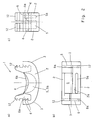
- Fig. 1 shows a perspective view of one half of the first embodiment of the plastic clip according to the invention; the other half is formed by an identical part which - compared to the illustration in FIG. 1 over 180 ° about the longitudinal axis of the braid of a sausage casing (not shown) or the like running from bottom right to top left - is formed from a rotated plastic part. It can be seen that these two identical parts can be locked together due to their relative rotation.
- FIG. 2 (a) Each of these two parts accordingly consists of one of the side webs 2 and the (in contrast thicker) cross webs 3; the dashed arc line in Fig. 2 (a) makes it clear that the frame is closed on the outside.
- the representation of Figures 1 and 2 is greatly enlarged; in practice, the side webs 2 are only 1 mm thick. Between the side webs 2 and parallel to them, an intermediate web 2a is formed off-center (see FIG. 2 (a)), which corresponds to that of the Side bars 2 and cross bars 3 enclosed frame interior divided into two sub-rooms 5 and 5a.
- Both the side webs 2 and the intermediate web 2a are provided on the inside, ie in the edge facing the other part in the closed state, with depressions 4 (side webs 2) and 4a (intermediate web 2a), the recess 4a being less deeply recessed than it is the wells 4 are. Seen from the side, the recess 4a therefore projects beyond the recess 4 and in this way forms a projection over them.
- notches 6 and locking arms 12 are formed side by side, the width of the locking arms 12 occupying only slightly less than half the width of the side webs 3.
- the latching cutouts 6 and the latching arms 12 are crossed over on the two side webs of each clip half.
- the locking takes place by means of four locking arms 12, each of which engages behind the locking projections 6 opposite them (and in the process plunge into the corresponding recess 6a in the side web 3). It can also be seen that in this closed state each intermediate web 2a of one clip part 1 deflects the sleeve braid (not shown) into the chamber 5 of the other part 1.
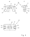
- the first part 1 of a first exemplary embodiment of the other embodiment of the invention shown in FIG. 3 has the shape of a frame with side webs 2 and transverse webs 3 connecting them in the plan view (FIG. 1b).
- the wall thickness of the side webs 2 is approximately 1.5 mm.
- the cross bars 3 are significantly shorter than the side bars 2, so that the frame has an overall elongated shape.
- U-shaped cutouts 4 are provided in the center which, as illustrated in FIG. 3a, are aligned with one another in the side view.
- the cutouts 4 reduce the relatively large height of the side webs 2 in the area of their base and reduce the section modulus there correspondingly with respect to forces which act on these in the plane of the side webs 2 in the expansion direction of the U-cutouts 4.
- locking projections 6 are formed on the inside, that is to say toward the frame interior 5, which have 4 diverging flanks 7 in the opening direction of the cutouts. They interact in a manner to be explained with locking arms on the second part 10 (FIG. 4).
- the side webs 2 On the underside, the side webs 2 have inclined sections 8, which somewhat reduce the height of the side webs 2 towards the cross webs 3; this will still have to be considered.
- FIG. 4 shows the second part 10 belonging to the first part 1 described above. It mainly consists of a cover 11 with arms 12 projecting downwards essentially vertically, but which only have a part of the width of the cover 11, as in particular FIG. 4c illustrated. This also shows that the arms 12 taper downwards.
- a rib 13 is again of smaller width.
- the arms 12 have, at their free ends, outward-facing latching lugs 14.
- the cover 11 has recesses 15 of a width corresponding to the arms 12 where it extends beyond the arms 12 in its longitudinal direction.
- the lid 11 is rounded on the upper side or has sections 16 rounded toward its transverse edges.
- the sausage casing or the like folded into a braid is placed in the U-cutouts 4 of the side webs 2 of the first part 1, so that the braid bridges the two side webs 2 and extends through the frame interior 5.
- the second part 10 with the arms 12 is inserted into the frame interior 5 of the part 1, specifically into the braid bridging the U-cutouts 4 on both sides.
- the outer surfaces of the locking lugs 14 slide along the bevels 7, causing the arms 12 and 12 to compress To a certain extent leads to a spreading of the side webs 2 in the area of the U-cutouts 4 until the latching lugs 14 of the second part 10 engage behind the latching projections 6 on the first part 1.
- the rib 13 presses the braid between the side webs 2 into the interior 5.
- the braid which is clamped between the side webs 2 and the cover 11, is deflected in a wave-like manner by the rib 13.
- the frame interior 5 is enlarged by the fact that the forces acting axially parallel to the sleeve braid on the inner sides of the frame webs 2 'bulge' them outwards (bulge) and in this way with a braid volume which is greater than the nominal volume , created enough space without changing the pressure applied to the braid.
- the braid volume is reduced by shrinking or the like.
- the flexibility of the frame 2, 3 and the associated variability of the frame interior 5 allows that, with the appropriate internal pressure inside the envelope, the bag or the like, this can be broken down, for example, by the escape of liquid or gaseous components of the content without the afterwards sealing pressure of the clip would be reduced or even canceled.
- the spreadability of the U-shaped cutouts 4 in the frame side webs 2 acts in a similar way. As a result of the reduction in the height of the frame web, these can deform elastically when corresponding forces occur and enlarge the passage opening for the casing braid. In addition, as described, this deformability is also used when closing the clip.
- the die can have a flat support surface because the inclined sections 8 on the first part 1 allow the frame webs 2 to be spread apart; the stamp should be adapted to the contour of the lid 11.
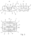
- FIGS. 5 and 6 largely corresponds to a side-by-side doubling of the previously described embodiment, with the proviso that between the a central web 20 is formed in the two outer side webs 2 of the first part 1 '.
- This has - in alignment with the U-shaped cutouts 4 in the side webs 2 - an approximately trapezoidal or trough-shaped cutout 21, the depth of which is less than the depth of the cutouts 4 (FIG. 5a). Since the second part 10 '(FIG. 6) essentially represents a doubling of the part 10 (FIG.
- the cover 11 'of the second part 10' is also provided in the region of the arms 12 with recesses 15 'which here can have the form of notches on the four corners of the cover 11' because of the double arrangement of arms 12 on each side.
- lateral lugs 23 are formed in the middle plane (also having the slot 22) of the second part 10 ′, which can serve, for example, to connect similar second parts to one another by means of film hinges or in another way, to form a chain that stores and successively Processing of plastic clips allowed. It goes without saying that corresponding measures can also be taken with regard to the first clip parts.
- the second parts - can, for example, be lined up on self-adhesive tapes or connected to one another by threads which are pulled off or torn during processing.
- magazines of unconnected adjacent first and second parts of the clips are conceivable, or the loose feeding of the individual parts to a processing device, which aligns them in the correct position before processing.
- the molded bars can also be strung together or connected to one another by self-adhesive tapes or by applied adhesive film and lined up to form the magazine.
- the sprayed bars can also be stacked in a suitable form and then fed to the sealing machine.
Landscapes
- Engineering & Computer Science (AREA)
- Mechanical Engineering (AREA)
- Package Closures (AREA)
- Clamps And Clips (AREA)
- Packages (AREA)
- Bag Frames (AREA)
- Wrappers (AREA)
- Sheet Holders (AREA)
- Vehicle Interior And Exterior Ornaments, Soundproofing, And Insulation (AREA)
- Detergent Compositions (AREA)
Applications Claiming Priority (3)
| Application Number | Priority Date | Filing Date | Title |
|---|---|---|---|
| DE4137478 | 1991-11-14 | ||
| DE4137478A DE4137478A1 (de) | 1991-11-14 | 1991-11-14 | Zweiteiliger kunststoff-clip zum verschliessen von wursthuellen, beuteln o. dgl. |
| PCT/EP1992/002634 WO1993010012A1 (de) | 1991-11-14 | 1992-11-12 | Zweiteiliger kunststoff-clip zum verschliessen von wursthüllen, beuteln o. dgl. |
Publications (2)
| Publication Number | Publication Date |
|---|---|
| EP0611355A1 EP0611355A1 (de) | 1994-08-24 |
| EP0611355B1 true EP0611355B1 (de) | 1995-07-19 |
Family
ID=6444808
Family Applications (1)
| Application Number | Title | Priority Date | Filing Date |
|---|---|---|---|
| EP92923429A Expired - Lifetime EP0611355B1 (de) | 1991-11-14 | 1992-11-12 | Zweiteiliger kunststoff-clip zum verschliessen von wursthüllen, beuteln o. dgl. |
Country Status (18)
| Country | Link |
|---|---|
| US (1) | US5546637A (cs) |
| EP (1) | EP0611355B1 (cs) |
| JP (1) | JP2986913B2 (cs) |
| AT (1) | ATE125225T1 (cs) |
| AU (1) | AU664572B2 (cs) |
| BR (1) | BR9206749A (cs) |
| CA (1) | CA2123231A1 (cs) |
| CZ (1) | CZ103294A3 (cs) |
| DE (2) | DE4137478A1 (cs) |
| DK (1) | DK0611355T3 (cs) |
| ES (1) | ES2076786T3 (cs) |
| FI (1) | FI942242A0 (cs) |
| GR (1) | GR3017450T3 (cs) |
| HU (1) | HU216552B (cs) |
| NO (1) | NO941723D0 (cs) |
| RU (1) | RU94030462A (cs) |
| SK (1) | SK51294A3 (cs) |
| WO (1) | WO1993010012A1 (cs) |
Families Citing this family (20)
| Publication number | Priority date | Publication date | Assignee | Title |
|---|---|---|---|---|
| DE4401111A1 (de) * | 1994-01-17 | 1995-07-20 | Poly Clip System Gmbh | Verschließvorrichtung für Kunststoffclips |
| US20030105298A1 (en) * | 1998-06-16 | 2003-06-05 | Genentech, Inc. | Secreted and transmembrane polypeptides and nucleic acids encoding the same |
| US20030109681A1 (en) * | 1998-06-10 | 2003-06-12 | Genentech, Inc. | Secreted and transmembrane polypeptides and nucleic acids encoding the same |
| US7244817B2 (en) * | 1998-09-10 | 2007-07-17 | Genentech, Inc. | Pro1357 polypeptide |
| US7109292B2 (en) * | 1999-03-08 | 2006-09-19 | Genentech, Inc. | Secreted and transmembrane polypeptides and nucleic acids encoding the same |
| GB0003173D0 (en) * | 2000-02-12 | 2000-04-05 | Smiths Industries Plc | Clamps |
| US6772484B2 (en) * | 2000-09-28 | 2004-08-10 | Toyoda Gosei Co., Ltd | Mounting structure for mounting a resin molded article to a body panel |
| US7202335B2 (en) * | 2001-12-06 | 2007-04-10 | Genentech, Inc. | PRO300 polypeptides |
| US6622355B2 (en) * | 2002-01-03 | 2003-09-23 | Illinois Tool Works Inc. | Mounting structure |
| US7118318B2 (en) * | 2003-11-20 | 2006-10-10 | Bellsouth Intellectual Property Corporation | Wire protector and retainer |
| US7571518B2 (en) * | 2004-06-18 | 2009-08-11 | Brett Davidson | Clamp for closing a flexible bag |
| DE102005042856B4 (de) * | 2005-09-08 | 2007-08-09 | Frans Vermee Gmbh | Verschließklammer |
| DE102006017537A1 (de) * | 2006-04-13 | 2007-10-18 | Poly-Clip System Gmbh & Co. Kg | Verschlussklammer und Verfahren zu deren Herstellung |
| US20080047112A1 (en) * | 2006-08-22 | 2008-02-28 | Theodore Calvin Hoekstra | Clip assembly for fuel door release cable |
| GB2455085A (en) * | 2007-11-27 | 2009-06-03 | Fergus Johnathan Ardern | Clip comprising a resiliently deformable split ring |
| JP5513952B2 (ja) * | 2010-03-26 | 2014-06-04 | 矢崎総業株式会社 | ホルダの取付構造 |
| CH704272A2 (de) | 2010-12-24 | 2012-06-29 | Viktor Schnyder | Clip-Verschluss. |
| US20120198668A1 (en) * | 2011-02-08 | 2012-08-09 | Helen Butler | Stay-a two part device that snaps in place over shoelces |
| DE202018002267U1 (de) * | 2018-05-08 | 2019-08-13 | Mk Technology Gmbh | Verbindungselement für eine Körperschutzpanzerung, insbesondere für den Schlag- und/oder Stichschutz, sowie Körperschutzpanzerung |
| CN117022813B (zh) * | 2023-08-08 | 2025-09-02 | 泰安市海之润食品有限公司 | 包含汤料的带刺肉类软罐头的辅助包装装置及方法 |
Family Cites Families (14)
| Publication number | Priority date | Publication date | Assignee | Title |
|---|---|---|---|---|
| DE1023693B (de) * | 1955-09-03 | 1958-01-30 | Heinrich Klein Soetebier | Vorrichtung zum Verschliessen von Wursthuellen, Tueten, Beuteln od. dgl. |
| FR1326485A (fr) * | 1962-03-27 | 1963-05-10 | Dispositif d'attache, utilisable notamment comme lien pour les saucissons et analogues | |
| US3171184A (en) * | 1962-10-30 | 1965-03-02 | Posse Nils Lage Wilhelm | Clamp |
| US3164250A (en) * | 1963-11-22 | 1965-01-05 | Kwik Lok | Polystyrene multi-closure strip adapted for separation into individual closures |
| GB1528002A (en) | 1975-03-26 | 1978-10-11 | United Carr Ltd | Clips for elongate members |
| US4128922A (en) * | 1977-08-19 | 1978-12-12 | Hutchison Charles L | Sealing device |
| US4275485A (en) * | 1979-12-10 | 1981-06-30 | Hutchison Charles L | Sealing devices |
| US4405161A (en) * | 1981-06-09 | 1983-09-20 | A. Steven Young | Wellhead security apparatus |
| US4416038A (en) * | 1982-05-24 | 1983-11-22 | Adecon, Inc. | Balloon clip |
| ZA85404B (en) * | 1984-02-01 | 1985-09-25 | Squibb & Sons Inc | Ostomy bag closure means |
| DK153013C (da) * | 1985-08-20 | 1988-10-31 | Ice Pack Service Ag | Lukkeklemme til poser |
| DE3738881A1 (de) * | 1987-11-16 | 1989-05-24 | Ice Pack Service Ag | Verschluss zum verschliessen von kunststoffbeuteln und dergleichen |
| DE4032750A1 (de) * | 1990-10-16 | 1992-04-23 | Kummerow Walter | Verschliesselement |
| US5189766A (en) * | 1992-01-31 | 1993-03-02 | Alcatel Network Systems, Inc. | Multiple bit height snap fit cable holder apparatus |
-
1991
- 1991-11-14 DE DE4137478A patent/DE4137478A1/de not_active Withdrawn
-
1992
- 1992-11-12 SK SK512-94A patent/SK51294A3/sk unknown
- 1992-11-12 JP JP5508984A patent/JP2986913B2/ja not_active Expired - Lifetime
- 1992-11-12 WO PCT/EP1992/002634 patent/WO1993010012A1/de not_active Ceased
- 1992-11-12 CZ CZ941032A patent/CZ103294A3/cs unknown
- 1992-11-12 CA CA002123231A patent/CA2123231A1/en not_active Abandoned
- 1992-11-12 DK DK92923429.2T patent/DK0611355T3/da active
- 1992-11-12 DE DE59202985T patent/DE59202985D1/de not_active Expired - Fee Related
- 1992-11-12 US US08/244,095 patent/US5546637A/en not_active Expired - Fee Related
- 1992-11-12 AT AT92923429T patent/ATE125225T1/de not_active IP Right Cessation
- 1992-11-12 ES ES92923429T patent/ES2076786T3/es not_active Expired - Lifetime
- 1992-11-12 BR BR9206749A patent/BR9206749A/pt not_active IP Right Cessation
- 1992-11-12 AU AU29261/92A patent/AU664572B2/en not_active Ceased
- 1992-11-12 HU HU9401322A patent/HU216552B/hu not_active IP Right Cessation
- 1992-11-12 RU RU94030462/13A patent/RU94030462A/ru unknown
- 1992-11-12 EP EP92923429A patent/EP0611355B1/de not_active Expired - Lifetime
-
1994
- 1994-05-09 NO NO941723A patent/NO941723D0/no unknown
- 1994-05-13 FI FI942242A patent/FI942242A0/fi unknown
-
1995
- 1995-09-20 GR GR950402577T patent/GR3017450T3/el unknown
Also Published As
| Publication number | Publication date |
|---|---|
| FI942242A7 (fi) | 1994-05-13 |
| WO1993010012A1 (de) | 1993-05-27 |
| NO941723L (no) | 1994-05-09 |
| NO941723D0 (no) | 1994-05-09 |
| EP0611355A1 (de) | 1994-08-24 |
| CA2123231A1 (en) | 1993-05-27 |
| GR3017450T3 (en) | 1995-12-31 |
| CZ103294A3 (en) | 1994-10-19 |
| US5546637A (en) | 1996-08-20 |
| JP2986913B2 (ja) | 1999-12-06 |
| HU9401322D0 (en) | 1994-08-29 |
| ES2076786T3 (es) | 1995-11-01 |
| DE59202985D1 (de) | 1995-08-24 |
| BR9206749A (pt) | 1995-03-01 |
| HUT69621A (en) | 1995-09-28 |
| FI942242A0 (fi) | 1994-05-13 |
| DE4137478A1 (de) | 1993-05-19 |
| AU2926192A (en) | 1993-06-15 |
| ATE125225T1 (de) | 1995-08-15 |
| RU94030462A (ru) | 1997-03-10 |
| DK0611355T3 (da) | 1995-09-11 |
| JPH07504870A (ja) | 1995-06-01 |
| SK51294A3 (en) | 1994-09-07 |
| AU664572B2 (en) | 1995-11-23 |
| HU216552B (hu) | 1999-07-28 |
Similar Documents
| Publication | Publication Date | Title |
|---|---|---|
| EP0611355B1 (de) | Zweiteiliger kunststoff-clip zum verschliessen von wursthüllen, beuteln o. dgl. | |
| DE69626046T2 (de) | Anschlusselement und Klemmverbinder | |
| DE1665163C3 (de) | Verbinder zum Herstellen lötfreier elektrischer Verbindungen mit Leitern eines Mehrfach-Flachkabels | |
| EP1103088B1 (de) | Buchsenkontakt | |
| DE2502663C2 (de) | Befestiger | |
| EP0189821B1 (de) | Elektrischer Doppelflachfederkontakt | |
| EP1400619B1 (de) | Werkzeugträger für Schiebernadeln und Versandeinheit | |
| DE1765818B2 (de) | Verbindungsklemme zum Andrücken an elektrische Drähte | |
| DE3231484C2 (cs) | ||
| DE7429889U (de) | Kabelbaum-Klemm vorrichtung | |
| DE69807618T2 (de) | Verpackung für Nähfadenanker | |
| DE1465147B1 (de) | Elektrische Mehrfachsteckverbindung | |
| DE29919090U1 (de) | Chirurgisches Verbindungselement zur Fixierung benachbart angeordneter Knochenplatten | |
| EP0842096A1 (de) | Magazinierbarer streifen von verschlussklammern für schläuche und beutel | |
| DE2516005C3 (de) | Binder zum Zusammenbinden und/oder Befestigen von Gegenständen wie Kabeln | |
| DE102005047187B4 (de) | Chirurgisches Befestigungselement für ein chirurgisches Profilelement eines chirurgischen Behälters, Profilelement, Satz solcher Befestigungs- oder Profilelemente, Behälter | |
| DE2906544C3 (de) | Klemmbefestigung für Nadelstreifen in einer U-förmigen Ausnehmung eines Nadelstabes oder einer Nadelwalze | |
| DE3339313A1 (de) | Stecker fuer schwachstromanlagen | |
| DE4332929C1 (de) | Installationsdose für elektrische Installationsgeräte | |
| DE19652624C2 (de) | Elektrischer Verbinder | |
| EP1469568B1 (de) | Steckkontaktelement und Verfahren zur Herstellung eines Gehäuseteils für dieses | |
| DE4400013C2 (de) | Schneidvorrichtung | |
| DE19530241A1 (de) | Schraubenlose Klemme | |
| DE9304392U1 (de) | Kontaktelement mit Schneidklemm- und Crimpanschluß | |
| DE3332353C2 (cs) |
Legal Events
| Date | Code | Title | Description |
|---|---|---|---|
| PUAI | Public reference made under article 153(3) epc to a published international application that has entered the european phase |
Free format text: ORIGINAL CODE: 0009012 |
|
| 17P | Request for examination filed |
Effective date: 19940324 |
|
| AK | Designated contracting states |
Kind code of ref document: A1 Designated state(s): AT BE CH DE DK ES FR GB GR IE IT LI LU NL SE |
|
| 17Q | First examination report despatched |
Effective date: 19941128 |
|
| GRAA | (expected) grant |
Free format text: ORIGINAL CODE: 0009210 |
|
| AK | Designated contracting states |
Kind code of ref document: B1 Designated state(s): AT BE CH DE DK ES FR GB GR IE IT LI LU NL SE |
|
| REF | Corresponds to: |
Ref document number: 125225 Country of ref document: AT Date of ref document: 19950815 Kind code of ref document: T |
|
| REG | Reference to a national code |
Ref country code: IE Ref legal event code: FG4D Free format text: 64588 |
|
| REF | Corresponds to: |
Ref document number: 59202985 Country of ref document: DE Date of ref document: 19950824 |
|
| ET | Fr: translation filed | ||
| REG | Reference to a national code |
Ref country code: DK Ref legal event code: T3 |
|
| ITF | It: translation for a ep patent filed | ||
| GBT | Gb: translation of ep patent filed (gb section 77(6)(a)/1977) |
Effective date: 19950914 |
|
| REG | Reference to a national code |
Ref country code: ES Ref legal event code: FG2A Ref document number: 2076786 Country of ref document: ES Kind code of ref document: T3 |
|
| REG | Reference to a national code |
Ref country code: GR Ref legal event code: FG4A Free format text: 3017450 |
|
| PLBE | No opposition filed within time limit |
Free format text: ORIGINAL CODE: 0009261 |
|
| STAA | Information on the status of an ep patent application or granted ep patent |
Free format text: STATUS: NO OPPOSITION FILED WITHIN TIME LIMIT |
|
| 26N | No opposition filed | ||
| PGFP | Annual fee paid to national office [announced via postgrant information from national office to epo] |
Ref country code: GR Payment date: 19960829 Year of fee payment: 5 |
|
| PGFP | Annual fee paid to national office [announced via postgrant information from national office to epo] |
Ref country code: IE Payment date: 19961023 Year of fee payment: 5 |
|
| PGFP | Annual fee paid to national office [announced via postgrant information from national office to epo] |
Ref country code: SE Payment date: 19961122 Year of fee payment: 5 |
|
| PGFP | Annual fee paid to national office [announced via postgrant information from national office to epo] |
Ref country code: LU Payment date: 19961201 Year of fee payment: 5 |
|
| PG25 | Lapsed in a contracting state [announced via postgrant information from national office to epo] |
Ref country code: LU Free format text: LAPSE BECAUSE OF NON-PAYMENT OF DUE FEES Effective date: 19971112 Ref country code: IE Free format text: LAPSE BECAUSE OF NON-PAYMENT OF DUE FEES Effective date: 19971112 |
|
| PG25 | Lapsed in a contracting state [announced via postgrant information from national office to epo] |
Ref country code: SE Free format text: LAPSE BECAUSE OF NON-PAYMENT OF DUE FEES Effective date: 19971113 |
|
| PG25 | Lapsed in a contracting state [announced via postgrant information from national office to epo] |
Ref country code: GR Free format text: LAPSE BECAUSE OF NON-PAYMENT OF DUE FEES Effective date: 19971130 |
|
| EUG | Se: european patent has lapsed |
Ref document number: 92923429.2 |
|
| PGFP | Annual fee paid to national office [announced via postgrant information from national office to epo] |
Ref country code: DE Payment date: 20001031 Year of fee payment: 9 |
|
| PGFP | Annual fee paid to national office [announced via postgrant information from national office to epo] |
Ref country code: GB Payment date: 20011025 Year of fee payment: 10 |
|
| PGFP | Annual fee paid to national office [announced via postgrant information from national office to epo] |
Ref country code: FR Payment date: 20011119 Year of fee payment: 10 |
|
| PGFP | Annual fee paid to national office [announced via postgrant information from national office to epo] |
Ref country code: DK Payment date: 20011122 Year of fee payment: 10 |
|
| PGFP | Annual fee paid to national office [announced via postgrant information from national office to epo] |
Ref country code: NL Payment date: 20011123 Year of fee payment: 10 Ref country code: BE Payment date: 20011123 Year of fee payment: 10 Ref country code: AT Payment date: 20011123 Year of fee payment: 10 |
|
| PGFP | Annual fee paid to national office [announced via postgrant information from national office to epo] |
Ref country code: ES Payment date: 20011126 Year of fee payment: 10 Ref country code: CH Payment date: 20011126 Year of fee payment: 10 |
|
| REG | Reference to a national code |
Ref country code: GB Ref legal event code: IF02 |
|
| PG25 | Lapsed in a contracting state [announced via postgrant information from national office to epo] |
Ref country code: DE Free format text: LAPSE BECAUSE OF NON-PAYMENT OF DUE FEES Effective date: 20020702 |
|
| PG25 | Lapsed in a contracting state [announced via postgrant information from national office to epo] |
Ref country code: GB Free format text: LAPSE BECAUSE OF NON-PAYMENT OF DUE FEES Effective date: 20021112 Ref country code: AT Free format text: LAPSE BECAUSE OF NON-PAYMENT OF DUE FEES Effective date: 20021112 |
|
| PG25 | Lapsed in a contracting state [announced via postgrant information from national office to epo] |
Ref country code: ES Free format text: LAPSE BECAUSE OF NON-PAYMENT OF DUE FEES Effective date: 20021113 |
|
| PG25 | Lapsed in a contracting state [announced via postgrant information from national office to epo] |
Ref country code: LI Free format text: LAPSE BECAUSE OF NON-PAYMENT OF DUE FEES Effective date: 20021130 Ref country code: CH Free format text: LAPSE BECAUSE OF NON-PAYMENT OF DUE FEES Effective date: 20021130 Ref country code: BE Free format text: LAPSE BECAUSE OF NON-PAYMENT OF DUE FEES Effective date: 20021130 |
|
| PG25 | Lapsed in a contracting state [announced via postgrant information from national office to epo] |
Ref country code: DK Free format text: LAPSE BECAUSE OF NON-PAYMENT OF DUE FEES Effective date: 20021231 |
|
| BERE | Be: lapsed |
Owner name: *NIEDECKER HERBERT Effective date: 20021130 |
|
| PG25 | Lapsed in a contracting state [announced via postgrant information from national office to epo] |
Ref country code: NL Free format text: LAPSE BECAUSE OF NON-PAYMENT OF DUE FEES Effective date: 20030601 |
|
| GBPC | Gb: european patent ceased through non-payment of renewal fee | ||
| REG | Reference to a national code |
Ref country code: DK Ref legal event code: EBP |
|
| REG | Reference to a national code |
Ref country code: CH Ref legal event code: PL |
|
| PG25 | Lapsed in a contracting state [announced via postgrant information from national office to epo] |
Ref country code: FR Free format text: LAPSE BECAUSE OF NON-PAYMENT OF DUE FEES Effective date: 20030731 |
|
| NLV4 | Nl: lapsed or anulled due to non-payment of the annual fee |
Effective date: 20030601 |
|
| REG | Reference to a national code |
Ref country code: FR Ref legal event code: ST |
|
| REG | Reference to a national code |
Ref country code: ES Ref legal event code: FD2A Effective date: 20031213 |
|
| PG25 | Lapsed in a contracting state [announced via postgrant information from national office to epo] |
Ref country code: IT Free format text: LAPSE BECAUSE OF NON-PAYMENT OF DUE FEES;WARNING: LAPSES OF ITALIAN PATENTS WITH EFFECTIVE DATE BEFORE 2007 MAY HAVE OCCURRED AT ANY TIME BEFORE 2007. THE CORRECT EFFECTIVE DATE MAY BE DIFFERENT FROM THE ONE RECORDED. Effective date: 20051112 |