EP0611593B1 - Procédé continu d'agglomération en lit fluidisé - Google Patents
Procédé continu d'agglomération en lit fluidisé Download PDFInfo
- Publication number
- EP0611593B1 EP0611593B1 EP94101545A EP94101545A EP0611593B1 EP 0611593 B1 EP0611593 B1 EP 0611593B1 EP 94101545 A EP94101545 A EP 94101545A EP 94101545 A EP94101545 A EP 94101545A EP 0611593 B1 EP0611593 B1 EP 0611593B1
- Authority
- EP
- European Patent Office
- Prior art keywords
- fluidized bed
- air
- solid
- granulating liquid
- fluidized
- Prior art date
- Legal status (The legal status is an assumption and is not a legal conclusion. Google has not performed a legal analysis and makes no representation as to the accuracy of the status listed.)
- Expired - Lifetime
Links
- 238000000034 method Methods 0.000 title claims description 22
- 230000008569 process Effects 0.000 title claims description 20
- 238000005054 agglomeration Methods 0.000 title claims description 12
- 230000002776 aggregation Effects 0.000 title claims description 12
- 239000007788 liquid Substances 0.000 claims description 46
- 239000007787 solid Substances 0.000 claims description 39
- 239000008187 granular material Substances 0.000 claims description 37
- 239000000725 suspension Substances 0.000 claims description 6
- 239000000203 mixture Substances 0.000 claims description 5
- 239000000428 dust Substances 0.000 claims description 4
- 238000005507 spraying Methods 0.000 claims description 4
- 241000446313 Lamella Species 0.000 claims 1
- 239000003570 air Substances 0.000 description 40
- 239000002245 particle Substances 0.000 description 23
- 239000000843 powder Substances 0.000 description 12
- 238000001035 drying Methods 0.000 description 8
- 238000005469 granulation Methods 0.000 description 8
- 230000003179 granulation Effects 0.000 description 8
- 239000000126 substance Substances 0.000 description 5
- 239000000853 adhesive Substances 0.000 description 4
- 230000001070 adhesive effect Effects 0.000 description 4
- 239000011230 binding agent Substances 0.000 description 4
- 230000004087 circulation Effects 0.000 description 4
- 239000012530 fluid Substances 0.000 description 4
- 230000015572 biosynthetic process Effects 0.000 description 3
- 238000009826 distribution Methods 0.000 description 3
- 239000003380 propellant Substances 0.000 description 3
- 230000008901 benefit Effects 0.000 description 2
- 230000008859 change Effects 0.000 description 2
- 238000010276 construction Methods 0.000 description 2
- 238000011161 development Methods 0.000 description 2
- 238000010586 diagram Methods 0.000 description 2
- 239000007921 spray Substances 0.000 description 2
- 229920002472 Starch Polymers 0.000 description 1
- 238000005253 cladding Methods 0.000 description 1
- 238000010924 continuous production Methods 0.000 description 1
- 238000013461 design Methods 0.000 description 1
- 230000000694 effects Effects 0.000 description 1
- 238000005243 fluidization Methods 0.000 description 1
- 230000006872 improvement Effects 0.000 description 1
- 230000007774 longterm Effects 0.000 description 1
- 238000004519 manufacturing process Methods 0.000 description 1
- 238000005259 measurement Methods 0.000 description 1
- 235000011837 pasties Nutrition 0.000 description 1
- 230000000704 physical effect Effects 0.000 description 1
- 230000009467 reduction Effects 0.000 description 1
- 230000001105 regulatory effect Effects 0.000 description 1
- 238000012216 screening Methods 0.000 description 1
- 238000000926 separation method Methods 0.000 description 1
- 239000004449 solid propellant Substances 0.000 description 1
- 235000019698 starch Nutrition 0.000 description 1
- 239000008107 starch Substances 0.000 description 1
- 230000009897 systematic effect Effects 0.000 description 1
- 230000000007 visual effect Effects 0.000 description 1
- 229920003169 water-soluble polymer Polymers 0.000 description 1
- 238000009736 wetting Methods 0.000 description 1
Images


Classifications
-
- B—PERFORMING OPERATIONS; TRANSPORTING
- B01—PHYSICAL OR CHEMICAL PROCESSES OR APPARATUS IN GENERAL
- B01J—CHEMICAL OR PHYSICAL PROCESSES, e.g. CATALYSIS OR COLLOID CHEMISTRY; THEIR RELEVANT APPARATUS
- B01J2/00—Processes or devices for granulating materials, e.g. fertilisers in general; Rendering particulate materials free flowing in general, e.g. making them hydrophobic
- B01J2/16—Processes or devices for granulating materials, e.g. fertilisers in general; Rendering particulate materials free flowing in general, e.g. making them hydrophobic by suspending the powder material in a gas, e.g. in fluidised beds or as a falling curtain
-
- Y—GENERAL TAGGING OF NEW TECHNOLOGICAL DEVELOPMENTS; GENERAL TAGGING OF CROSS-SECTIONAL TECHNOLOGIES SPANNING OVER SEVERAL SECTIONS OF THE IPC; TECHNICAL SUBJECTS COVERED BY FORMER USPC CROSS-REFERENCE ART COLLECTIONS [XRACs] AND DIGESTS
- Y10—TECHNICAL SUBJECTS COVERED BY FORMER USPC
- Y10S—TECHNICAL SUBJECTS COVERED BY FORMER USPC CROSS-REFERENCE ART COLLECTIONS [XRACs] AND DIGESTS
- Y10S118/00—Coating apparatus
- Y10S118/05—Fluidized bed
Definitions
- the invention relates to a process for the continuous fluidized bed agglomeration of a powdery solid which is sprayed together with a granulating liquid into a fluidized bed operated with fluidizing gas and in which the finished granulate is discharged from the fluidized bed by an air classifier.
- the powder to be agglomerated is placed in the apparatus and brought into the fluidized bed state with the aid of the fluidizing gas.
- the fluidized powder is sprayed with the granulating liquid and thus brought into a sticky state, so that the formation of granules begins. If the granules have the desired size, drying is usually carried out with the liquid supply switched off in the same apparatus.
- the fluidization behavior of the solid is due to the constantly changing particle size from powder to the finished granulate is subject to constant change, whereby smaller particles in the fluidized bed require a lower inflow velocity than large particles. For this reason, the inflow velocity is usually adapted to the particle size. A too high inflow speed leads to discharge of product from the bed; if the inflow velocity is too low, the bed "collapses".
- a granulate with reproducibly adjustable, constant physical properties can only be produced if it is process-related constant granulation conditions in the fluidized bed apparatus are observed.
- the granulation conditions remain constant if the fluidized bed content is kept constant, so that in the stationary state the solid mass fed into the fluidized bed is equal to the mass of the finished granules removed from the bed.
- the finished granulate is preferably discharged from the fluidized bed centrally through an inlet weir arranged concentrically with the three-substance nozzle on the air classifier.
- the solids content of the fluidized bed is kept constant by a control circuit in which the pressure loss of the fluidizing air in the fluidized bed is used as a measured variable and the flow rate of the classifying air in the air classifier as a manipulated variable.
- the inlet cross-section of the inlet weir can be adjusted on the air classifier.
- Another variant is that part of the solid to be granulated is already added to the granulating liquid in finely divided form. A suspension of solid and liquid is therefore used as the granulating liquid.
- the fine grain fractions in the fluidized bed are expediently separated using an external dust filter and recirculated to the fluidized bed via the solid propellant air stream.
- a further improvement is that the product moisture is measured in the fluidized bed and is constantly regulated by adjusting the amount of granulating liquid or suspension metered into the fluidized bed.
- the device for carrying out the method consists of a fluidized bed granulator with an inflow base and a nozzle for spraying the fluidized solid with the granulating liquid, as well as feeders for the solid and the granulating liquid and an air classifier for sifting discharge of the finished granulate.
- a three-component nozzle for spraying a three-phase mixture of solid, granulating liquid and propellant air is arranged axially in the center of the fluidized bed granulator.
- a height-adjustable mixing tube is advantageously attached above the spray nozzle.
- the inlet cross section of the inlet weir on the wind sifter can be adjusted by a blind consisting of a rotatable sector lamellar disc.
- the invention enables the continuous production of an almost spherical granulate with a narrow particle size distribution under constant and reproducible operating conditions in which the statistical particle size distribution is always the same in the fluidized bed.
- Another advantage lies in the uniform, shell-shaped granulate structure, which is essentially due to the amount of granulating liquid and powder mass added in a coordinated quantity ratio. Additional further advantages are also pointed out in the detailed description below.
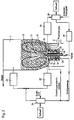
- the fluidized bed apparatus (WSG apparatus) 1 is continuously supplied with fluidizing air 2, granulating liquid 3 and the powdery solid 4 to be agglomerated through a pneumatic delivery line 5 from below.
- the visual, driving and fluidizing air streams fed in leave the WSG apparatus 1 via the exhaust air line 7.
- the entrained dust is separated in an external dust filter 8 and recirculated into the WSG apparatus 1 through the pneumatic delivery line 5.
- the driving air for the pneumatic delivery line 5 is supplied via the connection 9 and the solid to be agglomerated via the connection 10.
- the solid is fed into the fluidized bed 13 via the cladding tube 11 of a three-component nozzle 12 arranged centrally in the WSG apparatus 1 (see FIG. 2).
- the fluidizing air 2 is supplied to the WSG apparatus 1 in the inflow base 14.
- a wind classifier 15 is also arranged centrally and concentrically with the three-substance nozzle 12 at the classifying discharge of the granulate.
- the powdery solid is blown through the pneumatic delivery line into the annular gap of the three-component nozzle.
- the granulating liquid 3 is also injected into the WSG apparatus by means of propellant air through the inner tube 16.
- a spray cone 17 consisting of the three-phase mixture of powder, liquid and air is thereby generated at the nozzle head.
- the granules continuously growing in the fluidized bed 13 pass over time several times via an inlet weir (see FIGS. 3 to 5) into the air classifier 15, where the fine fraction is separated off and returned to the WSG apparatus 1.
- the central arrangement of the powder and liquid addition on the one hand and the air classifier on the other hand enable the setting of zones of different moisture in the fluidized bed 13.
- the actual agglomeration takes place in the center of the fluidized bed 13, which is favored by the high humidity due to the liquid feed.
- the impulse of the supplied motive air flows causes a circulation movement of the fluidized bed. Before the granules get into the air classifier 15, they have to cross the inflow floor 14 and come into intensive contact with the hot and dry fluidizing air there. This ensures that only dry granules fall through the air classifier 15. In this way, residual product moisture of less than 8% is obtained without additional drying.
- a mixing tube 18 is mounted centrally, the height of which can be adjusted above the inflow floor 14.
- the zone of high humidity is concentrated even more strongly on the central region of the fluidized bed 13 through the mixing tube 18. This gives the wetted particles an even higher adhesive force and is therefore better able to accumulate the powder fed into this area. This measure leads to a reduction in the integral moisture in the fluidized bed 13.
- the system described allows the continuous agglomeration of powdery solids under constant operating conditions. However, if higher demands are placed on the physical product properties, it is necessary to take additional control measures to ensure long-term stable operation. It has been found that these requirements can be taken into account if the particle moisture and the temperature in the fluidized bed and the fluidized bed content (bed height) are determined in certain Limits are kept constant. Agglomeration only occurs when there is sufficient moisture. The temperature control of the fluidized bed is necessary so that the granulating liquid can be removed by drying after it has fulfilled its function as a binder.
- the measured moisture value is compared by a separate controller 20 with a predetermined target value and the metering pump 21 for the granulating liquid is adjusted so that the difference between the moisture measured value and the predetermined target value is minimized.
- the moisture in the fluidized bed can be kept constant in a narrow area.
- a mode of operation that is too dry would hinder the agglomeration of the particles, since in this case the mutual adhesive forces resulting from the liquid bridges would not be sufficient.
- an increase in bed moisture would increase the interparticle Increase adhesive forces and thus hinder the movement of the individual particles. If the humidity is too high, the fluidized bed finally collapses due to over-moisture (formation of a pasty mass).
- the granulating liquid is metered into the fluidized bed as a pure liquid, it is first necessary to wet the particles until the adhesive forces mentioned become effective through bridging.
- a suspension of the solid to be granulated and the liquid is already used from the outset as the granulating liquid, partially wetted particles with improved agglomeration capacity are already present. These particles then hit larger granules to which they spontaneously adhere. At the same time, because of the sticky surface, they are able to add further powder particles. It has been found that the agglomeration process as a whole is promoted by using a solid suspension instead of a solid-free granulating liquid, so that the integral moisture in the fluidized bed can be reduced. This facilitates drying and saves energy costs.
- part of the powdery solid 4 is branched off and mixed with the granulating liquid 3.
- the differential pressure signal is fed to a controller 24, which adjusts the sifting gas volume flow required for the wind sifter 15 in such a way that the differential pressure remains constant and corresponds to a preset desired value.
- the sifting gas volume flow is therefore used as the manipulated variable.
- An increase in the flow of classifying gas leads to an increase in the amount of granules discharged.
- the controller 24 must contain an adjustable valve.
- the inlet cross-section of the inlet weir on the air classifier 15 can also be used as a manipulated variable for the control instead of the sight gas volume flow.
- FIGS. 3 to 5 An inlet weir with an adjustable, variable inlet cross section is shown in FIGS. 3 to 5.
- the inlet weir 25 has a truncated cone-shaped blind 27 which is flush with the three-substance nozzle 12 (see FIGS. 2 and 3). 4, the blind consists of two stacked sector lamellar disks 28 and 29 which are arranged one above the other.
- the inlet cross section of the inlet openings 30 above the sifter channels 26 located below can be changed (corresponding to the angle of rotation ⁇ ).
- the sector disk disc is rotated with a servomotor.
- the individual slats 31 of the upper sector disk 28 can optionally be rotated relative to the lower sector disk 29, so that the inlet cross section of the inlet openings 32 (corresponding to the angles of rotation ⁇ 1, ⁇ 2, ⁇ 3 , ...) can be set individually.
- This individual adjustment comes into play when the air classifier 15 is divided into a plurality of segment-shaped chambers which are assigned to the inlet openings 32. In this way, individual chambers can be closed, while the remaining chambers are optimally charged with the product to be viewed. In this mode of operation, the chambers are either closed or are operated under optimal conditions.
- a suitable granulating liquid is selected depending on the solid to be granulated according to the prior art from the point of view of the function of a binder between the particles to be agglomerated.
- the task of the granulating liquid initially consists in the production of liquid bridges between individual solid particles. Due to the capillary negative pressure and surface tension of the liquid, the particles are held together in the moist state.
- the powdery solid can also contain other components, e.g. additional binders, e.g. Contain starch or other water-soluble polymers.
- additional binders e.g. Contain starch or other water-soluble polymers.
Landscapes
- Chemical & Material Sciences (AREA)
- Organic Chemistry (AREA)
- Chemical Kinetics & Catalysis (AREA)
- Glanulating (AREA)
- Combined Means For Separation Of Solids (AREA)
- Drying Of Solid Materials (AREA)
Claims (10)
- Procédé d'agglomération continue en lit fluidisé d'une matière solide (4) en poudre qui est pulvérisée conjointement avec un liquide de granulation (3) dans un lit tourbillonnaire (13) actionné par de l'air fluidisant (2) et dans lequel le produit final granulé est déchargé du lit tourbillonnaire (13) par un aéroclasseur (15), caractérisé en ce que le liquide de granulation (3) est amené conjointement avec de l'air propulseur au centre du fond d'admission (14) du lit tourbillonnaire (13) par une buse ternaire (13) et, en même temps, la matière solide (4) est injectée dans le lit tourbillonnaire (13), au moyen d'un courant d'air propulseur amené séparément et concentriquement, par la fente annulaire de la buse ternaire (12), ce qui a pour effet de produire au centre du lit tourbillonnaire (13) un mélange à trois phases de matière solide (4), de liquide de granulation (3) et d'air propulseur.
- Procédé suivant la revendication 1, caractérisé en ce que le produit granulé final est déchargé du lit tourbillonnaire (13) par un déversoir d'entrée (25) disposé sur l'aéroclasseur (15) concentriquement par rapport à la buse ternaire (12).
- Procédé suivant les revendications 1 et 2, caractérisé en ce que la quantité de matière solide présente dans le lit tourbillonnaire (13) est maintenue constante par un circuit de régulation dans lequela) la chute de pression de l'air fluidisant dans le lit tourbillonnaire (13) est utilisée comme grandeur de mesure etb) le débit de l'air agissant dans l'aéroclasseur (15) est utilisé comme grandeur réglante.
- Procédé suivant les revendications 1 et 2, caractérisé en ce que la quantité de matière solide présente dans le lit tourbillonnaire est maintenue constante par un circuit de réglage dans lequela) la chute de pression de l'air fluidisant dans le lit tourbillonnaire est utilisée comme grandeur de mesure etb) la section transversale d'admission du déversoir (25) d'accès à l'aéroclasseur (15) est utilisée comme grandeur réglante.
- Procédé suivant les revendications 1 à 4, caractérisé en ce qu'une partie de la matière solide (4) à granuler est ajoutée sous une forme finement divisée au liquide de granulation (3).
- Procédé suivant les revendications 1 à 5, caractérisé en ce que la fraction en fines particules dans le lit tourbillonnaire (13) est séparée par un filtre à poussière (8) disposé extérieurement et est recyclée au lit tourbillonnaire (13) par le courant (5) de matière solide et d'air propulseur.
- Procédé suivant les revendications 1 à 6, caractérisé en ce que l'humidité du produit est mesurée dans le lit tourbillonnaire (13) et est réglée à une valeur constante par compensation de la quantité de liquide de granulation ou de suspension injectée dans le lit tourbillonnaire.
- Dispositif pour la mise en oeuvre du procédé, constitué d'un granulateur (1) à lit tourbillonnaire comprenant un fond d'admission (14) et une buse de pulvérisation de la matière solide (4) fluidisée avec un liquide de granulation (3) et des arrivées de matière solide (4) et du liquide de granulation (3), ainsi que d'un aéroclasseur (15) permettant la décharge par classement du produit final granulé, caractérisé en ce qu'une buse ternaire (12) est disposée axialement au centre du granulateur (1) à lit tourbillonnaire pour la pulvérisation d'un mélange à trois phases de matière solide, de liquide de granulation et d'air propulseur.
- Dispositif suivant la revendication 8, caractérisé en ce qu'un tube mélangeur (18) réglable en hauteur est adapté axialement au-dessus de la buse ternaire (12).
- Dispositif suivant les revendications 8 et 9, caractérisé en ce que la section transversale d'admission du déversoir (25) d'accès à l'aéroclasseur (15) est réglable par une jalousie (27) constituée d'un disque rotatif (28) à secteurs en lamelles.
Applications Claiming Priority (2)
| Application Number | Priority Date | Filing Date | Title |
|---|---|---|---|
| DE4304405A DE4304405A1 (de) | 1993-02-15 | 1993-02-15 | Verfahren zur kontinuierlichen Wirbelschichtagglomeration |
| DE4304405 | 1993-02-15 |
Publications (2)
| Publication Number | Publication Date |
|---|---|
| EP0611593A1 EP0611593A1 (fr) | 1994-08-24 |
| EP0611593B1 true EP0611593B1 (fr) | 1997-08-06 |
Family
ID=6480413
Family Applications (1)
| Application Number | Title | Priority Date | Filing Date |
|---|---|---|---|
| EP94101545A Expired - Lifetime EP0611593B1 (fr) | 1993-02-15 | 1994-02-02 | Procédé continu d'agglomération en lit fluidisé |
Country Status (3)
| Country | Link |
|---|---|
| US (2) | US5480617A (fr) |
| EP (1) | EP0611593B1 (fr) |
| DE (2) | DE4304405A1 (fr) |
Cited By (1)
| Publication number | Priority date | Publication date | Assignee | Title |
|---|---|---|---|---|
| EP3384980A1 (fr) | 2017-04-06 | 2018-10-10 | SASOL Germany GmbH | Procédé de production d'un matériau granulé à attrition stable |
Families Citing this family (28)
| Publication number | Priority date | Publication date | Assignee | Title |
|---|---|---|---|---|
| US5632102A (en) * | 1994-11-14 | 1997-05-27 | Glatt Gmbh | Process and apparatus for the production and/or treatment of particles |
| US5722470A (en) * | 1995-11-09 | 1998-03-03 | Glaxo Group Limited | Bead dispensing device and methods |
| DE19602525A1 (de) * | 1996-01-25 | 1997-08-07 | Starck H C Gmbh Co Kg | Sphärische Keramikformkörper, Verfahren zu ihrer Herstellung sowie deren Verwendung |
| DE19629690C2 (de) * | 1996-07-23 | 1999-08-05 | Korund Laufenburg Gmbh | Verfahren zur Herstellung gesinterter alpha-AL¶2¶0¶3¶-Körper sowie deren Verwendung |
| DE19639579C1 (de) * | 1996-09-26 | 1998-01-08 | Degussa | Verfahren zur Herstellung von Granulat mit periodisch oszillierender Korngrößenverteilung und Vorrichtung zu seiner Durchführung |
| DE19650959A1 (de) * | 1996-12-07 | 1998-06-10 | Degussa | Verfahren zur Minderung oder Vermeidung einer Schaumbildung bei chemischen und physikalischen Stoffumwandlungsprozessen und Vorrichtung zu seiner Durchführung |
| US6689334B1 (en) * | 1996-12-07 | 2004-02-10 | Degussa Ag | Process for reducing or avoiding foam production during chemical and physical materials conversion processes |
| US6685886B2 (en) | 1998-12-17 | 2004-02-03 | Genencor International, Inc. | Agitation system for a fluid bed processing system and a method thereof |
| US6151973A (en) * | 1999-01-29 | 2000-11-28 | Glaxo Wellcome Inc. | Bead picking apparatus and method |
| ES2220481T3 (es) * | 1999-06-16 | 2004-12-16 | Marine Biotech Incorporated | Reactor de lecho fluidizado y procedimiento para el tratamiento de fluidos. |
| US6391367B1 (en) * | 1999-09-21 | 2002-05-21 | Royal Caviar, Inc. | Method for the preparation of alimentary soft granular caviar |
| US6517706B1 (en) | 2000-05-01 | 2003-02-11 | Petro-Canada | Hydrocracking of heavy hydrocarbon oils with improved gas and liquid distribution |
| DE10307078A1 (de) * | 2003-02-19 | 2004-09-09 | Bayer Cropscience Gmbh | Verfahren zur Herstellung von wasserdispergierbaren Granulaten |
| DE10326231B4 (de) * | 2003-06-11 | 2016-04-07 | Glatt Ingenieurtechnik Gmbh | Verfahren zur Herstellung von Enzym-Granulaten |
| DE102004052929A1 (de) * | 2004-10-29 | 2006-05-04 | Bell Flavors & Fragrances Duft Und Aroma Gmbh | Verfahren und Vorrichtung zur Herstellung von festem Duftstoff |
| EP1937099A1 (fr) | 2005-05-01 | 2008-07-02 | Chaim Simcha Amsel | Ameliorations concernant un parapluie de type sans armature |
| DE102006011391B4 (de) * | 2006-03-09 | 2008-12-11 | Glatt Gmbh | Anlagen mit beschichteten Sprühdüsen und deren Verwendung |
| US20090091049A1 (en) * | 2006-05-02 | 2009-04-09 | Niro A/S | Agglomeration apparatus and method for producing agglomerated particles |
| US7947326B1 (en) | 2006-09-28 | 2011-05-24 | Battelle Energy Alliance, Llc | Methods of forming a fluidized bed of circulating particles |
| US7908765B2 (en) * | 2006-12-22 | 2011-03-22 | Collette Nv | Continuous granulating and drying apparatus |
| US8142552B2 (en) * | 2007-06-29 | 2012-03-27 | Caterpillar Inc. | Filter purge system utilizing a reactive propellant |
| US8157897B2 (en) * | 2007-06-29 | 2012-04-17 | Caterpillar Inc. | Filter purge system utilizing impact wave generating device and vacuum source |
| DE102008046772A1 (de) | 2008-09-11 | 2010-03-18 | Glatt Ingenieurtechnik Gmbh | Verfahren und Vorrichtung zur Behandlung von feinkörnigem Material in einer Strahlschicht |
| KR101329032B1 (ko) * | 2011-04-20 | 2013-11-14 | 주식회사 실리콘밸류 | 다결정 실리콘 제조장치 및 이를 이용한 다결정 실리콘의 제조방법 |
| EP3097962B1 (fr) * | 2015-05-29 | 2020-05-13 | Symrise AG | Dispositif pour la preparation d'agglomerats par séchage par pulverisation |
| US10654009B1 (en) * | 2018-02-27 | 2020-05-19 | Mainstream Engineering Corporation | Spouted bed with venturi draft tube and method for improved gas-solid contacting |
| KR102811140B1 (ko) * | 2020-07-14 | 2025-05-21 | 스미토모 에스에이치아이 에프더블유 에너지아 오와이 | 순환 유동층 반응기 배열체 내의 순환층 재료의 막힘을 방지하는 방법 |
| GB202314398D0 (en) * | 2023-09-20 | 2023-11-01 | Johnson Matthey Plc | Method for preparing catalyst supports |
Family Cites Families (18)
| Publication number | Priority date | Publication date | Assignee | Title |
|---|---|---|---|---|
| DE229608C (fr) * | ||||
| CH584567A5 (en) * | 1972-06-06 | 1977-02-15 | Ciba Geigy Ag | Granular material prodn. in fluidised bed - with 70 per cent. of particles between 0.15 and 2 mm. |
| ZA801294B (en) * | 1979-03-14 | 1981-10-28 | British Petroleum Co | Fluidised bed combustor |
| US4372228A (en) * | 1980-12-04 | 1983-02-08 | York-Shipley, Inc. | Fluidized bed reactor utilizing a conical-shaped support and method of operating the reactor |
| GB8309673D0 (en) * | 1983-04-08 | 1983-05-11 | Peters Claudius Ltd | Apparatus for spraying powder with liquid |
| DE3323418A1 (de) * | 1983-06-29 | 1985-01-03 | Glatt GmbH, 7851 Binzen | Vorrichtung fuer wirbelschichtverfahren sowie damit durchfuehrbares verfahren |
| US4566393A (en) * | 1984-02-15 | 1986-01-28 | Connell Ralph M | Wood-waste burner system |
| US5213820A (en) * | 1984-02-27 | 1993-05-25 | Bayer Aktiengesellschaft | Process and device for fluidized bed spray granulation |
| DE3808277A1 (de) * | 1988-03-12 | 1989-09-21 | Bayer Ag | Verfahren und vorrichtung zur wirbelschichtspruehgranulation |
| DE3565475D1 (en) * | 1984-04-07 | 1988-11-17 | Bayer Ag | Process and apparatus for the production of granules |
| DD229608B1 (de) * | 1984-12-06 | 1989-04-12 | Porzellanwerk Kloster Veilsdor | Verfahren zur regelung von wirbelschichtgranulierprozessen |
| DE3517309A1 (de) * | 1985-05-14 | 1986-11-20 | Carl Schenck Ag, 6100 Darmstadt | Vorrichtung zur trennung eines schuettgutgemisches in fraktionen mit gleichem spezifischen gewicht |
| DE3530744A1 (de) * | 1985-08-28 | 1987-03-05 | Herbert Huettlin | Fliessbettapparatur |
| DE3609133A1 (de) * | 1986-03-19 | 1987-09-24 | Glatt Gmbh | Vorrichtung zum pelletieren od. dgl. behandeln von teilchen sowie damit durchfuehrbares verfahren |
| DE3716968A1 (de) * | 1987-05-20 | 1988-12-01 | Nied Roland | Vorrichtung zur kontinuierlichen herstellung von granulat |
| DE3808116A1 (de) * | 1988-03-11 | 1989-09-21 | Bayer Ag | Zick-zack-sichter |
| US4957050A (en) * | 1989-09-05 | 1990-09-18 | Union Carbide Corporation | Combustion process having improved temperature distribution |
| DE4120694A1 (de) * | 1990-08-24 | 1992-02-27 | Bayer Ag | Feststoff-formulierungen |
-
1993
- 1993-02-15 DE DE4304405A patent/DE4304405A1/de not_active Withdrawn
-
1994
- 1994-02-02 DE DE59403590T patent/DE59403590D1/de not_active Expired - Fee Related
- 1994-02-02 EP EP94101545A patent/EP0611593B1/fr not_active Expired - Lifetime
- 1994-02-08 US US08/193,836 patent/US5480617A/en not_active Expired - Fee Related
-
1995
- 1995-05-08 US US08/437,266 patent/US5711234A/en not_active Expired - Fee Related
Cited By (2)
| Publication number | Priority date | Publication date | Assignee | Title |
|---|---|---|---|---|
| EP3384980A1 (fr) | 2017-04-06 | 2018-10-10 | SASOL Germany GmbH | Procédé de production d'un matériau granulé à attrition stable |
| WO2018185194A1 (fr) | 2017-04-06 | 2018-10-11 | Sasol Germany Gmbh | Procédé de production de matériau granulé stable à l'attrition |
Also Published As
| Publication number | Publication date |
|---|---|
| US5480617A (en) | 1996-01-02 |
| DE59403590D1 (de) | 1997-09-11 |
| DE4304405A1 (de) | 1994-08-18 |
| EP0611593A1 (fr) | 1994-08-24 |
| US5711234A (en) | 1998-01-27 |
Similar Documents
| Publication | Publication Date | Title |
|---|---|---|
| EP0611593B1 (fr) | Procédé continu d'agglomération en lit fluidisé | |
| DE69003607T2 (de) | Vorrichtung zum Agglomerieren und Beschichten und Agglomerier- und Beschichtungsverfahren unter Verwendung der Vorrichtung. | |
| EP0163836A1 (fr) | Procédé et dispositif pour la production de granulés | |
| WO1988001904A1 (fr) | Procede et dispositif d'agglomeration et/ou d'enrobage de particules | |
| EP0371971A1 (fr) | Chambre a lit bouillonnant. | |
| DE3237303A1 (de) | Vorrichtung fuer wirbelschichtverfahren sowie damit durchfuehrbares verfahren | |
| DD250869A5 (de) | Verfahren und vorrichtung zum herstellen bituminoeser gemische | |
| EP1915135B1 (fr) | Procédé pour produire les particules sphériques à base de substances pharmaceutiques | |
| DE4406685A1 (de) | Verfahren und Vorrichtung zum Granulieren und hierdurch erhaltenes granuliertes Erzeugnis | |
| DE10326231B4 (de) | Verfahren zur Herstellung von Enzym-Granulaten | |
| DE10146778B4 (de) | Verfahren und Wirbelschichtanlage zur Herstellung von kompakten Feststoffpartikeln | |
| EP1407814B1 (fr) | Procédé et appareillage mettant en oeuvre un lit fluidisé pour fabriquer des granules | |
| DE2341504C3 (de) | Verfahren zum Wirbelschichtsprühgran ulieren | |
| DD208561B1 (de) | Dispergiervorrichtung fuer einen statischen sichter | |
| DE2554032A1 (de) | Vorrichtung zum aufspruehen einer fluessigkeit auf pulverfoermige stoffe oder granulate | |
| EP0047794B1 (fr) | Procédé et appareil pour l'enrobage uniforme de particules isolées de matières s'écoulant librement | |
| DE60203609T2 (de) | Verfahren zum trocknen einer flüssigkeit oder einer paste und trocknungsanlage dafür | |
| DE19639579C1 (de) | Verfahren zur Herstellung von Granulat mit periodisch oszillierender Korngrößenverteilung und Vorrichtung zu seiner Durchführung | |
| DE3413200A1 (de) | Vorrichtung zur herstellung von koernigem gut mit einstellbarer korngroesse aus fluessigen ausgangsprodukten | |
| DE2940263A1 (de) | Verfahren zur homogenen, gleichmaessigen, geschlossenen oberflaechenbeschichtung auf den einzelnen koernern koerniger, rieselfaehiger gueter und vorrichtung zu seiner durchfuehrung | |
| AT409345B (de) | Wirbelschichtvorrichtung und verfahren zur herstellung von granulaten | |
| DD229612A1 (de) | Vorrichtung zur kontinuierlichen, gleichmaessigen befeuchtung von rieselfaehigem gut | |
| DE4129281C2 (de) | Verfahren zur Tellergranulation | |
| CH584567A5 (en) | Granular material prodn. in fluidised bed - with 70 per cent. of particles between 0.15 and 2 mm. | |
| WO2023175106A1 (fr) | Unité d'appareil d'enrobage et procédé de production de granules qui sont enrobés de manière fonctionnelle d'un agent d'enrobage |
Legal Events
| Date | Code | Title | Description |
|---|---|---|---|
| PUAI | Public reference made under article 153(3) epc to a published international application that has entered the european phase |
Free format text: ORIGINAL CODE: 0009012 |
|
| AK | Designated contracting states |
Kind code of ref document: A1 Designated state(s): CH DE FR GB IT LI NL |
|
| 17P | Request for examination filed |
Effective date: 19950213 |
|
| GRAG | Despatch of communication of intention to grant |
Free format text: ORIGINAL CODE: EPIDOS AGRA |
|
| GRAH | Despatch of communication of intention to grant a patent |
Free format text: ORIGINAL CODE: EPIDOS IGRA |
|
| 17Q | First examination report despatched |
Effective date: 19970109 |
|
| GRAH | Despatch of communication of intention to grant a patent |
Free format text: ORIGINAL CODE: EPIDOS IGRA |
|
| GRAA | (expected) grant |
Free format text: ORIGINAL CODE: 0009210 |
|
| AK | Designated contracting states |
Kind code of ref document: B1 Designated state(s): CH DE FR GB IT LI NL |
|
| REG | Reference to a national code |
Ref country code: CH Ref legal event code: NV Representative=s name: E. BLUM & CO. PATENTANWAELTE Ref country code: CH Ref legal event code: EP |
|
| GBT | Gb: translation of ep patent filed (gb section 77(6)(a)/1977) |
Effective date: 19970807 |
|
| REF | Corresponds to: |
Ref document number: 59403590 Country of ref document: DE Date of ref document: 19970911 |
|
| ITF | It: translation for a ep patent filed | ||
| ET | Fr: translation filed | ||
| PLBE | No opposition filed within time limit |
Free format text: ORIGINAL CODE: 0009261 |
|
| STAA | Information on the status of an ep patent application or granted ep patent |
Free format text: STATUS: NO OPPOSITION FILED WITHIN TIME LIMIT |
|
| 26N | No opposition filed | ||
| PGFP | Annual fee paid to national office [announced via postgrant information from national office to epo] |
Ref country code: DE Payment date: 19990114 Year of fee payment: 6 |
|
| PGFP | Annual fee paid to national office [announced via postgrant information from national office to epo] |
Ref country code: FR Payment date: 19990125 Year of fee payment: 6 |
|
| PGFP | Annual fee paid to national office [announced via postgrant information from national office to epo] |
Ref country code: GB Payment date: 19990204 Year of fee payment: 6 |
|
| PGFP | Annual fee paid to national office [announced via postgrant information from national office to epo] |
Ref country code: CH Payment date: 19990209 Year of fee payment: 6 |
|
| PGFP | Annual fee paid to national office [announced via postgrant information from national office to epo] |
Ref country code: NL Payment date: 19990228 Year of fee payment: 6 |
|
| PG25 | Lapsed in a contracting state [announced via postgrant information from national office to epo] |
Ref country code: GB Free format text: LAPSE BECAUSE OF NON-PAYMENT OF DUE FEES Effective date: 20000202 |
|
| PG25 | Lapsed in a contracting state [announced via postgrant information from national office to epo] |
Ref country code: LI Free format text: LAPSE BECAUSE OF NON-PAYMENT OF DUE FEES Effective date: 20000229 Ref country code: CH Free format text: LAPSE BECAUSE OF NON-PAYMENT OF DUE FEES Effective date: 20000229 |
|
| PG25 | Lapsed in a contracting state [announced via postgrant information from national office to epo] |
Ref country code: NL Free format text: LAPSE BECAUSE OF NON-PAYMENT OF DUE FEES Effective date: 20000901 |
|
| GBPC | Gb: european patent ceased through non-payment of renewal fee |
Effective date: 20000202 |
|
| REG | Reference to a national code |
Ref country code: CH Ref legal event code: PL |
|
| PG25 | Lapsed in a contracting state [announced via postgrant information from national office to epo] |
Ref country code: FR Free format text: LAPSE BECAUSE OF NON-PAYMENT OF DUE FEES Effective date: 20001031 |
|
| NLV4 | Nl: lapsed or anulled due to non-payment of the annual fee |
Effective date: 20000901 |
|
| PG25 | Lapsed in a contracting state [announced via postgrant information from national office to epo] |
Ref country code: DE Free format text: LAPSE BECAUSE OF NON-PAYMENT OF DUE FEES Effective date: 20001201 |
|
| REG | Reference to a national code |
Ref country code: FR Ref legal event code: ST |
|
| PG25 | Lapsed in a contracting state [announced via postgrant information from national office to epo] |
Ref country code: IT Free format text: LAPSE BECAUSE OF NON-PAYMENT OF DUE FEES;WARNING: LAPSES OF ITALIAN PATENTS WITH EFFECTIVE DATE BEFORE 2007 MAY HAVE OCCURRED AT ANY TIME BEFORE 2007. THE CORRECT EFFECTIVE DATE MAY BE DIFFERENT FROM THE ONE RECORDED. Effective date: 20050202 |