EP0611690A1 - Bei Stoss einfahrbare Lenksäuleeinrichtung - Google Patents
Bei Stoss einfahrbare Lenksäuleeinrichtung Download PDFInfo
- Publication number
- EP0611690A1 EP0611690A1 EP94400169A EP94400169A EP0611690A1 EP 0611690 A1 EP0611690 A1 EP 0611690A1 EP 94400169 A EP94400169 A EP 94400169A EP 94400169 A EP94400169 A EP 94400169A EP 0611690 A1 EP0611690 A1 EP 0611690A1
- Authority
- EP
- European Patent Office
- Prior art keywords
- steering column
- vehicle
- steering
- locking
- column assembly
- Prior art date
- Legal status (The legal status is an assumption and is not a legal conclusion. Google has not performed a legal analysis and makes no representation as to the accuracy of the status listed.)
- Granted
Links
- 230000035939 shock Effects 0.000 title abstract 2
- 230000007246 mechanism Effects 0.000 claims abstract description 11
- 230000000903 blocking effect Effects 0.000 claims description 4
- 125000006850 spacer group Chemical group 0.000 description 3
- 208000031968 Cadaver Diseases 0.000 description 2
- 230000009471 action Effects 0.000 description 2
- 230000000694 effects Effects 0.000 description 2
- 238000009863 impact test Methods 0.000 description 1
- 238000000034 method Methods 0.000 description 1
- 230000008569 process Effects 0.000 description 1
Images

Classifications
-
- B—PERFORMING OPERATIONS; TRANSPORTING
- B62—LAND VEHICLES FOR TRAVELLING OTHERWISE THAN ON RAILS
- B62D—MOTOR VEHICLES; TRAILERS
- B62D1/00—Steering controls, i.e. means for initiating a change of direction of the vehicle
- B62D1/02—Steering controls, i.e. means for initiating a change of direction of the vehicle vehicle-mounted
- B62D1/16—Steering columns
- B62D1/18—Steering columns yieldable or adjustable, e.g. tiltable
- B62D1/184—Mechanisms for locking columns at selected positions
-
- B—PERFORMING OPERATIONS; TRANSPORTING
- B62—LAND VEHICLES FOR TRAVELLING OTHERWISE THAN ON RAILS
- B62D—MOTOR VEHICLES; TRAILERS
- B62D1/00—Steering controls, i.e. means for initiating a change of direction of the vehicle
- B62D1/02—Steering controls, i.e. means for initiating a change of direction of the vehicle vehicle-mounted
- B62D1/16—Steering columns
- B62D1/18—Steering columns yieldable or adjustable, e.g. tiltable
- B62D1/19—Steering columns yieldable or adjustable, e.g. tiltable incorporating energy-absorbing arrangements, e.g. by being yieldable or collapsible
- B62D1/195—Yieldable supports for the steering column
Definitions
- the present invention relates to a steering column assembly, in particular for a motor vehicle, retractable or retractable in the event of an impact or collision.
- the invention relates to a steering column assembly of the type comprising a steering shaft rotatably mounted in a column body in two parts which are telescopically mounted one inside the other and a device for locking in the adjusted relative position of the two. parts of the steering column body which is likely to be released in the event of an impact from the vehicle to allow the front wheel to be erased.
- the steering column assembly has a retraction capacity, that is to say allowing the steering wheel to move forward with respect to the driver, so as to increase the distance between the steering wheel and the body of the driver, and in particular between the steering wheel and the head thereof.
- certain telescopic steering columns include a device for adjusting their length so as to adapt the position. of the steering wheel according to the driver's morphology. This adjustment by relative telescopic movement between the tubes of the steering column is for example ensured by a clamping device operated by a lever.
- the present invention therefore provides a steering column assembly of the type mentioned above, characterized in that the locking device comprises a control member connected to an inertia mechanism which, in the event of an impact, acts on the control member for cause the release of the locking device.
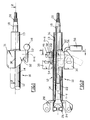
- the steering column assembly 10 illustrated in the figures comprises a steering column body 12 comprising two telescopic tubes or sleeves 13 and 14 capable of sliding relative to one another and in which a shaft is mounted for rotation steering 16 in two parts 18 and 22.
- the first part 18 of the shaft 16 has at its end 20 means for mounting a steering wheel (not shown) while the end 24 of the second part 22 of the steering shaft 16 has means 26 for its connection to the rest of the vehicle steering mechanism (not shown).
- the two parts 18 and 22 are also linked in rotation by grooves (not shown).
- the sleeve 14 carries at its front end, that is to say on the left, considering Figures 1 and 2, a fixing flange 28 allowing its mounting on the structure of the vehicle body.
- the column body 12 is also supported by side flanges 30 which are welded to a column support 31 which is a part having a general U-shaped section whose branches 32 constitute two elastically deformable flanges between which is received the tubular sheath 13.
- a clamping piece 34 which comprises two clamping pads 36 immobilized in longitudinal translation relative to the support 31 and the flanges 30 and which are capable of cooperating with the outer cylindrical surface of the sheath 13 to immobilize the latter in longitudinal translation relative to the sleeve 14 and relative to the structure of the vehicle body.
- Clamping is ensured by mutual approximation of the flanges 32 by means of a clamping mechanism comprising a tie rod 38 which passes through the flanges 32 and of which a first end 40 is equipped with a support pad 42 which bears on the outside on one of the flanges 32.
- the other end 44 of the tie rod 38 comprises a stop member 46 and a shoe 48 which bears against the other flange 32, which are mounted to move longitudinally on the tie rod 38 and between which is a spacer member 50 which, according to a known arrangement, can tilt around an axis XX, illustrated in FIGS. 1, 2 and 3 which is substantially perpendicular to the longitudinal axis YY of the steering column and to the direction of advance of the vehicle.
- the spacer 50 which is illustrated in the locking position in the figures, is connected to a locking control lever 52, one end of which is fixed to the intermediate spacer 50 so as to allow tilting. of the control lever around the XX axis.
- the other end 56 of the control lever 52 is equipped with an inertia mass 58.
- the mass of inertia 58 makes it possible to carry out an automatic unlocking, or release, of the blocking device in the event of an impact or collision of the vehicle when, under the effect of the deceleration which this last, the mass of inertia 58 is driven in forward movement, that is to say from right to left considering Figures 1 and 2 and then automatically causes the control lever 52 to tilt around axis XX towards its release position illustrated in phantom in Figure 2, the steering wheel thus being free to retract forward.
- the length and the position of the lever 52 are determined on the one hand so that the driver can release the locking device by means of a normal force exerted on the handle constituted by the inertia mass 58, the value of this force can be adjusted by tightening the nut 41 on the end 40 of the tie rod 38.
- the weight of the inertia mass 58 can be determined precisely so as to cause the automatic release of the locking device at a determined instant after impact, this instant being in particular a function of the average deceleration curve of the vehicle and of the occupant trajectory as shown by impact tests carried out by the manufacturers of motor vehicles.
- the locking mechanism of the two telescopic elements of the column just described is of a type commonly used to lock it in position, in order to determine the position of the steering wheel inside the passenger compartment, and its release for adjustment of this position.
- the control lever 52 is maneuvered by the driver and is located so as to be accessible to him.
- the mechanism that has just been described therefore makes it easy to perform the two functions, it suffices to add a device (pin, pin, etc.), independent of the blocking system and capable of disappearing in the event of an impact. , intended to limit the adjustment stroke of the steering wheel in order to maintain a sufficient stroke length to allow the column to retract in the event of an impact.
- the locking device which has been illustrated and described with reference to the figures is of the clamping type of a tube, but the invention is not limited to this design of the locking device.
- the inertia mass 58 has been illustrated as fixed directly to the end 56 of the control lever 52 but it could, as a variant, be constituted for example by a counterweight circulating in a tube and connected to the lever by a cable aimed to pull it in the direction of the release of the device.
- an inertial mechanism transmits an order to release a control member, for example of the electromagnetic type which, in normal use, immobilizes two components of the column body longitudinally of management.
Landscapes
- Engineering & Computer Science (AREA)
- Chemical & Material Sciences (AREA)
- Combustion & Propulsion (AREA)
- Transportation (AREA)
- Mechanical Engineering (AREA)
- Steering Controls (AREA)
Applications Claiming Priority (2)
| Application Number | Priority Date | Filing Date | Title |
|---|---|---|---|
| FR9301796A FR2701682B1 (fr) | 1993-02-17 | 1993-02-17 | Ensemble de colonne de direction escamotable en cas de choc. |
| FR9301796 | 1993-02-17 |
Publications (2)
| Publication Number | Publication Date |
|---|---|
| EP0611690A1 true EP0611690A1 (de) | 1994-08-24 |
| EP0611690B1 EP0611690B1 (de) | 1997-05-02 |
Family
ID=9444147
Family Applications (1)
| Application Number | Title | Priority Date | Filing Date |
|---|---|---|---|
| EP19940400169 Expired - Lifetime EP0611690B1 (de) | 1993-02-17 | 1994-01-26 | Bei Stoss einfahrbare Lenksäuleneinrichtung |
Country Status (3)
| Country | Link |
|---|---|
| EP (1) | EP0611690B1 (de) |
| DE (1) | DE69402891T2 (de) |
| FR (1) | FR2701682B1 (de) |
Cited By (8)
| Publication number | Priority date | Publication date | Assignee | Title |
|---|---|---|---|---|
| EP0805092A1 (de) * | 1996-05-03 | 1997-11-05 | Lemforder Nacam S.A. | Bei einem Stoss aktive Rückzueinrichtung einer Kraftfahrzeug-Lenksäule |
| FR2784343A1 (fr) * | 1998-10-07 | 2000-04-14 | Ecia Equip Composants Ind Auto | Ensemble de colonne de direction reglable en position, par exemple pour vehicule automobile |
| GB2368894A (en) * | 2000-11-14 | 2002-05-15 | Nastech Europ Ltd | A steering column assembly for a vehicle |
| EP1223096A1 (de) * | 2001-01-11 | 2002-07-17 | FUJI KIKO Co., Ltd. | Lenksäuleneinheit für ein Fahrzeug |
| WO2006011378A1 (ja) | 2004-07-27 | 2006-02-02 | Nsk Ltd. | ステアリングコラム装置 |
| US7204516B2 (en) | 2004-06-02 | 2007-04-17 | Delphi Technologies, Inc. | Telescope wedge locking mechanism |
| GB2463137A (en) * | 2008-09-06 | 2010-03-10 | Trw Ltd | Steering column assembly |
| WO2015185892A1 (en) * | 2014-06-02 | 2015-12-10 | Trw Limited | A steering column assembly |
Families Citing this family (4)
| Publication number | Priority date | Publication date | Assignee | Title |
|---|---|---|---|---|
| EP1125820B2 (de) † | 2000-02-15 | 2012-07-11 | Nsk Ltd | Lenkung für ein Automobil |
| DE10022091A1 (de) * | 2000-05-08 | 2001-11-15 | Willi Elbe Gelenkwellen Gmbh & | Simulationsvorrichtung |
| DE102005034952B3 (de) * | 2005-07-22 | 2007-02-22 | Thyssenkrupp Automotive Ag | Verstellbare Lenksäule für ein Kraftfahrzeug |
| DE112008003076B4 (de) * | 2007-11-13 | 2019-06-19 | Nsk Ltd. | Lenkvorrichtung |
Citations (4)
| Publication number | Priority date | Publication date | Assignee | Title |
|---|---|---|---|---|
| EP0289133A2 (de) * | 1987-03-27 | 1988-11-02 | Fuji Kiko Company Limited | Ausbildung einer teleskopischen Lenkung für ein Fahrzeug |
| DE3723376A1 (de) * | 1987-07-15 | 1989-01-26 | Bayerische Motoren Werke Ag | Lenksaeule fuer kraftfahrzeuge |
| US4970910A (en) * | 1989-11-13 | 1990-11-20 | General Motors Corporation | Steering column with tilt-adjustable steering wheel |
| DE4030841A1 (de) * | 1990-09-30 | 1992-04-02 | Bayerische Motoren Werke Ag | Lenksaeule fuer kraftfahrzeuge |
-
1993
- 1993-02-17 FR FR9301796A patent/FR2701682B1/fr not_active Expired - Fee Related
-
1994
- 1994-01-26 DE DE1994602891 patent/DE69402891T2/de not_active Expired - Fee Related
- 1994-01-26 EP EP19940400169 patent/EP0611690B1/de not_active Expired - Lifetime
Patent Citations (4)
| Publication number | Priority date | Publication date | Assignee | Title |
|---|---|---|---|---|
| EP0289133A2 (de) * | 1987-03-27 | 1988-11-02 | Fuji Kiko Company Limited | Ausbildung einer teleskopischen Lenkung für ein Fahrzeug |
| DE3723376A1 (de) * | 1987-07-15 | 1989-01-26 | Bayerische Motoren Werke Ag | Lenksaeule fuer kraftfahrzeuge |
| US4970910A (en) * | 1989-11-13 | 1990-11-20 | General Motors Corporation | Steering column with tilt-adjustable steering wheel |
| DE4030841A1 (de) * | 1990-09-30 | 1992-04-02 | Bayerische Motoren Werke Ag | Lenksaeule fuer kraftfahrzeuge |
Cited By (18)
| Publication number | Priority date | Publication date | Assignee | Title |
|---|---|---|---|---|
| FR2748251A1 (fr) * | 1996-05-03 | 1997-11-07 | Lemforder Nacam Sa | Dispositif de retraction actif, lors d'un choc, d'une colonne de direction de vehicule automobile |
| EP0805092A1 (de) * | 1996-05-03 | 1997-11-05 | Lemforder Nacam S.A. | Bei einem Stoss aktive Rückzueinrichtung einer Kraftfahrzeug-Lenksäule |
| FR2784343A1 (fr) * | 1998-10-07 | 2000-04-14 | Ecia Equip Composants Ind Auto | Ensemble de colonne de direction reglable en position, par exemple pour vehicule automobile |
| GB2368894B (en) * | 2000-11-14 | 2005-07-20 | Nastech Europ Ltd | Steering column assembly for a vehicle |
| GB2368894A (en) * | 2000-11-14 | 2002-05-15 | Nastech Europ Ltd | A steering column assembly for a vehicle |
| US7051612B2 (en) | 2000-11-14 | 2006-05-30 | Nsk Steering Systemes Europe Limited | Steering column assembly for a vehicle |
| EP1223096A1 (de) * | 2001-01-11 | 2002-07-17 | FUJI KIKO Co., Ltd. | Lenksäuleneinheit für ein Fahrzeug |
| US6623036B2 (en) | 2001-01-11 | 2003-09-23 | Fuji Kiko Co., Ltd. | Steering column assembly for a vehicle |
| US7204516B2 (en) | 2004-06-02 | 2007-04-17 | Delphi Technologies, Inc. | Telescope wedge locking mechanism |
| WO2006011378A1 (ja) | 2004-07-27 | 2006-02-02 | Nsk Ltd. | ステアリングコラム装置 |
| EP1790550A4 (de) * | 2004-07-27 | 2007-12-26 | Nsk Ltd | Lenksäulenvorrichtung |
| CN100469638C (zh) * | 2004-07-27 | 2009-03-18 | 日本精工株式会社 | 转向柱装置 |
| CN101200195B (zh) * | 2004-07-27 | 2010-10-27 | 日本精工株式会社 | 转向柱装置 |
| US8505407B2 (en) | 2004-07-27 | 2013-08-13 | Nsk Ltd. | Steering column device |
| GB2463137A (en) * | 2008-09-06 | 2010-03-10 | Trw Ltd | Steering column assembly |
| GB2463137B (en) * | 2008-09-06 | 2012-07-25 | Trw Ltd | Steering column assembly |
| WO2015185892A1 (en) * | 2014-06-02 | 2015-12-10 | Trw Limited | A steering column assembly |
| US10137923B2 (en) | 2014-06-02 | 2018-11-27 | Trw Limited | Steering column assembly |
Also Published As
| Publication number | Publication date |
|---|---|
| EP0611690B1 (de) | 1997-05-02 |
| FR2701682B1 (fr) | 1995-05-24 |
| FR2701682A1 (fr) | 1994-08-26 |
| DE69402891D1 (de) | 1997-06-05 |
| DE69402891T2 (de) | 1997-10-02 |
Similar Documents
| Publication | Publication Date | Title |
|---|---|---|
| EP0611690B1 (de) | Bei Stoss einfahrbare Lenksäuleneinrichtung | |
| WO2002044581A1 (fr) | Cylindre de frein a disque avec mecanisme de frein de parc | |
| EP0662413B1 (de) | Energieabsorbierende Einrichtung für eine Kraftfahrzeuglenksäule | |
| FR2590533A1 (fr) | Dispositif antivol de blocage de direction pour vehicules automobiles | |
| EP0849141A1 (de) | Axial zurückziehbare Lenksäuleneinheit, insbesondere für ein Kraftfahrzeug | |
| EP0634314B1 (de) | Im Fall eines Stosses axial zurückziehbare Lenksäuleneinheit, insbesondere für ein Kraftfahrzeug | |
| FR2747079A1 (fr) | Siege de vehicule, deplacable vers l'avant pour acceder a un espace arriere | |
| EP0466534B1 (de) | Handbremshebel, insbesondere für Kraftfahrzeuge | |
| FR3057532A1 (fr) | Volant pour vehicule automobile autonome. | |
| FR2768203A1 (fr) | Securite d'engagement a basculement d'un dispositif de maintien en position d'un systeme de serrage de deux elements | |
| FR2687628A1 (fr) | Ensemble de colonne de direction reglable en position pour vehicule automobile. | |
| EP0795435B1 (de) | Einstellbare Rücklehne für Fahrzeugsitz | |
| FR2715368A1 (fr) | Poste de conduite de véhicule automobile. | |
| FR2809368A1 (fr) | Colonne de direction a manchon antivol, ensemble comprenant une telle colonne et une serrure, et vehicule automobile correspondant | |
| FR2779698A1 (fr) | Dispositif de colonne de direction reglable pour vehicule, notamment automobile | |
| FR2748438A1 (fr) | Dispositif de commande a main d'un frein de stationnement de vehicule automobile et agencement de ce dispositif dans le vehicule | |
| EP0978671A1 (de) | Mit dem Getriebeschalthebel kombinierte Steuervorrichtung für eine Parkbremse | |
| FR3098265A1 (fr) | Dispositif de commande de frein de parking | |
| EP1547892B1 (de) | Elektrische Betätigungsvorrichtung für eine Feststellbremse | |
| FR2832683A1 (fr) | Ensemble de direction a colonne de direction reglable en position et vehicule automobile correspondant | |
| WO2024156558A1 (fr) | Colonne de direction comportant un système mutualisé de réglage par un utilisateur et d'absorption d'énergie en cas d'accident | |
| EP1700073B1 (de) | Kraftfahrzeugbremse und verfahren zur montage einer solchen bremse | |
| FR2753947A1 (fr) | Dispositif de commande a main d'un frein de stationnement de vehicule automobile | |
| FR3141670A1 (fr) | Colonne de direction munie d’un verrou | |
| FR2904991A1 (fr) | Dispositif a blocage selectif pour un frein a disque integre a un frein a tambour |
Legal Events
| Date | Code | Title | Description |
|---|---|---|---|
| PUAI | Public reference made under article 153(3) epc to a published international application that has entered the european phase |
Free format text: ORIGINAL CODE: 0009012 |
|
| AK | Designated contracting states |
Kind code of ref document: A1 Designated state(s): DE GB IT |
|
| 17P | Request for examination filed |
Effective date: 19950124 |
|
| 17Q | First examination report despatched |
Effective date: 19951002 |
|
| GRAG | Despatch of communication of intention to grant |
Free format text: ORIGINAL CODE: EPIDOS AGRA |
|
| GRAH | Despatch of communication of intention to grant a patent |
Free format text: ORIGINAL CODE: EPIDOS IGRA |
|
| GRAH | Despatch of communication of intention to grant a patent |
Free format text: ORIGINAL CODE: EPIDOS IGRA |
|
| GRAA | (expected) grant |
Free format text: ORIGINAL CODE: 0009210 |
|
| AK | Designated contracting states |
Kind code of ref document: B1 Designated state(s): DE GB IT |
|
| ITF | It: translation for a ep patent filed | ||
| REF | Corresponds to: |
Ref document number: 69402891 Country of ref document: DE Date of ref document: 19970605 |
|
| GBT | Gb: translation of ep patent filed (gb section 77(6)(a)/1977) |
Effective date: 19970714 |
|
| PLBE | No opposition filed within time limit |
Free format text: ORIGINAL CODE: 0009261 |
|
| STAA | Information on the status of an ep patent application or granted ep patent |
Free format text: STATUS: NO OPPOSITION FILED WITHIN TIME LIMIT |
|
| 26N | No opposition filed | ||
| PGFP | Annual fee paid to national office [announced via postgrant information from national office to epo] |
Ref country code: DE Payment date: 19990107 Year of fee payment: 6 |
|
| PGFP | Annual fee paid to national office [announced via postgrant information from national office to epo] |
Ref country code: GB Payment date: 19990119 Year of fee payment: 6 |
|
| PG25 | Lapsed in a contracting state [announced via postgrant information from national office to epo] |
Ref country code: GB Free format text: LAPSE BECAUSE OF NON-PAYMENT OF DUE FEES Effective date: 20000126 |
|
| GBPC | Gb: european patent ceased through non-payment of renewal fee |
Effective date: 20000126 |
|
| PG25 | Lapsed in a contracting state [announced via postgrant information from national office to epo] |
Ref country code: DE Free format text: LAPSE BECAUSE OF NON-PAYMENT OF DUE FEES Effective date: 20001101 |
|
| PG25 | Lapsed in a contracting state [announced via postgrant information from national office to epo] |
Ref country code: IT Free format text: LAPSE BECAUSE OF NON-PAYMENT OF DUE FEES;WARNING: LAPSES OF ITALIAN PATENTS WITH EFFECTIVE DATE BEFORE 2007 MAY HAVE OCCURRED AT ANY TIME BEFORE 2007. THE CORRECT EFFECTIVE DATE MAY BE DIFFERENT FROM THE ONE RECORDED. Effective date: 20050126 |