EP0612096A1 - Entraînement pour anode tournante - Google Patents
Entraînement pour anode tournante Download PDFInfo
- Publication number
- EP0612096A1 EP0612096A1 EP94200323A EP94200323A EP0612096A1 EP 0612096 A1 EP0612096 A1 EP 0612096A1 EP 94200323 A EP94200323 A EP 94200323A EP 94200323 A EP94200323 A EP 94200323A EP 0612096 A1 EP0612096 A1 EP 0612096A1
- Authority
- EP
- European Patent Office
- Prior art keywords
- rotor
- drive device
- stator
- motor
- drive
- Prior art date
- Legal status (The legal status is an assumption and is not a legal conclusion. Google has not performed a legal analysis and makes no representation as to the accuracy of the status listed.)
- Granted
Links
- 230000005540 biological transmission Effects 0.000 claims abstract description 8
- XEEYBQQBJWHFJM-UHFFFAOYSA-N Iron Chemical compound [Fe] XEEYBQQBJWHFJM-UHFFFAOYSA-N 0.000 claims description 10
- RYGMFSIKBFXOCR-UHFFFAOYSA-N Copper Chemical compound [Cu] RYGMFSIKBFXOCR-UHFFFAOYSA-N 0.000 claims description 7
- 229910052802 copper Inorganic materials 0.000 claims description 7
- 239000010949 copper Substances 0.000 claims description 7
- 229910052742 iron Inorganic materials 0.000 claims description 5
- 239000000919 ceramic Substances 0.000 claims description 3
- 239000011521 glass Substances 0.000 claims description 3
- 229910018487 Ni—Cr Inorganic materials 0.000 claims description 2
- 229910000831 Steel Inorganic materials 0.000 claims description 2
- VNNRSPGTAMTISX-UHFFFAOYSA-N chromium nickel Chemical compound [Cr].[Ni] VNNRSPGTAMTISX-UHFFFAOYSA-N 0.000 claims description 2
- 239000000110 cooling liquid Substances 0.000 claims description 2
- 239000010959 steel Substances 0.000 claims description 2
- XAGFODPZIPBFFR-UHFFFAOYSA-N aluminium Chemical compound [Al] XAGFODPZIPBFFR-UHFFFAOYSA-N 0.000 claims 3
- 229910052782 aluminium Inorganic materials 0.000 claims 2
- 229910052751 metal Inorganic materials 0.000 description 3
- 239000002184 metal Substances 0.000 description 3
- 238000000926 separation method Methods 0.000 description 3
- 230000005672 electromagnetic field Effects 0.000 description 2
- 238000002955 isolation Methods 0.000 description 2
- 239000000463 material Substances 0.000 description 2
- 230000009467 reduction Effects 0.000 description 2
- 238000004804 winding Methods 0.000 description 2
- 230000002411 adverse Effects 0.000 description 1
- 239000002826 coolant Substances 0.000 description 1
- 238000001816 cooling Methods 0.000 description 1
- 238000005553 drilling Methods 0.000 description 1
- 239000012212 insulator Substances 0.000 description 1
- 238000003475 lamination Methods 0.000 description 1
- 230000007257 malfunction Effects 0.000 description 1
- 229910001220 stainless steel Inorganic materials 0.000 description 1
- 239000010935 stainless steel Substances 0.000 description 1
Images

Classifications
-
- H—ELECTRICITY
- H05—ELECTRIC TECHNIQUES NOT OTHERWISE PROVIDED FOR
- H05G—X-RAY TECHNIQUE
- H05G1/00—X-ray apparatus involving X-ray tubes; Circuits therefor
- H05G1/08—Electrical details
- H05G1/66—Circuit arrangements for X-ray tubes with target movable relatively to the anode
-
- H—ELECTRICITY
- H01—ELECTRIC ELEMENTS
- H01J—ELECTRIC DISCHARGE TUBES OR DISCHARGE LAMPS
- H01J35/00—X-ray tubes
- H01J35/02—Details
- H01J35/04—Electrodes ; Mutual position thereof; Constructional adaptations therefor
- H01J35/08—Anodes; Anti cathodes
- H01J35/10—Rotary anodes; Arrangements for rotating anodes; Cooling rotary anodes
- H01J35/101—Arrangements for rotating anodes, e.g. supporting means, means for greasing, means for sealing the axle or means for shielding or protecting the driving
- H01J35/1017—Bearings for rotating anodes
- H01J35/1024—Rolling bearings
Definitions
- the invention relates to a drive device for the rotating anode of an X-ray tube with a drive motor with stator and rotor, which are operated at anode potential, a rotor shaft driving the rotating anode.
- the object is achieved in that the rotor of the drive motor is designed as an external rotor and the motor is fed by means of a potential-isolating transmission device.
- a further substantial reduction in the volume of the motor can be achieved in that the rotor as Outrunner is realized. Since the torque of the motor is essentially determined by the bore area, the total volume of the motor is determined by the motor parts lying outside the bore area at the desired torque. A stator lying outside the bore area is now of substantially larger size than a rotor lying outside the bore area, in particular if, according to a preferred embodiment of the invention, the rotor consists of one or more concentric metal cylinders.
- the external rotor also has the advantage of a higher moment of inertia compared to an internal rotor, so that in the event of malfunctions in the electronics that feed the motor, e.g. due to high electromagnetic fields, as are typical in X-ray tubes, smaller speed fluctuations will occur. A speed control can then be dispensed with or can be carried out more simply.
- the external rotor shields the motor's electromagnetic field better against the electron and X-ray beam than with an external stator. This is especially the case if, according to a further embodiment of the invention, the rotor length is greater than the laminated core length of the stator, but less than the total length of the stator. The torque is additionally increased by this rotor arrangement.
- the stator interior is drilled through to allow the introduction of cooling liquid, for example oil. Drilling the inside of the stator does not adversely affect the motor properties. The However, coolant can be transported to the desired locations.
- cooling liquid for example oil
- the rotor cylinder consists of copper.
- the external rotor also has such small dimensions that there are no strength problems at high speeds (for example between 3000 rpm and 20,000 rpm) in the rotor designed as a copper cylinder .
- a rotating anode drive can be realized which has a power factor of 0.4 to 0.5 and an efficiency of 40% to 60%. This leads to significant cost reductions in the motor's power supply and in the cooling device of the X-ray tube.
- the drive motor is supplied via an isolating transformer arrangement or via a potential-isolating DC / DC converter.
- the drive of the drive motor is guaranteed by the potential isolation by means of an isolating transformer arrangement or a potential-isolating DC / DC converter.
- volume must be made available for the isolating transformer and DC / DC converter. Due to the spatial separation of motor and electrical isolation, a lower total volume is achieved and this total volume can be more skillfully distributed throughout the device.
- the rotor is vacuum-separated from the stator by means of a non-magnetic separating layer which also supports the stator laminated core, the separating layer consisting for example of nickel-chromium steel, ceramic or glass.
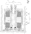
- the rotor 5b of the drive motor 5 is located inside the vacuum chamber 3 .
- the separation from the vacuum chamber 3 is realized in the gap of the motor 5 by the separating layer 4, which can be made, for example, of stainless steel, ceramic or glass.
- This separating layer 4 also serves to receive the stationary stator laminate 5d.
- the stator winding 5c is inserted into the slots of this stator lamination stack 5d.
- Stator winding 5c and stator laminated core 5d form the stator 5a of the drive motor 5.
- the rotor 5b consists of two different materials, a copper cylinder 5e and an iron cylinder 5f surrounding it.
- the drive motor 5 drives the rotating anode 7 via a shaft 6.
- the bearing 7a of the shaft 6 is designed as a ball bearing, but can also be a sliding or a spiral groove bearing.
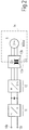
- the motor supply takes place via electrically isolating transmission devices according to FIG. 2 or 3.
- the electrically isolating transmission device according to FIG. 2 consists of a rectifier 11 connected to mains terminals 10a and 10b, an adjoining inverter 12 and an isolating transformer device 13 with the isolating transformer coils 13a and 13b.
- a frame 14 indicates that the coil 13b and the motor 5 are in the high-voltage region of the X-ray tube.
- the part of the inverter on the AC side, as well as the coils 13a and 13b and the motor 5 are of three-phase design.
- FIG. 3 shows another variant of the transmission device.
- an alternating voltage is supplied to the rectifier 11 via the terminals 10a and 10b, which converts the supplied alternating current into a direct current and forms one DC / DC converter 15 feeds.
- the DC / DC converter 15 has an inverter part 15a, a rectifier part 15b and an isolating transformer part 15c.
- the isolating transformer part 15c has two coils 15d and 15e.
- the rectifier part 15b supplies a DC voltage to an inverter 12, which converts the DC voltage supplied to it into a three-phase AC voltage system and outputs it to the motor 5.
- the high-voltage region, outlined by line 14, coil 15e and rectifier part 15b of DC / DC converter 15 includes inverter 12 and motor 5.
Landscapes
- X-Ray Techniques (AREA)
- Connection Of Motors, Electrical Generators, Mechanical Devices, And The Like (AREA)
Applications Claiming Priority (2)
| Application Number | Priority Date | Filing Date | Title |
|---|---|---|---|
| DE4304760A DE4304760A1 (de) | 1993-02-17 | 1993-02-17 | Antriebsvorrichtung für eine Drehanode |
| DE4304760 | 1993-02-17 |
Publications (2)
| Publication Number | Publication Date |
|---|---|
| EP0612096A1 true EP0612096A1 (fr) | 1994-08-24 |
| EP0612096B1 EP0612096B1 (fr) | 1999-05-06 |
Family
ID=6480653
Family Applications (1)
| Application Number | Title | Priority Date | Filing Date |
|---|---|---|---|
| EP94200323A Expired - Lifetime EP0612096B1 (fr) | 1993-02-17 | 1994-02-10 | Entraínement pour anode tournante |
Country Status (4)
| Country | Link |
|---|---|
| US (1) | US5490198A (fr) |
| EP (1) | EP0612096B1 (fr) |
| JP (1) | JP3696263B2 (fr) |
| DE (2) | DE4304760A1 (fr) |
Families Citing this family (11)
| Publication number | Priority date | Publication date | Assignee | Title |
|---|---|---|---|---|
| DE19752114A1 (de) * | 1997-11-25 | 1999-05-27 | Philips Patentverwaltung | Antriebsvorrichtung für eine Röntgen-Drehanode sowie Verfahren zur Steuerung der Antriebsvorrichtung |
| US6212753B1 (en) * | 1997-11-25 | 2001-04-10 | General Electric Company | Complaint joint for interfacing dissimilar metals in X-ray tubes |
| US6281610B1 (en) | 1999-06-29 | 2001-08-28 | General Electric Company | Slip ring brush assembly and method |
| US6198803B1 (en) | 1999-08-20 | 2001-03-06 | General Electric Company | Bearing assembly including rotating element and magnetic bearings |
| DE19945414C2 (de) * | 1999-09-22 | 2001-07-19 | Siemens Ag | Rotor für eine Drehanode einer Röntgenröhre |
| US6542577B1 (en) | 2000-08-18 | 2003-04-01 | Koninklijke Philips Electronics, N.V. | Hermetically sealed stator cord for x-ray tube applications |
| DE102009022916B4 (de) * | 2009-05-27 | 2011-05-19 | Dst Dauermagnet-System Technik Gmbh | Magnetkupplung sowie Spalttopf für eine Magnetkupplung |
| KR101105967B1 (ko) * | 2009-12-21 | 2012-01-17 | 엘지전자 주식회사 | 컴팩트형 압축기 |
| DE102012212133B3 (de) * | 2012-07-11 | 2013-07-25 | Siemens Aktiengesellschaft | Drehanodenanordnung und Röntgenröhre |
| CN107546089B (zh) * | 2016-08-04 | 2024-05-28 | 上海钧安医疗科技有限公司 | 一种大功率x射线球管 |
| DE102022117847A1 (de) | 2022-07-18 | 2024-01-18 | Dr. Ing. H.C. F. Porsche Aktiengesellschaft | Vorrichtung zum Kühlen einer elektrischen Antriebsmaschine |
Citations (6)
| Publication number | Priority date | Publication date | Assignee | Title |
|---|---|---|---|---|
| US4107535A (en) * | 1975-06-20 | 1978-08-15 | Hitachi, Ltd. | X-ray apparatus utilizing rotary anode type X-ray tubes |
| FR2484698A1 (fr) * | 1980-06-16 | 1981-12-18 | Siemens Ag | Tube a rayons x a anode tournante |
| EP0108336A2 (fr) * | 1982-11-03 | 1984-05-16 | General Electric Company | Dispositif d'alimentation de puissance à haute fréquence pour générateur à rayons X |
| JPS61225745A (ja) * | 1985-03-29 | 1986-10-07 | Shimadzu Corp | 回転陽極x線管 |
| EP0401901A2 (fr) * | 1989-06-03 | 1990-12-12 | Philips Patentverwaltung GmbH | Générateur pour le fonctionnement d'un tube à rayons x à anode tournante |
| US5090048A (en) * | 1991-05-22 | 1992-02-18 | General Electric Company | Shielded enclosure with an isolation transformer |
Family Cites Families (2)
| Publication number | Priority date | Publication date | Assignee | Title |
|---|---|---|---|---|
| FR2399124A1 (fr) * | 1977-07-29 | 1979-02-23 | Radiologie Cie Gle | Tube a rayons x a anode tournante |
| DE2815893A1 (de) * | 1978-04-12 | 1979-10-18 | Siemens Ag | Roentgendiagnostikgenerator mit einem den hochspannungstransformator speisenden wechselrichter |
-
1993
- 1993-02-17 DE DE4304760A patent/DE4304760A1/de not_active Withdrawn
-
1994
- 1994-02-10 EP EP94200323A patent/EP0612096B1/fr not_active Expired - Lifetime
- 1994-02-10 DE DE59408190T patent/DE59408190D1/de not_active Expired - Fee Related
- 1994-02-14 JP JP01730894A patent/JP3696263B2/ja not_active Expired - Fee Related
-
1995
- 1995-04-17 US US08/425,305 patent/US5490198A/en not_active Expired - Lifetime
Patent Citations (6)
| Publication number | Priority date | Publication date | Assignee | Title |
|---|---|---|---|---|
| US4107535A (en) * | 1975-06-20 | 1978-08-15 | Hitachi, Ltd. | X-ray apparatus utilizing rotary anode type X-ray tubes |
| FR2484698A1 (fr) * | 1980-06-16 | 1981-12-18 | Siemens Ag | Tube a rayons x a anode tournante |
| EP0108336A2 (fr) * | 1982-11-03 | 1984-05-16 | General Electric Company | Dispositif d'alimentation de puissance à haute fréquence pour générateur à rayons X |
| JPS61225745A (ja) * | 1985-03-29 | 1986-10-07 | Shimadzu Corp | 回転陽極x線管 |
| EP0401901A2 (fr) * | 1989-06-03 | 1990-12-12 | Philips Patentverwaltung GmbH | Générateur pour le fonctionnement d'un tube à rayons x à anode tournante |
| US5090048A (en) * | 1991-05-22 | 1992-02-18 | General Electric Company | Shielded enclosure with an isolation transformer |
Non-Patent Citations (1)
| Title |
|---|
| PATENT ABSTRACTS OF JAPAN vol. 11, no. 70 (E - 485)<2517> 3 March 1987 (1987-03-03) * |
Also Published As
| Publication number | Publication date |
|---|---|
| DE4304760A1 (de) | 1994-08-18 |
| EP0612096B1 (fr) | 1999-05-06 |
| JPH06251734A (ja) | 1994-09-09 |
| DE59408190D1 (de) | 1999-06-10 |
| JP3696263B2 (ja) | 2005-09-14 |
| US5490198A (en) | 1996-02-06 |
Similar Documents
| Publication | Publication Date | Title |
|---|---|---|
| EP3920385B1 (fr) | Machine à excitation électrique et agencement pour une machine à excitation électrique | |
| EP0612096B1 (fr) | Entraínement pour anode tournante | |
| EP3918695B1 (fr) | Entraînement électrique et procédé servant à faire fonctionner l'entraînement électrique | |
| DE4133001C2 (de) | Elektrische Maschine | |
| DE10147073A1 (de) | Elektromotor, insbesondere elektronisch kommutierter Gleichstrommotor | |
| WO1995028720A1 (fr) | Traversee de cables pour appareils a courant alternatif a supraconductivite | |
| EP2846440A1 (fr) | Machine électrique dotée d'un dispositif conducteur de chaleur | |
| WO2022136548A1 (fr) | Transformateur rotatif électrique destiné à la transmission inductive d'énergie | |
| DE3629044A1 (de) | Statische erregervorrichtung fuer eine dynamoelektrische maschine | |
| DE102010063734B4 (de) | Elektrische Maschine | |
| WO2005091468A1 (fr) | Machine electrodynamique refroidie comportant une gaine | |
| DE102013207806A1 (de) | Elektrische Maschine | |
| EP3394960B1 (fr) | Pompe centrifuge, notamment pompe de circulation | |
| DE19948145C1 (de) | Vermeidung von umrichterbedingten Lagerschäden bei Drehstrommotoren | |
| DE2953100C1 (de) | Hochspannungs-Transformations- und Gleichrichtereinrichtung | |
| EP2892133A2 (fr) | Moteurs à induction pour fréquence variable à fort glissement | |
| EP0131061B1 (fr) | Pompe à induction linéaire pour déplacer des fluides électriquement conducteurs | |
| EP3723247A1 (fr) | Stator pour une machine électrique dotée d'un condensateur | |
| EP0780876A2 (fr) | Système d'entraînnement pour anode tournante de tube à rayons X | |
| EP1881581A2 (fr) | Moteur asynchrone triphasé à convertisseur de fréquence | |
| EP1708342A2 (fr) | Excitateur rotatif de grands courants | |
| DE10045094A1 (de) | Permanentmagneterregte Synchronmaschine für den Einsatz in explosionsgefährdeten Bereichen | |
| DE3509906A1 (de) | Dauermagnetmotor | |
| DE202016003559U1 (de) | Vakuumpumpe mit hybridem Synchron-Reluktanzmotor | |
| DE102024208129A1 (de) | Gleichrichtereinheit für eine Rotorvorrichtung, Rotorvorrichtung und fremderregte Synchronmaschine |
Legal Events
| Date | Code | Title | Description |
|---|---|---|---|
| PUAI | Public reference made under article 153(3) epc to a published international application that has entered the european phase |
Free format text: ORIGINAL CODE: 0009012 |
|
| AK | Designated contracting states |
Kind code of ref document: A1 Designated state(s): DE FR GB IT |
|
| 17P | Request for examination filed |
Effective date: 19950224 |
|
| 17Q | First examination report despatched |
Effective date: 19951128 |
|
| GRAG | Despatch of communication of intention to grant |
Free format text: ORIGINAL CODE: EPIDOS AGRA |
|
| GRAG | Despatch of communication of intention to grant |
Free format text: ORIGINAL CODE: EPIDOS AGRA |
|
| GRAH | Despatch of communication of intention to grant a patent |
Free format text: ORIGINAL CODE: EPIDOS IGRA |
|
| RAP3 | Party data changed (applicant data changed or rights of an application transferred) |
Owner name: KONINKLIJKE PHILIPS ELECTRONICS N.V. Owner name: PHILIPS PATENTVERWALTUNG GMBH |
|
| GRAH | Despatch of communication of intention to grant a patent |
Free format text: ORIGINAL CODE: EPIDOS IGRA |
|
| GRAA | (expected) grant |
Free format text: ORIGINAL CODE: 0009210 |
|
| AK | Designated contracting states |
Kind code of ref document: B1 Designated state(s): DE FR GB IT |
|
| PG25 | Lapsed in a contracting state [announced via postgrant information from national office to epo] |
Ref country code: IT Free format text: LAPSE BECAUSE OF FAILURE TO SUBMIT A TRANSLATION OF THE DESCRIPTION OR TO PAY THE FEE WITHIN THE PRESCRIBED TIME-LIMIT;WARNING: LAPSES OF ITALIAN PATENTS WITH EFFECTIVE DATE BEFORE 2007 MAY HAVE OCCURRED AT ANY TIME BEFORE 2007. THE CORRECT EFFECTIVE DATE MAY BE DIFFERENT FROM THE ONE RECORDED. Effective date: 19990506 Ref country code: GB Free format text: LAPSE BECAUSE OF FAILURE TO SUBMIT A TRANSLATION OF THE DESCRIPTION OR TO PAY THE FEE WITHIN THE PRESCRIBED TIME-LIMIT Effective date: 19990506 |
|
| REF | Corresponds to: |
Ref document number: 59408190 Country of ref document: DE Date of ref document: 19990610 |
|
| ET | Fr: translation filed | ||
| GBV | Gb: ep patent (uk) treated as always having been void in accordance with gb section 77(7)/1977 [no translation filed] |
Effective date: 19990506 |
|
| RAP4 | Party data changed (patent owner data changed or rights of a patent transferred) |
Owner name: KONINKLIJKE PHILIPS ELECTRONICS N.V. Owner name: PHILIPS CORPORATE INTELLECTUAL PROPERTY GMBH |
|
| PLBE | No opposition filed within time limit |
Free format text: ORIGINAL CODE: 0009261 |
|
| STAA | Information on the status of an ep patent application or granted ep patent |
Free format text: STATUS: NO OPPOSITION FILED WITHIN TIME LIMIT |
|
| 26N | No opposition filed | ||
| PGFP | Annual fee paid to national office [announced via postgrant information from national office to epo] |
Ref country code: DE Payment date: 20070410 Year of fee payment: 14 |
|
| PGFP | Annual fee paid to national office [announced via postgrant information from national office to epo] |
Ref country code: FR Payment date: 20070226 Year of fee payment: 14 |
|
| REG | Reference to a national code |
Ref country code: FR Ref legal event code: ST Effective date: 20081031 |
|
| PG25 | Lapsed in a contracting state [announced via postgrant information from national office to epo] |
Ref country code: DE Free format text: LAPSE BECAUSE OF NON-PAYMENT OF DUE FEES Effective date: 20080902 |
|
| PG25 | Lapsed in a contracting state [announced via postgrant information from national office to epo] |
Ref country code: FR Free format text: LAPSE BECAUSE OF NON-PAYMENT OF DUE FEES Effective date: 20080229 |