EP0612155B1 - Kodierverfahren, Kodierer und Dekodierer für ein Digitalsignal - Google Patents
Kodierverfahren, Kodierer und Dekodierer für ein Digitalsignal Download PDFInfo
- Publication number
- EP0612155B1 EP0612155B1 EP94100597A EP94100597A EP0612155B1 EP 0612155 B1 EP0612155 B1 EP 0612155B1 EP 94100597 A EP94100597 A EP 94100597A EP 94100597 A EP94100597 A EP 94100597A EP 0612155 B1 EP0612155 B1 EP 0612155B1
- Authority
- EP
- European Patent Office
- Prior art keywords
- quantization accuracy
- accuracy information
- coder
- information
- quantization
- Prior art date
- Legal status (The legal status is an assumption and is not a legal conclusion. Google has not performed a legal analysis and makes no representation as to the accuracy of the status listed.)
- Expired - Lifetime
Links
Images



Classifications
-
- H—ELECTRICITY
- H03—ELECTRONIC CIRCUITRY
- H03M—CODING; DECODING; CODE CONVERSION IN GENERAL
- H03M7/00—Conversion of a code where information is represented by a given sequence or number of digits to a code where the same, similar or subset of information is represented by a different sequence or number of digits
Definitions
- This invention relates to a coding method for a digital signal applied to an encoder/decoder system which is adapted to carry out coding of an input signal such as a digital audio signal, etc. to transmit or receive a coded signal through a communication medium, or record or reproduce it through a recording medium to send such coded signal to a decoder to decode it to obtain a reproduced signal, a coder using such a coding method, a decoder for decoding an information signal coded by such a coding method, and a recording medium on which an information signal coded by such a coding method is recorded.
- SBC subband coding
- a frequency band division system including no coding processing using blocks (signal sample blocks) in which an audio signal, etc. on the time base is divided into signal components in plural frequency bands without dividing such a signal into blocks (signal sample blocks) to encode them
- a frequency band division system including coding processing using blocks (signal sample blocks), which is so called transform coding, adapted to transform a signal on the time base to a signal on the frequency base (spectrum transform) to divide it into signal components in plural frequency bands to encode such signal components every respective bands; and the like.
- spectrum transform processing e.g., there is such a spectrum transform processing to divide an input audio signal into blocks (signal sample blocks) every predetermined unit time (frame) to carry out, every block, Fast Fourier Transform (FFT), Discrete Cosine Transform (DCT), Modified DCT (MDCT), etc. to thereby transform signal components on the time base to signal components on the frequency base.
- FFT Fast Fourier Transform
- DCT Discrete Cosine Transform
- MDCT Modified DCT
- MDCT is described in ICASSP 1987, Subband/Transform Coding Using Filter Bank Designs Based on Time Domain Aliasing Cancellation, J.P. Princen, A. B. Bradley, Univ. of Surrey Royal Melbourne Inst. of Tech.
- a frequency division width for quantizing respective frequency components divided into frequency bands there is carried out a band division in which, e.g., the hearing sense characteristic of the human being is taken into consideration. Namely, there are instances where an audio signal is divided into signal components in plural bands (e.g., 25 bands) having band widths adapted to become broader as the frequency shifts to a higher frequency band side, which are generally called critical bands. Further, in encoding data in the respective bands at this time, coding by a predetermined bit allocation is carried out in the respective bands, or coding by an adaptive bit allocation is carried out in the respective bands.
- bit allocation technique For example, in encoding coefficient data obtained after they have undergone the MDCT processing by the above-mentioned bit allocation, coding is carried out by adaptive allocated bit numbers with respect to MDCT coefficient data in the respective bands obtained by MDCT processing for the respective blocks.
- bit allocation technique the following two techniques are known.
- bit allocation is carried out on the basis of the magnitudes of signals every respective bands.
- the quantizing noise spectrum becomes flat, and the noise energy becomes minimum.
- an actual noise sense is not optimum.
- ICASSP 1980 "The critical band coder - digital encoding of the perceptual requirements of the auditory system", M. A. Kransner V, MIT, there is described a technique in which the hearing sense masking is utilized to thereby obtain necessary signal-to-noise ratios every respective bands to carry out a fixed bit allocation.
- bit allocation information In the system adapted for carrying out the fixed bit allocation, there is no necessity of transmitting bit allocation information from the coder to the decoder. Further, also in the system where bit allocation varies depending upon the frequency distribution of a signal, if normalization is carried out in respective bands to transmit their normalization coefficients to the decoder to have an ability to univocally determine bit allocation from those normalization coefficients, there is no necessity that the bit allocation information is sent to the decoder.
- this invention has been made, and its object is to provide a coding method for a digital signal which can realize more efficient coding while leaving the degree of freedom in the method of bit allocation, a coder using such a coding method, a decoder for decoding an information signal coded by such a coding method, and a recording medium on which an information signal coded by such a coding method is recorded.
- This invention is characterized in that differences between bit allocation information (in general, quantization accuracy information) which can be calculated by the decoder itself and actual bit allocation information are efficiently transmitted or recorded to thereby realize more efficient coding while leaving the degree of freedom in the bit allocation method.
- bit allocation information in general, quantization accuracy information
- transmission of a coded information signal obtained by coding to the decoder includes not only transmission/reception through a communication medium, but also recording/reproduction through a recording medium, or the like.
- the above-mentioned second quantization accuracy information is quantization accuracy difference information obtained by taking differences between quantization accuracy information outputted from quantization accuracy determination means and the first quantization accuracy information.
- the first quantization accuracy information may be fixed quantization accuracy information.
- this first quantization accuracy information may be determined by calculation on the basis of normalization coefficients. Further, in the case of implementing coding to signal components of an input digital signal divided into blocks on the time base, quantization accuracy in any other time block may be used as the first quantization accuracy information. In this case, e.g., an earlier time block may be used as the other time block.
- the above-mentioned quantization accuracy information may be transmitted (transmitted or recorded) after it has undergone variable length coding, or may be transmitted while maintaining the fixed length.
- quantization accuracy information in quantization is determined by first quantization accuracy information having no necessity of being sent (transmitted/received or recorded/reproduced) to the decoder and second quantization accuracy information actually sent to the decoder, quantization accuracy information to be transmitted can be reduced, so more efficient coding can be realized while maintaining the degree of freedom in the method of giving quantization accuracy such as bit allocation method, etc.
- quantization is carried out with a quantization accuracy determined by first quantization accuracy information outputted from the quantization accuracy information generating means and second quantization accuracy information (transmitted/received or recorded/reproduced) sent from the coder to the decoder, it is sufficient to transmit only the second quantization accuracy information as compared to the case where quantization accuracy information for carrying out quantization is directly transmitted. For this reason, the degree of freedom of giving quantization accuracy can be improved by a lesser number of bits. Thus, more efficient coding can be attained while leaving a room for improvement in the method of giving quantization accuracy such as bit allocation, etc. in future.
- Fig. 1 is a block diagram showing a coder for a digital audio signal as an embodiment of this invention.
- an audio input signal S x inputted to input terminal 11 is band-divided into signals S Ba , S Bb , S Bc , S Bd by a band division unit 12.
- the band division unit 12 means for filtering such as QMF, etc. may be used, or means for grouping a spectrum obtained by spectrum transform processing such as MDCT, etc. into spectrum components every bands may be used.
- the widths of respective bands may be uniform, or may be uneven so that they are in correspondence with, e.g., critical band width.
- the band is divided into four bands in the example of Fig. 1, it is clear that the divisional number may be more or less than 4.
- Normalization is implemented to the band-divided signals S Ba , S Bb , S Bc , S Bd by normalization units 13a, 13b, 13c, 13d in respective bands for predetermined time blocks, so they are decomposed (separated) into normalization coefficients K Na , K Nb , K Nc , K Nd and normalized output signals S Na , S Nb , S Nc , S Nd .
- normalization is carried out, for the respective bands, e.g., by the maximum values of absolute values of signal components in those band.
- These normalized output signals S Na , S Nb , S Nc , S Nd are quantized by quantization units 14a, 14b, 14c, 14d on the basis of quantization accuracy information Q a , Q b , Q c , Q d which are respectively outputs from a quantization accuracy determination unit 17, so they are converted to normalized/quantized output signals S Qa , S Qb , S Qc , S Qd .
- quantization accuracy information Q a , Q b , Q c , Q d such quantization bit allocation information to indicate quantization bit numbers in quantizing the respective bands are conceivable in actual sense.
- the quantization accuracy information Q a , Q b , Q c , Q d from the quantization accuracy determination unit 17 are coded into quantization accuracy information Q 2 by a quantization accuracy information coding unit 18.
- a quantization accuracy information coding unit 18 means for generating first quantization accuracy information as described later is provided.
- the normalized/quantized output signals S Qa , S Qb , S Qc , S Qd , the normalization coefficients K Na , K Nb , K Nc , K Nd , and quantization accuracy information Q 2 which are obtained in this way are sequentially outputted as a code train signal S Y by a multiplexer 15, and are then recorded and transmitted.
- quantization accuracy informations Q a , Q b , Q c , Q d from the quantization accuracy determination unit 17 are calculated on the basis of the band-divided signals S Ba , S Bb , S Bc , S Bd .
- information calculated from input signal S x or information calculated on the basis of the normalization coefficients K Na , K Nb , K Nc , K Nd may be employed.
- calculation at the quantization accuracy determination unit 17 can be carried out on the basis of the hearing sense phenomenon such as so called masking effect, etc., since the final quantization accuracy information is sent to the decoder, a hearing sense model used at the decoder may be arbitrarily set.
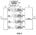
- Fig. 2 is a block diagram showing an embodiment of a decoder corresponding to the coder shown in Fig. 1.
- a signal S Y delivered to input terminal 21 of the decoder is a signal of coded information obtained as the result of the fact that the code train output signal S Y outputted from the coder of Fig. 1 is, e.g., recorded or reproduced through, a recording medium, or transmitted or recorded through a communication medium. Namely, if error, etc. does not take place at the time of transmission (at the time of transmission or reception, or at the time of recording or reproduction), the signal s Y takes the same value as the signal S Y .
- This inputted coded information signal s Y is sent to a demultiplexer 22, at which normalization coefficients k Na , k Nb , k Nc , k Nd respectively corresponding to the normalization coefficients k Na , k Nb , k Nc , k Nd , signals s Qa , s Qb , s Qc , s Qd respectively corresponding to the normalized/quantized output signals S Qa , S Qb , S Qc , S Qd , and quantization accuracy information q 2 corresponding to the quantization accuracy information Q 2 are restored and separated.
- coefficients k Na , k Nb , k Nc , k Nd , signals s Qa , s Qb , s Qc , s Qd and quantization accuracy information q 2 also respectively take the same values of normalization coefficients K Na , K Nb , K Nc , K Nd , normalized/quantized output signals S Qa , S Qb , S Qc , S Qd , and quantization accuracy information Q 2 on the side of the coder if there is no transmission error, etc. as described above.
- the quantization accuracy information q 2 obtained from the demultiplexer 22 is sent to a quantization accuracy information decoding unit 26 of a structure as described later, at which it is converted to quantization accuracy information q a , q b , q c , q d respectively corresponding to the quantization accuracy information Q a , Q b , Q c , Q d .
- quantization accuracy information q a , q b , q c , q d also take the same values as quantization accuracy information Q a , Q b , Q c , Q d on the side of the coder unless there is any transmission error, etc.
- the quantization accuracy information q a , q b , q c , q d , normalization coefficients k Na , k Nb , k Nc , k Nd , and normalized/quantized output signals s Qa , s Qb , s Qc , s Qd in respective bands which are obtained in this way are sent to signal component composing units 23a, 23b, 23c, 23d every respective bands.
- signal components respectively corresponding to the band-divided signals S Ba , S Bb , S Bc , S Bd of Fig. 1 are composed.
- quantization accuracy informations Q a , Q b , Q c , Q d for the bands are coded at the coding unit 18.
- These quantization accuracy information Q a , Q b , Q c , Q d are determined by first quantization accuracy information from the quantization accuracy information generating means provided in the coding unit 18 and information Q 2 coded and sent to the decoder. Accordingly, as compared to the case where quantization accuracy information Q a , Q b , Q c , Q d every respective bands are sent (transmitted or received, or recorded or reproduced) as they are, the number of bits can be reduced. Thus, the entire coding efficiency can be improved.
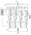
- FIGs. 3 and 4 are block diagrams showing, for making comparison with the embodiments of this invention, examples (comparative examples) of a coder and a decoder where the quantization accuracy information coding unit 18 and quantization accuracy information decoding unit 26 are not respectively provided.
- input terminal 111 is supplied with a digital audio signal S x .
- a band division unit 112 normalization units every respective bands 113a, 113b, 113c, 113d, and quantization units 114a, 114b, 114c, 114d are respectively the same as the band division unit 12, the normalization units 13a, 13b, 13c, 13d, and quantization units 14a, 14b, 14c, 14d of Fig. 1, and their explanation is therefore omitted.
- a quantization accuracy determination unit 117 calculates quantization accuracy information Q a , Q b , Q c , Q d every respective bands on the basis of, e.g., signals S Ba , S Bb , S Bc , S Bd for the respective bands from the band division unit 112.
- the quantization accuracy information Q a , Q b , Q c , Q d for the respective bands, normalization coefficients K Na , K Nb , K Nc , K Nd from the normalization units 113a, 113b, 113c, 113d, normalized/quantized output signals S Qa , S Qb , S Qc , S Qd from the quantization units 114a, 114b, 114c, 114d are sent to a multiplexer 115, and are sequentially taken out from output terminal 116 as a signal S Y of a code train.
- Fig. 4 shows a decoder corresponding to the coder of Fig. 3.
- a signal s Y transmitted as the result of the fact that signal S Y outputted from the coder of Fig. 3 is, e.g., transmitted or received through a communication medium, or recorded or reproduced through a recording medium is inputted.
- quantization accuracy information q a , q b , q c , q d respectively corresponding to the quantization accuracy information Q a , Q b , Q c , Q d are directly obtained.
- signal components s Ba , s Bb , s Bc , s Bd respectively corresponding to the band-divided signal components S Ba , S Bb , S Bc , S Bd of Fig. 3 are composed.
- These signal components are synthesized by a band synthesizing unit 124.
- an audio signal s x corresponding to the input signal S x of Fig. 3 is taken out from output terminal 125.
- FIG. 5 An actual example of the configuration of the quantization accuracy information coding unit 18 used in the above-described coder of Fig. 1 is shown in Fig. 5.
- the quantization accuracy information coding unit 18 shown in Fig. 5 includes a fixed quantization accuracy pattern memory section 33. From this fixed quantization accuracy pattern memory section 33, first quantization accuracy information Q 1a , Q 1b , Q 1c , Q 1d fixedly determined in respective bands are outputted. These first quantization accuracy information Q 1a , Q 1b , Q 1c , Q 1d are sent to subtracters 32a, 32b, 32c, 32d to take differences between quantization accuracy information Q a , Q b , Q c , Q d from the quantization accuracy determination unit 17 of Fig.
- the first quantization accuracy informations Q 1a , Q 1b , Q 1c , Q 1d fixedly determined for the respective bands are set to such values to approximate to actual quantization accuracy information Q a , Q b , Q c , Q d in many cases, there are many instances where the values of the quantization accuracy difference information Q 2a , Q 2b , Q 2c , Q 2d take a value close to zero.
- a scheme is employed to apply coding (so called variable length coding) to difference signals by a shorter bit length when the absolute value of a difference signal is small and by a bit length which becomes longer according as a difference signal becomes greater, quantization accuracy information can be sent by a lesser number of bits.
- quantization accuracy difference information Q 2a , Q 2b , Q 2c , Q 2d can be coded by a fixed number of bits. At this time, if the fixed number of bits is set to a value smaller than the number of bits required when quantization accuracy information Q a , Q b , Q c , Q d every respective bands are directly coded, it is possible to send information relating to quantization accuracy by a lesser quantity of information. In this case, the degree of freedom of quantization accuracy information is limited. However, since quantization accuracy information Q 1a , Q 1b , Q 1c , Q 1d fixedly determined in respective bands are set to information in advance such that they can ensure sound quality to some extent, employment of this method does not constitute great problem.
- Fig. 6 shows the detail of quantization accuracy decoding unit 26 in the decoder shown in Fig. 2. Namely, this figure shows an actual example of the configuration of the quantization accuracy decoding unit 26 corresponding to the quantization accuracy information coding unit 18 of Fig. 5.
- input terminal 41 is supplied with quantization accuracy information q 2 (corresponding to the quantization accuracy information Q 2 ) restored and separated in the demultiplexer 22 of the decoder of Fig. 2.
- This quantization accuracy information q 2 is sent to a decoding section 42, at which quantization accuracy difference information q 2a , q 2b , q 2c , q 2d corresponding to quantization accuracy difference information Q 2a , Q 2b , Q 2c , Q 2d which are second quantization accuracy information for the respective bands are restored.
- quantization accuracy difference informations q 2a , q 2b , q 2c , q 2d are respectively sent to adders 43a, 43b, 43c, 43d, at which they are respectively added, for the respective bands, to quantization accuracy information q 1a , q 1b , q 1c , q 1d outputted from a fixed quantization accuracy pattern memory section 45.
- These fixed quantization accuracy information q 1a , q 1b , q 1c , q 1d for the respective bands corresponds to (are the same values as) first quantization accuracy information Q 1a , Q 1b , Q 1c , Q 1d fixedly determined in respective bands from the fixed quantization accuracy pattern memory section 33 of Fig. 5, respectively.
- Quantization accuracy information q a , q b , q c , q d which are added outputs from adders 43a, 43b, 43c, 43d every bands respectively correspond to quantization accuracy information Q a , Q b , Q c , Q d on the side of the coder, and take the same values as those values (when there is no transmission error, or the like) in a theoretical sense.
- These quantization accuracy information q a , q b , q c , q d are outputted from output terminals 44a, 44b, 44c, 44d, and are sent to the signal components composing units 23a, 23b, 23c, 23d of Fig. 2, respectively.
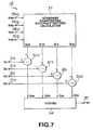
- Fig. 7 is a block diagram showing another actual example of the quantization accuracy information coding unit 18 used in the coder of Fig. 1
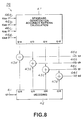
- Fig. 8 is a block diagram showing another example of the quantization accuracy decoding unit 26 in the decoder shown in Fig. 2 wherein there is shown an actual example of the configuration of the quantization accuracy decoding unit corresponding to the quantization accuracy information coding unit of Fig. 7.
- quantization accuracy difference informations which are the second quantization accuracy informations are determined as differences between the quantization accuracy information outputted from the quantization accuracy determination unit and the first quantization accuracy information.
- the first quantization accuracy information outputs of standard quantization accuracy pattern calculation means are used in this embodiment in place of outputs of the fixed quantization accuracy information pattern memory means.
- values of normalization coefficients can be utilized.
- a standard quantization accuracy pattern calculation section 37 is provided in place of the fixed quantization accuracy pattern memory section 33.
- This standard quantization accuracy pattern calculation section 37 is supplied with normalization coefficients K Na , K Nb , K Nc , K Nd every bands of Fig. 1, for example, respectively through input terminals 36a, 36b, 36c, 36d.
- the standard quantization accuracy pattern calculation section 37 determines by calculation the first quantization accuracy information Q 1a , Q 1b , Q 1c , Q 1d by making use of values of these normalization coefficients K Na , K Nb , K Nc , K Nd .
- first quantization accuracy information Q 1a , Q 1b , Q 1c , Q 1d are sent to subtracters 32a, 32b, 32c, 32d to take differences between the quantization accuracy information Q a , Q b , Q c , Q d and the first quantization accuracy information Q 1a , Q 1b , Q 1c , Q 1d to thereby determine quantization accuracy difference information Q 2a , Q 2b , Q 2c , Q 2d which are the second quantization accuracy information.
- a standard quantization accuracy pattern calculation section 47 is provided in place of the fixed quantization accuracy pattern memory section 45. This standard quantization accuracy pattern calculation section 47 calculates the first quantization accuracy information q 1a , q 1b , q 1c , q 1d on the basis of normalization coefficients K Na , K Nb , K Nc , K Nd every bands of Fig.
- an approach is employed to determine by calculation first quantization accuracy information on the basis of normalization coefficients every bands to add them to second quantization accuracy information transmitted to determine quantization accuracy, thereby permitting the values of quantization accuracy difference information which are second quantization accuracy information to concentrate on a value closer to zero.
- more efficient coding can be carried out.
- first quantization accuracy information which serves as reference information for determining quantization accuracy difference information
- quantization accuracy information in any other time block e.g., a block immediate before
- any other time block e.g., a block immediate before
- the configuration is represented by the functional block in the embodiments shown, it is of course that such configuration can be realized by hardware or software.
Landscapes
- Engineering & Computer Science (AREA)
- Theoretical Computer Science (AREA)
- Compression, Expansion, Code Conversion, And Decoders (AREA)
Claims (24)
- Kodierverfahren zum Kodieren eines digitalen Signals, das Schritte umfasst zumBenutzen eines Quantisierungsgenauigkeits-Informationserzeugungsmittels (33, 37), um eine erste Quantisierungsgenauigkeits-Information zu erzeugen,Verwenden der ersten Quantisierungsgenauigkeits-Information (Q1a bis Q1d) und einer zweiten Quantisierungsgenauigkeits-Information (Q2a bis Q2d), um eine Soll-Quantisierungsgenauigkeit (Q2) des digitalen Signals zu bestimmen,Bewirken einer Quantisierung des digitalen Signals mit der Soll-Quantisierungsgenauigkeit (Q2) undSenden nur der zweiten Quantisierungsgenauigkeits-Information (Q2a bis Q2d) an einen Dekodierer.
- Kodierverfahren nach Anspruch 1, bei dem die zweite Quantisierungsgenauigkeits-Information (Q2a bis Q2d) eine Quantisierungsgenauigkeitsdifferenz-Information ist, die durch Benutzung einer Differenz zwischen der Quantisierungsgenauigkeits-Information (Qa bis Qd), welche von einem Quantisierungsgenauigkeits-Bestimmungsmittel (17) ausgegeben ist, und der ersten Quantisierungsgenauigkeits-Information (Q1a bis Q1d) gewonnen wird.
- Kodierverfahren nach Anspruch 1 oder 2, bei dem die erste Quantisierungsgenauigkeits-Information eine feste Quantisierungsgenauigkeits-Information ist.
- Kodierverfahren nach Anspruch 1 oder 2, bei dem die erste Quantisierungsgenauigkeits-Information auf der Grundlage von Normierungs-Koeffizienten für eine Normierung berechnet wird, die vor der Quantisierung des digitalen Signals ausgeführt wird.
- Kodierverfahren nach einem der Ansprüche 1 bis 4, bei dem sich die erste Quantisierungsgenauigkeits-Information, wenn eine Kodierung in bezug auf das digitale Signal, das in gegenwärtige und weitere Zeitblöcke unterteilt wird, ausgeführt wird, auf irgendeinen der weiteren Zeitblöcke bezieht.
- Kodierverfahren nach Anspruch 5, bei dem sich die erste Quantisierungsgenauigkeits-Information auf einen Zeitblock bezieht, der früher als der gegenwärtige Zeitblock liegt.
- Kodierverfahren nach einem der Ansprüche 1 bis 6, bei dem die zweite Quantisierungsgenauigkeits-Information einer Variabellängen-Kodierung unterzogen wird, bevor sie an den Dekodierer gesendet wird.
- Kodierverfahren nach einem der Ansprüche 1 bis 6, bei dem die zweite Quantisierungsgenauigkeits-Information eine feste Länge hat.
- Kodierer zum Kodieren eines digitalen Signals, der umfasst:ein Quantisierungsgenauigkeits-Informationserzeugungsmittel (33) zum Erzeugen einer ersten Quantisierungsgenauigkeits-Information (Q1a bis Q1d),ein Mittel (32) zum Erzeugen einer zweiten Quantisierungsgenauigkeits-Information (Q2a bis Q2d),ein Mittel zum Ausführen einer Quantisierung (14) des digitalen Signals mit einer Quantisierungsgenauigkeit, die durch die erste Quantisierungsgenauigkeits-Information (Q1a bis Q1d) und die zweite Quantisierungsgenauigkeits-Information (Q2a bis Q2d) bestimmt wird, undein Mittel zum Senden der zweiten Quantisierungsgenauigkeits-Information an einen Dekodierer.
- Kodierer nach Anspruch 9, der ferner ein Quantisierungsgenauigkeits-Bestimmungsmittel und ein Differenz-Berechnungsmittel umfasst, wobei die zweite Quantisierungs-genauigkeits-Information eine Quantisierungsgenauigkeitsdifferenz-Information ist, die von dem Differenz-Berechnungsmittel (32) durch Benutzung einer Differenz zwischen der Quantisierungsgenauigkeits-Information, die von dem Quantisierungsgenauigkeits-Bestimmungsmittel ausgegeben ist (31), und der ersten Quantisierungsgenauigkeits-Information (Q1a bis Q1d) gewonnen wird.
- Kodierer nach Anspruch 9, wobei die erste Quantisie-rungsgenauigkeits-Information (Q1a bis Q1d) eine feste Quantisierungsgenauigkeits-Information ist.
- Kodierer nach einem der Ansprüche 9 bis 11, der ferner ein Koeffizienten-Normierungsmittel (13) umfasst, wobei die erste Quantisierungsgenauigkeits-Information auf der Grundlage von Normierungs-Koeffizienten für eine Normierung berechnet wird, die vor einer Quantisierung des digitalen Signals durch das Normierungsmittel (13) ausgeführt wird.
- Kodierer nach einem der Ansprüche 9 bis 12, wobei sich die Quantisierungsgenauigkeits-Information, wenn eine Kodierung in bezug auf das digitale Signal, das in gegenwärtige und weitere Zeitblöcke unterteilt wird, ausgeführt wird, auf irgendeinen der weiteren Zeitblöcke bezieht.
- Kodierer nach Anspruch 13, wobei sich die erste Quantisierungsgenauigkeits-Information auf einen Zeitblock bezieht, der früher als der gegenwärtige Zeitblock liegt.
- Kodierer nach einem der Ansprüche 9 bis 14, wobei die zweite Quantisierungsgenauigkeits-Information einer Variabellängen-Kodierung unterzogen wird, bevor sie an einen Dekodierer gesendet wird.
- Kodierer nach einem der Ansprüche 9 bis 14, wobei die zweite Quantisierungsgenauigkeits-Information eine feste Länge hat.
- Dekodierer zum Dekodieren eines kodierten Informationssignals, das erzeugt wird, wenn ein digitales Signal durch einen Kodierer kodiert wird, der eine kodierererzeugte erste Quantisierungsgenauigkeits-Information (Q1a bis Q1d) und eine kodierererzeugte zweite Quantisierungsgenauigkeits-Information (Q2a bis Q2d) erzeugt, welcher Dekodierer umfasst:ein Mittel (21) zum Empfangen des kodierten Informationssignals von dem Kodierer,ein Quantisierungsgenauigkeits-Informationserzeugungsmittel (45), das eine dekodierererzeugte erste Quantisierungsgenauigkeits-Information (q1a bis q1d) erzeugt, undein Mittel zum Bestimmen einer Quantisierungsgenauigkeits-Information (q1a bis q1d) des digitalen Signals mit der Quantisierungsgenauigkeit des digitalen Signals, die durch die dekodierererzeugte erste Quantisierungsgenauigkeits-Information (q1a bis q1d), welche von dem Quantisierungsgenauigkeits-Informationserzeugungsmittel (45) ausgegeben ist, und die kodierererzeugte zweite Quantisierungsgenauigkeits-Information (Q2a bis Q2d), welche von dem Kodierer gesendet ist, bestimmt wird.
- Dekodierer nach Anspruch 17, wobei der Kodierer ein Differenz-Berechnungsmittel (32) enthält und wobei die kodierererzeugte zweite Quantisierungsgenauigkeits-Information eine Quantisierungsgenauigkeitsdifferenz-Information ist, die von dem Differenz-Berechnungsmittel (32) durch Benutzung einer Differenz zwischen der Quantisierungsgenauigkeits-Information, die von dem QuantisierungsgenauigkeitsBestimmungsmittel in dem Kodierer ausgegeben ist, und der kodierererzeugten ersten Quantisierungsgenauigkeits-Information (Q1a bis Q1d) gewonnen wird.
- Dekodierer nach Anspruch 17, wobei die kodierererzeugte erste Quantisierungsgenauigkeits-Information (Q1a bis Q1d) und die dekodierererzeugte erste Quantisierungsgenauigkeits-Information (q1a bis q1d) eine feste Quantisierungsgenauigkeit aufweisen.
- Dekodierer nach einem der Ansprüche 17 bis 19, wobei der Kodierer ein Normierungsmittel (13) enthält und wobei die kodierererzeugte erste Quantisierungsgenauigkeits-Information (Q1a bis Q1d) und die dekodierererzeugte erste Quantisierungsgenauigkeits-Information (q1a bis q1d) auf der Grundlage von Normierungs-Koeffizienten für eine Normierung berechnet werden, die durch das Normierungsmittel (13) vor der Quantisierung des digitalen Signals ausgeführt wird.
- Dekodierer nach einem der Ansprüche 17 bis 20, wobei der Kodierer ein Unterteilungsmittel (12) enthält und wobei sich die kodierererzeugte erste Quantisierungsgenauigkeits-Information (Q1a bis Q1d) und die dekodierererzeugte erste Quantisierungsgenauigkeits-Information (q1a bis q1d), wenn eine Kodierung in bezug auf das digitale Signal, das in gegenwärtige und weitere Zeitblöcke unterteilt wird, ausgeführt wird, auf irgendeinen der weiteren Zeitblöcke beziehen.
- Dekodierer nach Anspruch 21, wobei sich die kodierererzeugte erste Quantisierungsgenauigkeits-Information und die dekodierererzeugte erste Quantisierungsgenauigkeits-Information auf einen Zeitblock beziehen, der früher als der gegenwärtige Zeitblock liegt.
- Dekodierer nach einem der Ansprüche 17 bis 22, wobei die kodierererzeugte zweite Quantisierungsgenauigkeits-Information einer Variabellängen-Kodierung unterzogen wird.
- Dekodierer nach einem der Ansprüche 17 bis 22, wobei die kodierererzeugte zweite Quantisierungsgenauigkeits-Information eine feste Länge hat.
Applications Claiming Priority (3)
| Application Number | Priority Date | Filing Date | Title |
|---|---|---|---|
| JP7872/93 | 1993-01-20 | ||
| JP787293 | 1993-01-20 | ||
| JP00787293A JP3186290B2 (ja) | 1993-01-20 | 1993-01-20 | 符号化方法、符号化装置、復号化装置及び記録媒体 |
Publications (3)
| Publication Number | Publication Date |
|---|---|
| EP0612155A2 EP0612155A2 (de) | 1994-08-24 |
| EP0612155A3 EP0612155A3 (de) | 1995-04-12 |
| EP0612155B1 true EP0612155B1 (de) | 2000-09-06 |
Family
ID=11677726
Family Applications (1)
| Application Number | Title | Priority Date | Filing Date |
|---|---|---|---|
| EP94100597A Expired - Lifetime EP0612155B1 (de) | 1993-01-20 | 1994-01-17 | Kodierverfahren, Kodierer und Dekodierer für ein Digitalsignal |
Country Status (6)
| Country | Link |
|---|---|
| US (1) | US5515395A (de) |
| EP (1) | EP0612155B1 (de) |
| JP (1) | JP3186290B2 (de) |
| KR (1) | KR100330288B1 (de) |
| DE (1) | DE69425768T2 (de) |
| ES (1) | ES2149828T3 (de) |
Families Citing this family (17)
| Publication number | Priority date | Publication date | Assignee | Title |
|---|---|---|---|---|
| EP0663739B1 (de) * | 1993-06-30 | 2001-08-22 | Sony Corporation | Digitales signalkodierungsgerät, dazugehöriges dekodiergerät und aufzeichnungsträger |
| JP2596363B2 (ja) * | 1993-12-01 | 1997-04-02 | 日本電気株式会社 | 映像スクランブル装置および映像スクランブル解除装置 |
| JP3307138B2 (ja) * | 1995-02-27 | 2002-07-24 | ソニー株式会社 | 信号符号化方法及び装置、並びに信号復号化方法及び装置 |
| CN1112002C (zh) * | 1995-10-11 | 2003-06-18 | 三菱电机株式会社 | 多路发送通讯线路控制装置和控制方法 |
| US5864813A (en) * | 1996-12-20 | 1999-01-26 | U S West, Inc. | Method, system and product for harmonic enhancement of encoded audio signals |
| US5845251A (en) * | 1996-12-20 | 1998-12-01 | U S West, Inc. | Method, system and product for modifying the bandwidth of subband encoded audio data |
| US5864820A (en) * | 1996-12-20 | 1999-01-26 | U S West, Inc. | Method, system and product for mixing of encoded audio signals |
| US6463405B1 (en) | 1996-12-20 | 2002-10-08 | Eliot M. Case | Audiophile encoding of digital audio data using 2-bit polarity/magnitude indicator and 8-bit scale factor for each subband |
| US6782365B1 (en) | 1996-12-20 | 2004-08-24 | Qwest Communications International Inc. | Graphic interface system and product for editing encoded audio data |
| US6477496B1 (en) | 1996-12-20 | 2002-11-05 | Eliot M. Case | Signal synthesis by decoding subband scale factors from one audio signal and subband samples from different one |
| US6516299B1 (en) | 1996-12-20 | 2003-02-04 | Qwest Communication International, Inc. | Method, system and product for modifying the dynamic range of encoded audio signals |
| JP4148485B2 (ja) * | 1998-10-05 | 2008-09-10 | キヤノン株式会社 | 画像形成装置、及び複写機 |
| JP4300800B2 (ja) * | 2000-12-22 | 2009-07-22 | ソニー株式会社 | 符号化装置および方法、復号装置および方法、並びに記録媒体 |
| JP2003110429A (ja) * | 2001-09-28 | 2003-04-11 | Sony Corp | 符号化方法及び装置、復号方法及び装置、伝送方法及び装置、並びに記録媒体 |
| DE102004007184B3 (de) * | 2004-02-13 | 2005-09-22 | Fraunhofer-Gesellschaft zur Förderung der angewandten Forschung e.V. | Verfahren und Vorrichtung zum Quantisieren eines Informationssignals |
| JP5316896B2 (ja) | 2010-03-17 | 2013-10-16 | ソニー株式会社 | 符号化装置および符号化方法、復号装置および復号方法、並びにプログラム |
| US9871418B2 (en) | 2012-11-01 | 2018-01-16 | General Electric Company | Sensorless electric machine |
Family Cites Families (10)
| Publication number | Priority date | Publication date | Assignee | Title |
|---|---|---|---|---|
| IT1184023B (it) * | 1985-12-17 | 1987-10-22 | Cselt Centro Studi Lab Telecom | Procedimento e dispositivo per la codifica e decodifica del segnale vocale mediante analisi a sottobande e quantizzazione vettorariale con allocazione dinamica dei bit di codifica |
| JP2839521B2 (ja) * | 1987-09-30 | 1998-12-16 | ドイチエ トムソン‐ブラント ゲゼルシヤフト ミツト ベシユレンクテル ハフツング | オーデイオ信号の伝送方法 |
| US4956871A (en) * | 1988-09-30 | 1990-09-11 | At&T Bell Laboratories | Improving sub-band coding of speech at low bit rates by adding residual speech energy signals to sub-bands |
| JP3033060B2 (ja) * | 1988-12-22 | 2000-04-17 | 国際電信電話株式会社 | 音声予測符号化・復号化方式 |
| US5142656A (en) * | 1989-01-27 | 1992-08-25 | Dolby Laboratories Licensing Corporation | Low bit rate transform coder, decoder, and encoder/decoder for high-quality audio |
| US5109417A (en) * | 1989-01-27 | 1992-04-28 | Dolby Laboratories Licensing Corporation | Low bit rate transform coder, decoder, and encoder/decoder for high-quality audio |
| US5222189A (en) * | 1989-01-27 | 1993-06-22 | Dolby Laboratories Licensing Corporation | Low time-delay transform coder, decoder, and encoder/decoder for high-quality audio |
| US5230038A (en) * | 1989-01-27 | 1993-07-20 | Fielder Louis D | Low bit rate transform coder, decoder, and encoder/decoder for high-quality audio |
| JP3033156B2 (ja) * | 1990-08-24 | 2000-04-17 | ソニー株式会社 | ディジタル信号符号化装置 |
| JP3134455B2 (ja) * | 1992-01-29 | 2001-02-13 | ソニー株式会社 | 高能率符号化装置及び方法 |
-
1993
- 1993-01-20 JP JP00787293A patent/JP3186290B2/ja not_active Expired - Lifetime
- 1993-12-27 US US08/173,213 patent/US5515395A/en not_active Expired - Lifetime
-
1994
- 1994-01-14 KR KR1019940000558A patent/KR100330288B1/ko not_active Expired - Lifetime
- 1994-01-17 ES ES94100597T patent/ES2149828T3/es not_active Expired - Lifetime
- 1994-01-17 EP EP94100597A patent/EP0612155B1/de not_active Expired - Lifetime
- 1994-01-17 DE DE69425768T patent/DE69425768T2/de not_active Expired - Fee Related
Also Published As
| Publication number | Publication date |
|---|---|
| EP0612155A2 (de) | 1994-08-24 |
| ES2149828T3 (es) | 2000-11-16 |
| DE69425768D1 (de) | 2000-10-12 |
| EP0612155A3 (de) | 1995-04-12 |
| JPH06216782A (ja) | 1994-08-05 |
| JP3186290B2 (ja) | 2001-07-11 |
| DE69425768T2 (de) | 2001-01-04 |
| US5515395A (en) | 1996-05-07 |
| KR100330288B1 (ko) | 2002-07-27 |
Similar Documents
| Publication | Publication Date | Title |
|---|---|---|
| US5717821A (en) | Method, apparatus and recording medium for coding of separated tone and noise characteristic spectral components of an acoustic sibnal | |
| EP0612155B1 (de) | Kodierverfahren, Kodierer und Dekodierer für ein Digitalsignal | |
| JP3277692B2 (ja) | 情報符号化方法、情報復号化方法及び情報記録媒体 | |
| CA2090160C (en) | Rate loop processor for perceptual encoder/decoder | |
| EP0663739B1 (de) | Digitales signalkodierungsgerät, dazugehöriges dekodiergerät und aufzeichnungsträger | |
| US5613035A (en) | Apparatus for adaptively encoding input digital audio signals from a plurality of channels | |
| AU672729B2 (en) | Method and device for encoding signal, method and device for decoding signal and recording medium | |
| EP0650262B1 (de) | Wahrnehmungsgebundene Mehrkanal-Audiokodierung mit adaptiver Bitverteilung | |
| JP3203657B2 (ja) | 情報符号化方法及び装置,情報復化方法及び装置,情報伝送方法,並びに情報記録媒体 | |
| JP3428024B2 (ja) | 信号符号化方法及び装置,信号復号化方法及び装置,記録媒体,並びに信号伝送装置 | |
| CA2075156A1 (en) | Digital encoder with dynamic quantization bit allocation | |
| AU7362194A (en) | Hybrid adaptive allocation for audio encoder and decoder | |
| JPWO1995027335A1 (ja) | 情報符号化方法及び装置、情報復号化方法及び装置、情報伝送方法、並びに情報記録媒体 | |
| KR100330290B1 (ko) | 신호부호화장치,신호복호화장치,및신호부호화방법 | |
| JP3277699B2 (ja) | 信号符号化方法及び装置並びに信号復号化方法及び装置 | |
| JPH07123008A (ja) | 高能率符号化装置 | |
| EP0773634B1 (de) | Audio-Teilbandkodierverfahren | |
| US5832427A (en) | Audio signal signal-to-mask ratio processor for subband coding | |
| US6161088A (en) | Method and system for encoding a digital audio signal | |
| JP3465697B2 (ja) | 信号記録媒体 | |
| JPH09102742A (ja) | 符号化方法および装置、復号化方法および装置、並びに記録媒体 | |
| EP0734617B1 (de) | Übertragungssystem mit anwendung verschiedener kodierprinzipen | |
| EP0853842B1 (de) | Codierung einer vielzahl von datensignalen | |
| JPH07336231A (ja) | 信号符号化方法及び装置、信号復号化方法及び装置、並びに記録媒体 | |
| JP2000091921A (ja) | エンコード方法、デコード方法、エンコード装置、デコード装置、ディジタル信号記録方法、ディジタル信号記録装置、ディジタル信号送信方法及びディジタル信号送信装置 |
Legal Events
| Date | Code | Title | Description |
|---|---|---|---|
| PUAI | Public reference made under article 153(3) epc to a published international application that has entered the european phase |
Free format text: ORIGINAL CODE: 0009012 |
|
| AK | Designated contracting states |
Kind code of ref document: A2 Designated state(s): DE ES GB IT |
|
| PUAL | Search report despatched |
Free format text: ORIGINAL CODE: 0009013 |
|
| RHK1 | Main classification (correction) |
Ipc: G10L 9/18 |
|
| AK | Designated contracting states |
Kind code of ref document: A3 Designated state(s): DE ES GB IT |
|
| 17P | Request for examination filed |
Effective date: 19950921 |
|
| 17Q | First examination report despatched |
Effective date: 19980903 |
|
| GRAG | Despatch of communication of intention to grant |
Free format text: ORIGINAL CODE: EPIDOS AGRA |
|
| GRAG | Despatch of communication of intention to grant |
Free format text: ORIGINAL CODE: EPIDOS AGRA |
|
| GRAH | Despatch of communication of intention to grant a patent |
Free format text: ORIGINAL CODE: EPIDOS IGRA |
|
| GRAH | Despatch of communication of intention to grant a patent |
Free format text: ORIGINAL CODE: EPIDOS IGRA |
|
| ITF | It: translation for a ep patent filed | ||
| GRAA | (expected) grant |
Free format text: ORIGINAL CODE: 0009210 |
|
| AK | Designated contracting states |
Kind code of ref document: B1 Designated state(s): DE ES GB IT |
|
| RIC1 | Information provided on ipc code assigned before grant |
Free format text: 7G 10L 19/00 A, 7H 04L 1/00 B, 7H 03M 13/00 B, 7G 11B 20/10 B, 7G 11B 5/09 B, 7G 11B 20/24 B, 7H 03M 7/00 B |
|
| REF | Corresponds to: |
Ref document number: 69425768 Country of ref document: DE Date of ref document: 20001012 |
|
| REG | Reference to a national code |
Ref country code: ES Ref legal event code: FG2A Ref document number: 2149828 Country of ref document: ES Kind code of ref document: T3 |
|
| EN | Fr: translation not filed | ||
| PLBE | No opposition filed within time limit |
Free format text: ORIGINAL CODE: 0009261 |
|
| STAA | Information on the status of an ep patent application or granted ep patent |
Free format text: STATUS: NO OPPOSITION FILED WITHIN TIME LIMIT |
|
| 26N | No opposition filed | ||
| REG | Reference to a national code |
Ref country code: GB Ref legal event code: IF02 |
|
| PGFP | Annual fee paid to national office [announced via postgrant information from national office to epo] |
Ref country code: GB Payment date: 20020116 Year of fee payment: 9 |
|
| PGFP | Annual fee paid to national office [announced via postgrant information from national office to epo] |
Ref country code: ES Payment date: 20020130 Year of fee payment: 9 |
|
| PGFP | Annual fee paid to national office [announced via postgrant information from national office to epo] |
Ref country code: DE Payment date: 20020212 Year of fee payment: 9 |
|
| PG25 | Lapsed in a contracting state [announced via postgrant information from national office to epo] |
Ref country code: GB Free format text: LAPSE BECAUSE OF NON-PAYMENT OF DUE FEES Effective date: 20030117 |
|
| PG25 | Lapsed in a contracting state [announced via postgrant information from national office to epo] |
Ref country code: ES Free format text: LAPSE BECAUSE OF NON-PAYMENT OF DUE FEES Effective date: 20030118 |
|
| PG25 | Lapsed in a contracting state [announced via postgrant information from national office to epo] |
Ref country code: DE Free format text: LAPSE BECAUSE OF NON-PAYMENT OF DUE FEES Effective date: 20030801 |
|
| GBPC | Gb: european patent ceased through non-payment of renewal fee | ||
| REG | Reference to a national code |
Ref country code: ES Ref legal event code: FD2A Effective date: 20030118 |
|
| PG25 | Lapsed in a contracting state [announced via postgrant information from national office to epo] |
Ref country code: IT Free format text: LAPSE BECAUSE OF NON-PAYMENT OF DUE FEES Effective date: 20050117 |