EP0612187A2 - Identification des trames de film dans une séquence de vidéo - Google Patents
Identification des trames de film dans une séquence de vidéo Download PDFInfo
- Publication number
- EP0612187A2 EP0612187A2 EP94200367A EP94200367A EP0612187A2 EP 0612187 A2 EP0612187 A2 EP 0612187A2 EP 94200367 A EP94200367 A EP 94200367A EP 94200367 A EP94200367 A EP 94200367A EP 0612187 A2 EP0612187 A2 EP 0612187A2
- Authority
- EP
- European Patent Office
- Prior art keywords
- fields
- frames
- pair
- video
- sequence
- Prior art date
- Legal status (The legal status is an assumption and is not a legal conclusion. Google has not performed a legal analysis and makes no representation as to the accuracy of the status listed.)
- Granted
Links
Images

Classifications
-
- H—ELECTRICITY
- H04—ELECTRIC COMMUNICATION TECHNIQUE
- H04N—PICTORIAL COMMUNICATION, e.g. TELEVISION
- H04N7/00—Television systems
- H04N7/01—Conversion of standards, e.g. involving analogue television standards or digital television standards processed at pixel level
- H04N7/0112—Conversion of standards, e.g. involving analogue television standards or digital television standards processed at pixel level one of the standards corresponding to a cinematograph film standard
-
- G—PHYSICS
- G11—INFORMATION STORAGE
- G11B—INFORMATION STORAGE BASED ON RELATIVE MOVEMENT BETWEEN RECORD CARRIER AND TRANSDUCER
- G11B27/00—Editing; Indexing; Addressing; Timing or synchronising; Monitoring; Measuring tape travel
- G11B27/02—Editing, e.g. varying the order of information signals recorded on, or reproduced from, record carriers
- G11B27/022—Electronic editing of analogue information signals, e.g. audio or video signals
- G11B27/028—Electronic editing of analogue information signals, e.g. audio or video signals with computer assistance
-
- G—PHYSICS
- G11—INFORMATION STORAGE
- G11B—INFORMATION STORAGE BASED ON RELATIVE MOVEMENT BETWEEN RECORD CARRIER AND TRANSDUCER
- G11B27/00—Editing; Indexing; Addressing; Timing or synchronising; Monitoring; Measuring tape travel
- G11B27/02—Editing, e.g. varying the order of information signals recorded on, or reproduced from, record carriers
- G11B27/031—Electronic editing of digitised analogue information signals, e.g. audio or video signals
-
- G—PHYSICS
- G11—INFORMATION STORAGE
- G11B—INFORMATION STORAGE BASED ON RELATIVE MOVEMENT BETWEEN RECORD CARRIER AND TRANSDUCER
- G11B27/00—Editing; Indexing; Addressing; Timing or synchronising; Monitoring; Measuring tape travel
- G11B27/10—Indexing; Addressing; Timing or synchronising; Measuring tape travel
- G11B27/19—Indexing; Addressing; Timing or synchronising; Measuring tape travel by using information detectable on the record carrier
- G11B27/28—Indexing; Addressing; Timing or synchronising; Measuring tape travel by using information detectable on the record carrier by using information signals recorded by the same method as the main recording
-
- H—ELECTRICITY
- H04—ELECTRIC COMMUNICATION TECHNIQUE
- H04N—PICTORIAL COMMUNICATION, e.g. TELEVISION
- H04N19/00—Methods or arrangements for coding, decoding, compressing or decompressing digital video signals
- H04N19/10—Methods or arrangements for coding, decoding, compressing or decompressing digital video signals using adaptive coding
- H04N19/134—Methods or arrangements for coding, decoding, compressing or decompressing digital video signals using adaptive coding characterised by the element, parameter or criterion affecting or controlling the adaptive coding
- H04N19/142—Detection of scene cut or scene change
-
- H—ELECTRICITY
- H04—ELECTRIC COMMUNICATION TECHNIQUE
- H04N—PICTORIAL COMMUNICATION, e.g. TELEVISION
- H04N19/00—Methods or arrangements for coding, decoding, compressing or decompressing digital video signals
- H04N19/10—Methods or arrangements for coding, decoding, compressing or decompressing digital video signals using adaptive coding
- H04N19/169—Methods or arrangements for coding, decoding, compressing or decompressing digital video signals using adaptive coding characterised by the coding unit, i.e. the structural portion or semantic portion of the video signal being the object or the subject of the adaptive coding
- H04N19/179—Methods or arrangements for coding, decoding, compressing or decompressing digital video signals using adaptive coding characterised by the coding unit, i.e. the structural portion or semantic portion of the video signal being the object or the subject of the adaptive coding the unit being a scene or a shot
-
- H—ELECTRICITY
- H04—ELECTRIC COMMUNICATION TECHNIQUE
- H04N—PICTORIAL COMMUNICATION, e.g. TELEVISION
- H04N19/00—Methods or arrangements for coding, decoding, compressing or decompressing digital video signals
- H04N19/50—Methods or arrangements for coding, decoding, compressing or decompressing digital video signals using predictive coding
- H04N19/503—Methods or arrangements for coding, decoding, compressing or decompressing digital video signals using predictive coding involving temporal prediction
-
- H—ELECTRICITY
- H04—ELECTRIC COMMUNICATION TECHNIQUE
- H04N—PICTORIAL COMMUNICATION, e.g. TELEVISION
- H04N19/00—Methods or arrangements for coding, decoding, compressing or decompressing digital video signals
- H04N19/50—Methods or arrangements for coding, decoding, compressing or decompressing digital video signals using predictive coding
- H04N19/503—Methods or arrangements for coding, decoding, compressing or decompressing digital video signals using predictive coding involving temporal prediction
- H04N19/51—Motion estimation or motion compensation
- H04N19/577—Motion compensation with bidirectional frame interpolation, i.e. using B-pictures
-
- H—ELECTRICITY
- H04—ELECTRIC COMMUNICATION TECHNIQUE
- H04N—PICTORIAL COMMUNICATION, e.g. TELEVISION
- H04N19/00—Methods or arrangements for coding, decoding, compressing or decompressing digital video signals
- H04N19/50—Methods or arrangements for coding, decoding, compressing or decompressing digital video signals using predictive coding
- H04N19/587—Methods or arrangements for coding, decoding, compressing or decompressing digital video signals using predictive coding involving temporal sub-sampling or interpolation, e.g. decimation or subsequent interpolation of pictures in a video sequence
-
- H—ELECTRICITY
- H04—ELECTRIC COMMUNICATION TECHNIQUE
- H04N—PICTORIAL COMMUNICATION, e.g. TELEVISION
- H04N19/00—Methods or arrangements for coding, decoding, compressing or decompressing digital video signals
- H04N19/60—Methods or arrangements for coding, decoding, compressing or decompressing digital video signals using transform coding
- H04N19/61—Methods or arrangements for coding, decoding, compressing or decompressing digital video signals using transform coding in combination with predictive coding
-
- H—ELECTRICITY
- H04—ELECTRIC COMMUNICATION TECHNIQUE
- H04N—PICTORIAL COMMUNICATION, e.g. TELEVISION
- H04N19/00—Methods or arrangements for coding, decoding, compressing or decompressing digital video signals
- H04N19/85—Methods or arrangements for coding, decoding, compressing or decompressing digital video signals using pre-processing or post-processing specially adapted for video compression
-
- H—ELECTRICITY
- H04—ELECTRIC COMMUNICATION TECHNIQUE
- H04N—PICTORIAL COMMUNICATION, e.g. TELEVISION
- H04N19/00—Methods or arrangements for coding, decoding, compressing or decompressing digital video signals
- H04N19/85—Methods or arrangements for coding, decoding, compressing or decompressing digital video signals using pre-processing or post-processing specially adapted for video compression
- H04N19/87—Methods or arrangements for coding, decoding, compressing or decompressing digital video signals using pre-processing or post-processing specially adapted for video compression involving scene cut or scene change detection in combination with video compression
-
- H—ELECTRICITY
- H04—ELECTRIC COMMUNICATION TECHNIQUE
- H04N—PICTORIAL COMMUNICATION, e.g. TELEVISION
- H04N5/00—Details of television systems
- H04N5/14—Picture signal circuitry for video frequency region
- H04N5/144—Movement detection
-
- H—ELECTRICITY
- H04—ELECTRIC COMMUNICATION TECHNIQUE
- H04N—PICTORIAL COMMUNICATION, e.g. TELEVISION
- H04N5/00—Details of television systems
- H04N5/14—Picture signal circuitry for video frequency region
- H04N5/147—Scene change detection
-
- H—ELECTRICITY
- H04—ELECTRIC COMMUNICATION TECHNIQUE
- H04N—PICTORIAL COMMUNICATION, e.g. TELEVISION
- H04N5/00—Details of television systems
- H04N5/222—Studio circuitry; Studio devices; Studio equipment
- H04N5/253—Picture signal generating by scanning motion picture films or slide opaques, e.g. for telecine
-
- H—ELECTRICITY
- H04—ELECTRIC COMMUNICATION TECHNIQUE
- H04N—PICTORIAL COMMUNICATION, e.g. TELEVISION
- H04N5/00—Details of television systems
- H04N5/76—Television signal recording
- H04N5/91—Television signal processing therefor
- H04N5/92—Transformation of the television signal for recording, e.g. modulation, frequency changing; Inverse transformation for playback
- H04N5/926—Transformation of the television signal for recording, e.g. modulation, frequency changing; Inverse transformation for playback by pulse code modulation
- H04N5/9261—Transformation of the television signal for recording, e.g. modulation, frequency changing; Inverse transformation for playback by pulse code modulation involving data reduction
- H04N5/9264—Transformation of the television signal for recording, e.g. modulation, frequency changing; Inverse transformation for playback by pulse code modulation involving data reduction using transform coding
-
- G—PHYSICS
- G11—INFORMATION STORAGE
- G11B—INFORMATION STORAGE BASED ON RELATIVE MOVEMENT BETWEEN RECORD CARRIER AND TRANSDUCER
- G11B2220/00—Record carriers by type
- G11B2220/90—Tape-like record carriers
Definitions
- the invention relates to an apparatus for identifying in an interlaced video recording the frames of an original cine-film sequence from which the video recording has been derived.
- the invention also relates to a video rate convertor including such an apparatus, and to a motion picture encoder.
- a very important application of such a technique might be in data compression video encoding systems such as the MPEG system standardised by ISO.
- Such systems exploit the high degree of coherence both within and between successive frames of a motion picture sequence to eliminate redundant information while maintaining a good subjective picture quality.
- the sequence being encoded is a video recording made by telecine
- the frames encoded might be a mixture of fields taken from different film frames, which lack the coherence that was present in the original frame. The output quality of the encoder is thus seriously reduced.
- WO 92/09172 describes a display system including interpolation of additional lines between the lines of interlaced video fields.
- the system described therein operates in different modes depending on whether the original picture source is a video source or a telecine source.
- the only solution proposed in WO 92/09172 relies on flag signals being generated by the telecine machine and included in the video signal to indicate whether the source is a video camera or telecine.
- flag signals being generated by the telecine machine and included in the video signal to indicate whether the source is a video camera or telecine.
- a vast number of films have already been transferred to video without these special flag signals, and it will not be practical to return to the original film source in most cases.
- the invention provides an apparatus for identifying in an interlaced video recording the frames of an original cine-film sequence from which the video recording has been derived, the apparatus comprising:
- the ability to identify automatically which fields come from the same film frame can be of great assistance, particularly as a preliminary step in the compression of motion picture sequences for digital transmission or storage.
- the correlation function is evaluated twice for each pair of fields, reversing the roles of the first and second fields. This is useful when a pattern such as '3:2 pull-down' has been implemented by the telecine machine, and/or when the recording is subject to errors in so-called field dominance.
- the apparatus may operate such that to identify each original film frame a kernel of three successive fields is selected and the correlation function evaluated and compared for the first pair and the second pair of fields in the kernel, whereupon the pair with greater correlation is identified as a 'best' candidate pair for identification as a film frame and the kernel is advanced in the received sequence of video frames for the identification of the next film frame.
- the kernel may be advanced in accordance with a preferred step size of at least two fields, which preferred step size is adapted to a pull-down pattern specified for the video recording.
- Such an apparatus may further comprise means for detecting disruption of the specified pull-down pattern, and for causing the kernel to be advanced in accordance with a step size different to the preferred step size until the specified pull-down pattern is restored.
- the preferred step size may define also a 'preferred' candidate field pair, while the means for detecting disruption of the pull-down pattern operates by detecting when the 'best' candidate pair is different to the 'preferred' candidate pair.
- the preferred step size alternates between two fields and three fields after the identification of each successive film frame.
- the apparatus may further comprise means for detecting a discrepancy between the number of received video fields and the number of identified film frames, and for correcting the discrepancy by discarding and inserting frame identifications as necessary. This maintains the correct total duration of the motion picture sequence, and can avoid a loss of synchronisation for example between the pictures and a soundtrack.
- the apparatus may further comprise means for generating an output sequence of frames by interleaving lines from identified pairs of video fields to generate an output sequence of video frames corresponding to the identified film frames. This output sequence enables the apparatus to be used in a video rate convertor.
- the invention further provides in particular a motion picture encoder including such an apparatus, and further including means for encoding the generated sequence of output frames for transmission or storage.
- the motion picture encoder implements inter-frame predictive coding.
- the apparatus may further include means for detecting scene cuts by detecting candidate field pairs with less correlation than their neighbouring pairs.
- the invention provides in a second aspect a motion picture encoder which implements inter-frame predictive coding, characterised in that the encoder includes means for detecting scene cuts automatically by comparison of neighbouring fields or frames, and is constructed to inhibit or modify the inter-frame predictive coding in response to detected scene cuts.
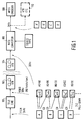
- FIG. 1 illustrates at its left hand side the process of transferring film to videotape.
- a telecine machine 100 is used to scan the frames of a cine film in sequence, to generate video signals which are recorded by a videotape recorder (VTR) 102.
- Video signals conventionally define successive image frames in two interlaced fields, a first field containing the odd numbered lines of the image, and a second field containing the even numbered lines. Due to the different conventions in film and video technologies across the world, the telecine machine functions to adapt the frame rates as follows.
- the original film frames A, B, C, D etc arrive with a 24Hz frequency.
- the resulting video frames, with 60Hz frequency are made up of odd ('O') fields and even ('E') fields in the following 3:2 sequence: AO AE AO BE BO CE CO CE DO DE EO EE EO FE FO GE GO GE HO HE...
- film frame A generates three video fields
- the next film frame B generates two video fields
- C generates three fields
- the pattern repeats every five video frames, ten video fields or four film frames.
- the rate convertor 106 For these purposes it is most desirable for the rate convertor 106 to reconstruct from the recorded video frames a sequence of frames A', B', C' etc which correspond closely to the actual film frames A, B, C.
- Frame BO/CE may contain disturbing motion artifacts, because the odd lines and even lines come from two different film frames. As well as being visually obtrusive, in the MPEG encoder these artifacts 'steal' bandwidth from the true picture information, which is therefore encoded with a lower quality than necessary.
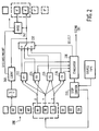
- Figure 2 shows in block schematic form a rate convertor for correctly reconstructing original film frames A', B', C' and so forth from a video sequence. It will be readily apparent to the person skilled in the art how this apparatus can be implemented, whether in hardware, software or in a combination of the two.
- a representative sequence of video fields AO, AE etc. is represented at 200. This sequence arrives continuously from the VTR machine 104. Under the control of a step controller 220, a moving kernel of three fields X, Y, Z is selected for processing.
- X, Y, and Z are the fields BE, BO and CE respectively from the 3:2 pull-down of film sequence A, B, C etc.
- What the apparatus does know is that at least two of the fields X, Y and Z are derived from the same film frame, but there are four possibilities for reconstructing the frame: there may be a frame made from the first two fields X and Y, and/or a frame made from Y and Z. In each of these two cases, the first field may contain the odd lines, or it may contain the even lines.
- the apparatus therefore constructs at 222-228 two pairs of candidate frames, which can be referred to as XY,YX and YZ,ZY.
- Candidate YX thus comprises the first line of field Y, the first line of X, the second line of Y, second line of X and so on.
- These candidate frames are examined by an evaluator 230, which selects a 'best' candidate and controls a selector 232 to cause inclusion of the best candidate frame in the output frame sequence A', B', C' etc.
- evaluator 230 selects a 'best' candidate and controls a selector 232 to cause inclusion of the best candidate frame in the output frame sequence A', B', C' etc.
- candidate YX combines fields BO and BE correctly to generate the desired frame B'.
- the apparatus has no such knowledge, but operates to identify the correct candidate as follows.
- Evaluator 230 takes each line of each candidate frame, and calculates the differences between the pixels of that line and the line below it. These differences are thresholded to discard most of the genuine differences and also random noise. All differences above the threshold are counted up to obtain for each candidate a measure C(XY) etc. of correlation between pixels in adjacent rows over the entire frame. A candidate for which the two fields do not come from the same film frame (such as ZY in the illustrated situation) will tend to have a larger count C(ZY). Also, a candidate where the fields are interlaced incorrectly will have a larger count because the original line 4 is now below line 1, line 6 is now below line 3 and so on. The candidate with the lowest count is then the 'best' of the four candidates.
- the step controller 220 uses knowledge of the video source type (for example '3:2 pull-down from telecine') to implement a 'flywheel' characteristic to arbitrate between these candidates, and also ensures that the kernel follows accurately the 3:2 sequence.
- the flywheel is also important where there is little motion in the picture sequence, so that even the 'wrong' candidates have a very low count of differences. At the same time, the flywheel effect can be overcome automatically when the input sequence includes disruptions of the 3:2 sequence.
- Figure 3 illustrates the operation of the step controller for an input sequence of fields having a 3:2 pattern. Note that the pattern is disrupted in that there should be three fields 'G' between field pairs 'F' and 'H'.
- the step movement of the kernel X-Y-Z is shown below the input sequence, and for each kernel position it is indicated which pair of fields (X and Y or Y and Z) is chosen by the evaluator 230 to form which output field (A', B' etc.). Odd and even fields are not distinguished in Figure 3, for clarity.
- the second pair in the kernel (Y and Z) give the best candidate frame, in other words that the lowest count of pixel differences belongs to candidate YZ or ZY.
- the step size to the next kernel position is made three.
- the first pair is chosen (candidate XY or YX) and the step size is made two.
- the count established for candidates YZ and ZY can be re-used as these candidates are the same as candidates XY and YX after the step. This affords a substantial time saving, particularly in a software embodiment.
- the evaluator favours certain candidates over others to maintain a similar pattern in the step sizes 3-2-3-2-3-2 etc. For example, after finding the 3:2 sequence A-A-A-B-B, the evaluator examines a kernel X-Y-Z in which all three fields come from frame C. Clearly there will be two good candidate frames for C', for example YX and YZ. Because of noise, of course the count of differences might favour candidate XY slightly, but nevertheless a step size of 3 is preferred, and candidate YZ is chosen to continue the 3:2 pattern recently established.
- the condition THIS_STEP equals LAST_STEP identifies cases where simply choosing the candidate frame with the smallest count of differences C(..) would cause a violation of the expected 3:2 sequence. If this condition is met, a further investigation is made to determine whether the pattern should be broken, depending on the magnitude of the difference (
- the threshold value TDIFF is determined adaptively, being set to one fifth of the lower of the two counts SM1 and SM2.
- the threshold is in other words set so that the 'best' candidate will be selected if its count is twenty percent lower than that of the preferred candidate. This is necessary because the counts will vary greatly depending on the scene content.
- a minimum for TDIFF is set at of 150, to avoid spurious results when the scene is almost constant and the counts are all very small.
- the apparatus of Figure 2 therefore includes an up/down counter 240 which compares the number of output frames generated with 5/4 times the number of input video fields received. If a difference accumulates to the extent that the output sequence is a whole frame out of step, the counter generates a discard or insert signal, causing a frame to be discarded from the output sequence, or causing an extra output frame to be inserted, respectively.
- Discarding can be a simple matter (miss out frame B', for example), and similarly inserting a frame can be done simply by repeating one of the output frames (A'-B'-B'-C'-). Note that if a scene cut is known to be present nearby (see below), a frame discarded or inserted immediately before the scene cut will tend to be quite undetectable by the viewer.
- the Figure 2 apparatus includes an averager 242 which can be used to generate a frame in which the pixel values are the average of those in two adjacent frames of the output sequence (A' and B' in the situation illustrated).
- the apparatus will discard two frames and substitute the averaged frame.
- the apparatus will simply add the averaged frame between the two frames.
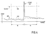
- Figure 4 shows how the evaluator 230 also provides automatic detection of scene cuts (sudden changes in the picture content, not slow 'cross-fades' or 'wipes') in the sequence of output video frames A'-B'-C' etc.
- the MPEG encoder 108 ( Figure 1) can improve data compression and image quality by choosing to encode the frame after a scene cut entirely by 'intra' coding, that is without prediction based on motion estimation with respect to the previous frame.
- Conventional MPEG coders require the engineer controlling the transfer from video to identify visually any scene cuts he/she wants treated in this way. The benefit of automatic detection will be readily apparent when one counts the number of scene cuts included in a typical feature film.
- the vertical axis represents the count of pixel differences for the detected frames, while the field number increases from left to right.
- the detection is based on the principle that two fields derived from film frames either side of a scene cut will normally have very little correlation between their pixel values, so that an extremely high count of pixel differences can be taken as an indication of a scene cut. Even where there is no scene cut, however, the count tends to vary widely in practice, depending on the amount of fast motion in the scene, so that a simple threshold detector will not be a reliable indicator of scene cuts.
- To detect scene cuts evaluator 230 stores the count of differences for the most recent 31 candidate pairs of fields and maintains a running average (line 502 - AVG). The evaluator therefore compares the count for each field pair with a threshold (line 504) which is related to the current average of the counts for the surrounding 31 pairs. It has been found by experiment that a threshold of five times the current average count provides a reliable detection mechanism. Of course other thresholds may be found suitable for different types of video material, and different methods of detection can be envisaged. For a real time encoder, it may be inconvenient to wait for sixteen more field pairs before deciding if the current pair marks a scene cut. In such a case, it may be preferable to determine the threshold only by reference to past field pairs.
- a great quality improvement can be gained by implementing the described techniques, with appropriate regard to the source of the video fields. For example, a different flywheel effect will be necessary for example where simple 2:1 pull-down has been used to transfer film to video at 50 fields/second.
- the preferred step size will be constant at two fields, but this pattern can be violated when the count of differences becomes too large due to editing, field dominance errors and so on.
- the apparatus described is particularly beneficial in that it simplifies the transfer of video recordings for MPEG coding, while also securing high quality for the MPEG coded output.
- the frames being encoded are the original film frames, their self-correlation properties are maximised, allowing the best combination of picture quality and data compression in the MPEG data stream. Apart from the quality of each frame, an overall improvement arises because the encoder doesn't receive more frames than are absolutely necessary to convey the information content.
- the MPEG encoder generally encodes a picture with half as many lines as each of the output frames. It would therefore be possible in principle to encode just one field from each identified frame. It is preferable however to reconstruct the complete frame and then filter to a lower resolution for MPEG encoding. This improves the picture quality, so that the available bandwidth is used to encode real picture information and not aliasing noise. It is found in practice that even a small amount of noise in the images supplied to the MPEG encoder causes a disproportionate loss of quality in the encoded image, because the noise does not have a coherent character and 'steals' from the true picture content a disproportionate amount of bandwidth.
Landscapes
- Engineering & Computer Science (AREA)
- Multimedia (AREA)
- Signal Processing (AREA)
- General Engineering & Computer Science (AREA)
- Compression Or Coding Systems Of Tv Signals (AREA)
- Studio Devices (AREA)
- Television Systems (AREA)
- Details Of Television Scanning (AREA)
Applications Claiming Priority (2)
| Application Number | Priority Date | Filing Date | Title |
|---|---|---|---|
| GB939303369A GB9303369D0 (en) | 1993-02-19 | 1993-02-19 | Identifying film frames in a video sequence |
| GB9303369 | 1993-02-19 |
Publications (3)
| Publication Number | Publication Date |
|---|---|
| EP0612187A2 true EP0612187A2 (fr) | 1994-08-24 |
| EP0612187A3 EP0612187A3 (fr) | 1996-06-05 |
| EP0612187B1 EP0612187B1 (fr) | 1999-12-22 |
Family
ID=10730716
Family Applications (1)
| Application Number | Title | Priority Date | Filing Date |
|---|---|---|---|
| EP94200367A Expired - Lifetime EP0612187B1 (fr) | 1993-02-19 | 1994-02-11 | Identification des trames de film dans une séquence de vidéo |
Country Status (6)
| Country | Link |
|---|---|
| US (1) | US5565998A (fr) |
| EP (1) | EP0612187B1 (fr) |
| JP (1) | JPH06292075A (fr) |
| CN (1) | CN1069480C (fr) |
| DE (1) | DE69422208T2 (fr) |
| GB (1) | GB9303369D0 (fr) |
Cited By (10)
| Publication number | Priority date | Publication date | Assignee | Title |
|---|---|---|---|---|
| EP0673169A3 (fr) * | 1994-03-14 | 1996-07-10 | Thomson Consumer Electronics | Méthode et dispositif pour la détection d'un balayage non-entrelacé et l'élimination de trames. |
| EP0778707A3 (fr) * | 1995-12-06 | 1997-07-16 | Thomson Multimedia Sa | |
| EP0685968A3 (fr) * | 1994-05-31 | 1997-10-01 | Victor Company Of Japan | Dispositif convertisseur de fréquence trame. |
| WO1997039577A1 (fr) * | 1996-04-12 | 1997-10-23 | Snell & Wilcox Limited | Traitement de signaux video avant compression |
| US6064450A (en) * | 1995-12-06 | 2000-05-16 | Thomson Licensing S.A. | Digital video preprocessor horizontal and vertical filters |
| WO2001015170A1 (fr) * | 1999-08-20 | 2001-03-01 | Mti Film, Llc | Marquage de champs video |
| WO2001011866A3 (fr) * | 1999-08-11 | 2002-09-19 | Terran Interactive | Procede et appareil pour realiser un processus de telecine inverse automatise |
| US6538688B1 (en) | 1998-07-02 | 2003-03-25 | Terran Interactive | Method and apparatus for performing an automated inverse telecine process |
| US6842537B2 (en) | 2000-03-31 | 2005-01-11 | Koninklijke Philips Electronics N.V. | Text detection |
| WO2015120443A1 (fr) * | 2014-02-10 | 2015-08-13 | Interdigital Patent Holdings, Inc. | Filtre de télécinéma inverse |
Families Citing this family (43)
| Publication number | Priority date | Publication date | Assignee | Title |
|---|---|---|---|---|
| US6870884B1 (en) * | 1992-01-29 | 2005-03-22 | Mitsubishi Denki Kabushiki Kaisha | High-efficiency encoder and video information recording/reproducing apparatus |
| CA2139420C (fr) | 1992-07-01 | 2000-12-12 | Eric C. Peters | Systeme de montage electronique de pellicules cinematographiques et de bandes video |
| WO1997027704A1 (fr) | 1993-04-21 | 1997-07-31 | Kinya Washino | Systeme de production audio/video multiformat avec conversion de la frequence de trames |
| US6148035A (en) * | 1994-12-29 | 2000-11-14 | Sony Corporation | Processing of redundant fields in a moving picture to achieve synchronized system operation |
| MY113223A (en) * | 1994-12-29 | 2001-12-31 | Sony Corp | Processing of redundant fields in a moving picture to achive synchronized system operation |
| US5757435A (en) * | 1995-12-08 | 1998-05-26 | C-Cube Microsystems, Inc. | MPEG-2 inverse telecine circuit |
| US5798788A (en) * | 1996-02-01 | 1998-08-25 | David Sarnoff Research Center, Inc. | Method and apparatus for evaluating field display functionality of a video decoder |
| US5929902A (en) * | 1996-02-28 | 1999-07-27 | C-Cube Microsystems | Method and apparatus for inverse telecine processing by fitting 3:2 pull-down patterns |
| US5920360A (en) * | 1996-06-07 | 1999-07-06 | Electronic Data Systems Corporation | Method and system for detecting fade transitions in a video signal |
| US5778108A (en) * | 1996-06-07 | 1998-07-07 | Electronic Data Systems Corporation | Method and system for detecting transitional markers such as uniform fields in a video signal |
| US5959697A (en) * | 1996-06-07 | 1999-09-28 | Electronic Data Systems Corporation | Method and system for detecting dissolve transitions in a video signal |
| US6061471A (en) * | 1996-06-07 | 2000-05-09 | Electronic Data Systems Corporation | Method and system for detecting uniform images in video signal |
| US5767923A (en) * | 1996-06-07 | 1998-06-16 | Electronic Data Systems Corporation | Method and system for detecting cuts in a video signal |
| GB9619117D0 (en) * | 1996-09-12 | 1996-10-23 | Pandora Int Ltd | Digital image processing |
| US6108041A (en) * | 1997-10-10 | 2000-08-22 | Faroudja Laboratories, Inc. | High-definition television signal processing for transmitting and receiving a television signal in a manner compatible with the present system |
| US6014182A (en) * | 1997-10-10 | 2000-01-11 | Faroudja Laboratories, Inc. | Film source video detection |
| JP3740813B2 (ja) * | 1997-12-12 | 2006-02-01 | ソニー株式会社 | 画像符号化方法および画像符号化装置 |
| EP0994626A1 (fr) * | 1998-10-12 | 2000-04-19 | STMicroelectronics S.r.l. | Détection de 3:2 pulldown dans une phase d'estimation de mouvement et codeur vidéo optimisé |
| US6870568B1 (en) | 1998-12-02 | 2005-03-22 | Stmicroelectronics Asia Pacific Pte Ltd. | Progressive/interlace and redundant field detection for encoder |
| WO2000051355A1 (fr) | 1999-02-26 | 2000-08-31 | Stmicroelectronics Asia Pacific Pte Ltd | Procede et appareil pour la determination de trames entrelaçees/non entrelaçees, l'identification de champs de repetition et la detection de changements de scenes |
| US6999057B2 (en) * | 2000-02-22 | 2006-02-14 | Kopin Corporation | Timing of fields of video |
| US6897903B1 (en) | 2000-08-31 | 2005-05-24 | Micron Technology, Inc. | Apparatus for detecting mixed interlaced and progressive original sources in a video sequence |
| US7023924B1 (en) | 2000-12-28 | 2006-04-04 | Emc Corporation | Method of pausing an MPEG coded video stream |
| US6937770B1 (en) | 2000-12-28 | 2005-08-30 | Emc Corporation | Adaptive bit rate control for rate reduction of MPEG coded video |
| US20020094026A1 (en) * | 2001-01-12 | 2002-07-18 | Edelson Steven D. | Video super-frame display system |
| US6907081B2 (en) * | 2001-03-30 | 2005-06-14 | Emc Corporation | MPEG encoder control protocol for on-line encoding and MPEG data storage |
| US7174561B2 (en) * | 2001-04-13 | 2007-02-06 | Emc Corporation | MPEG dual-channel decoder data and control protocols for real-time video streaming |
| US6980594B2 (en) | 2001-09-11 | 2005-12-27 | Emc Corporation | Generation of MPEG slow motion playout |
| US6968091B2 (en) * | 2001-09-18 | 2005-11-22 | Emc Corporation | Insertion of noise for reduction in the number of bits for variable-length coding of (run, level) pairs |
| US6959116B2 (en) * | 2001-09-18 | 2005-10-25 | Emc Corporation | Largest magnitude indices selection for (run, level) encoding of a block coded picture |
| US7054367B2 (en) | 2001-12-31 | 2006-05-30 | Emc Corporation | Edge detection based on variable-length codes of block coded video |
| US7664175B1 (en) * | 2004-06-16 | 2010-02-16 | Koplar Interactive Systems International, L.L.C. | Mark-based content modulation and detection |
| US8189877B2 (en) | 2005-10-21 | 2012-05-29 | Carnegie Institution Of Washington | Remote sensing analysis of forest disturbances |
| US20120114167A1 (en) * | 2005-11-07 | 2012-05-10 | Nanyang Technological University | Repeat clip identification in video data |
| TW200806031A (en) * | 2006-07-06 | 2008-01-16 | Realtek Semiconductor Corp | Method and apparatus for entering/leaving film mode when processing video data |
| TWI323610B (en) * | 2006-09-14 | 2010-04-11 | Novatek Microelectronics Corp | Apparatus and method for video de-interlace |
| JP4642734B2 (ja) * | 2006-11-07 | 2011-03-02 | ソニー株式会社 | データ記録装置および方法 |
| US8257217B2 (en) * | 2009-02-03 | 2012-09-04 | Ford Global Technologies, Llc | Infinitely variable transmission with offset output shaft |
| US8260055B2 (en) * | 2009-03-27 | 2012-09-04 | The Nielsen Company (Us), Llc | Methods and apparatus for identifying primary media content in a post-production media content presentation |
| JP4646160B2 (ja) * | 2009-03-30 | 2011-03-09 | ソニー株式会社 | 伝送装置および方法 |
| US8925024B2 (en) | 2009-12-31 | 2014-12-30 | The Nielsen Company (Us), Llc | Methods and apparatus to detect commercial advertisements associated with media presentations |
| JP4983977B2 (ja) * | 2010-11-08 | 2012-07-25 | ソニー株式会社 | データ記録装置および方法、並びに再生装置および方法 |
| US9626567B2 (en) * | 2013-03-13 | 2017-04-18 | Visible Measures Corp. | Automated video campaign building |
Family Cites Families (9)
| Publication number | Priority date | Publication date | Assignee | Title |
|---|---|---|---|---|
| DE3520333A1 (de) * | 1985-06-07 | 1986-12-11 | Robert Bosch Gmbh, 7000 Stuttgart | Verfahren zur bildgenauen uebertragung von filmszenen auf magnetband und schaltungsanordnung hierfuer |
| CA1294033C (fr) * | 1986-12-23 | 1992-01-07 | Wilfred Joseph Giovanella | Methode et systeme de transfert de films sur bande magnetique |
| NL8801347A (nl) * | 1988-05-26 | 1989-12-18 | Philips Nv | Werkwijze en inrichting voor bewegingsdetektie in een geinterlinieerd televisiebeeld verkregen na een filmtelevisie-omzetting. |
| US4998287A (en) * | 1988-10-14 | 1991-03-05 | General Instrument Corporation | Determination of sequential positions of video fields derived from film |
| US4998167A (en) * | 1989-11-14 | 1991-03-05 | Jaqua Douglas A | High resolution translation of images |
| AU8905591A (en) * | 1990-11-16 | 1992-06-11 | Rank Cintel Limited | Video systems |
| EP0514012A3 (en) * | 1991-04-15 | 1993-11-18 | Vistek Electronics | Method and apparatus for the standard conversion of an image signal |
| IL101029A (en) * | 1992-02-20 | 1996-01-19 | Scitex Corp Ltd | Method for identifying elephant type |
| US5365280A (en) * | 1992-06-26 | 1994-11-15 | U.S. Philips Corporation | Method and apparatus for discriminating between movie film and non-movie film and generating a picture signal processing mode control signal |
-
1993
- 1993-02-19 GB GB939303369A patent/GB9303369D0/en active Pending
-
1994
- 1994-02-11 DE DE69422208T patent/DE69422208T2/de not_active Expired - Fee Related
- 1994-02-11 EP EP94200367A patent/EP0612187B1/fr not_active Expired - Lifetime
- 1994-02-16 CN CN94101630A patent/CN1069480C/zh not_active Expired - Fee Related
- 1994-02-17 JP JP6020334A patent/JPH06292075A/ja not_active Ceased
- 1994-02-22 US US08/200,135 patent/US5565998A/en not_active Expired - Lifetime
Cited By (12)
| Publication number | Priority date | Publication date | Assignee | Title |
|---|---|---|---|---|
| EP0673169A3 (fr) * | 1994-03-14 | 1996-07-10 | Thomson Consumer Electronics | Méthode et dispositif pour la détection d'un balayage non-entrelacé et l'élimination de trames. |
| CN1076566C (zh) * | 1994-03-14 | 2001-12-19 | 汤姆森消费电子有限公司 | 非隔行扫描检测和删减场的方法和设备 |
| EP0685968A3 (fr) * | 1994-05-31 | 1997-10-01 | Victor Company Of Japan | Dispositif convertisseur de fréquence trame. |
| EP0778707A3 (fr) * | 1995-12-06 | 1997-07-16 | Thomson Multimedia Sa | |
| US6064450A (en) * | 1995-12-06 | 2000-05-16 | Thomson Licensing S.A. | Digital video preprocessor horizontal and vertical filters |
| WO1997039577A1 (fr) * | 1996-04-12 | 1997-10-23 | Snell & Wilcox Limited | Traitement de signaux video avant compression |
| US6538688B1 (en) | 1998-07-02 | 2003-03-25 | Terran Interactive | Method and apparatus for performing an automated inverse telecine process |
| WO2001011866A3 (fr) * | 1999-08-11 | 2002-09-19 | Terran Interactive | Procede et appareil pour realiser un processus de telecine inverse automatise |
| WO2001015170A1 (fr) * | 1999-08-20 | 2001-03-01 | Mti Film, Llc | Marquage de champs video |
| US6624844B1 (en) | 1999-08-20 | 2003-09-23 | Mti Film Llc | Video field labeling |
| US6842537B2 (en) | 2000-03-31 | 2005-01-11 | Koninklijke Philips Electronics N.V. | Text detection |
| WO2015120443A1 (fr) * | 2014-02-10 | 2015-08-13 | Interdigital Patent Holdings, Inc. | Filtre de télécinéma inverse |
Also Published As
| Publication number | Publication date |
|---|---|
| DE69422208T2 (de) | 2000-07-13 |
| EP0612187B1 (fr) | 1999-12-22 |
| DE69422208D1 (de) | 2000-01-27 |
| CN1069480C (zh) | 2001-08-08 |
| US5565998A (en) | 1996-10-15 |
| CN1095539A (zh) | 1994-11-23 |
| GB9303369D0 (en) | 1993-04-07 |
| EP0612187A3 (fr) | 1996-06-05 |
| JPH06292075A (ja) | 1994-10-18 |
Similar Documents
| Publication | Publication Date | Title |
|---|---|---|
| EP0612187B1 (fr) | Identification des trames de film dans une séquence de vidéo | |
| US6058140A (en) | Method and apparatus for inverse 3:2 pulldown detection using motion estimation information | |
| CN100493186C (zh) | 操纵数据压缩参量的视频内容分析方法和系统 | |
| US6236806B1 (en) | Field detection apparatus and method, image coding apparatus and method, recording medium, recording method and transmission method | |
| US5649047A (en) | Picture reproduction apparatus and picture decoding apparatus | |
| US5174641A (en) | Video encoding method for television applications | |
| US8068175B2 (en) | Method for detecting interlaced material and field order | |
| US6559890B1 (en) | Methods and apparatus for correction of 2-3 field patterns | |
| US6404461B1 (en) | Method for detecting static areas in a sequence of video pictures | |
| JPH11355803A (ja) | 立体映像再生方法 | |
| EP1874055B1 (fr) | Correction pulldown pour l'affichage en balayage progressif d'enregistrements audiovisuels | |
| US5999693A (en) | Flagged video signal processing apparatus and method | |
| EP1163801B1 (fr) | Procede et appareil pour la determination de trames entrelacees/non entrelacees, l'identification de champs de repetition et la detection de changement de scenes | |
| DE60031905T2 (de) | Vorrichtungen zur Übertragung und Empfang von bewegten Bildern sowie Aufzeichnungsmedium für bewegte Bilder | |
| DE69419081T2 (de) | Gerät zur Aufzeichnung von Codes | |
| JP3591712B2 (ja) | 動画送信装置及び動画受信装置 | |
| US8311103B2 (en) | Image recording apparatus for recording image data with display order field | |
| EP0951182A1 (fr) | Méthode pour la détection de zones statiques dans une séquence d'images vidéo | |
| JPH1084545A (ja) | ディジタルビデオ信号の符号化方法及び装置 | |
| JPH10257485A (ja) | 繰り返し画像検出回路及び画像符号化装置 | |
| KR100982509B1 (ko) | 필름 모드 검출방법 및 장치 | |
| WO2000048401A1 (fr) | Appareil et procede de marquage en filigrane de signaux video | |
| KR0162344B1 (ko) | 엠펙-2 시스템의 비트스트림 재생방법 및 장치 | |
| US7095950B2 (en) | Apparatus and method for processing video-ID signal | |
| GB2265782A (en) | Films originating video signal standards conversion |
Legal Events
| Date | Code | Title | Description |
|---|---|---|---|
| PUAI | Public reference made under article 153(3) epc to a published international application that has entered the european phase |
Free format text: ORIGINAL CODE: 0009012 |
|
| AK | Designated contracting states |
Kind code of ref document: A2 Designated state(s): DE FR GB |
|
| PUAL | Search report despatched |
Free format text: ORIGINAL CODE: 0009013 |
|
| AK | Designated contracting states |
Kind code of ref document: A3 Designated state(s): DE FR GB |
|
| 17P | Request for examination filed |
Effective date: 19961205 |
|
| RAP3 | Party data changed (applicant data changed or rights of an application transferred) |
Owner name: KONINKLIJKE PHILIPS ELECTRONICS N.V. Owner name: PHILIPS ELECTRONICS UK LIMITED |
|
| 17Q | First examination report despatched |
Effective date: 19980804 |
|
| GRAG | Despatch of communication of intention to grant |
Free format text: ORIGINAL CODE: EPIDOS AGRA |
|
| GRAG | Despatch of communication of intention to grant |
Free format text: ORIGINAL CODE: EPIDOS AGRA |
|
| GRAH | Despatch of communication of intention to grant a patent |
Free format text: ORIGINAL CODE: EPIDOS IGRA |
|
| GRAH | Despatch of communication of intention to grant a patent |
Free format text: ORIGINAL CODE: EPIDOS IGRA |
|
| GRAA | (expected) grant |
Free format text: ORIGINAL CODE: 0009210 |
|
| AK | Designated contracting states |
Kind code of ref document: B1 Designated state(s): DE FR GB |
|
| REF | Corresponds to: |
Ref document number: 69422208 Country of ref document: DE Date of ref document: 20000127 |
|
| ET | Fr: translation filed | ||
| PLBE | No opposition filed within time limit |
Free format text: ORIGINAL CODE: 0009261 |
|
| STAA | Information on the status of an ep patent application or granted ep patent |
Free format text: STATUS: NO OPPOSITION FILED WITHIN TIME LIMIT |
|
| 26N | No opposition filed | ||
| REG | Reference to a national code |
Ref country code: GB Ref legal event code: IF02 |
|
| PGFP | Annual fee paid to national office [announced via postgrant information from national office to epo] |
Ref country code: FR Payment date: 20040226 Year of fee payment: 11 |
|
| PGFP | Annual fee paid to national office [announced via postgrant information from national office to epo] |
Ref country code: GB Payment date: 20040227 Year of fee payment: 11 |
|
| PGFP | Annual fee paid to national office [announced via postgrant information from national office to epo] |
Ref country code: DE Payment date: 20040415 Year of fee payment: 11 |
|
| PG25 | Lapsed in a contracting state [announced via postgrant information from national office to epo] |
Ref country code: GB Free format text: LAPSE BECAUSE OF NON-PAYMENT OF DUE FEES Effective date: 20050211 |
|
| PG25 | Lapsed in a contracting state [announced via postgrant information from national office to epo] |
Ref country code: DE Free format text: LAPSE BECAUSE OF NON-PAYMENT OF DUE FEES Effective date: 20050901 |
|
| GBPC | Gb: european patent ceased through non-payment of renewal fee |
Effective date: 20050211 |
|
| PG25 | Lapsed in a contracting state [announced via postgrant information from national office to epo] |
Ref country code: FR Free format text: LAPSE BECAUSE OF NON-PAYMENT OF DUE FEES Effective date: 20051031 |
|
| REG | Reference to a national code |
Ref country code: FR Ref legal event code: ST Effective date: 20051031 |