EP0612573A2 - Valve pour désaérer des moules de coulée sous pression - Google Patents
Valve pour désaérer des moules de coulée sous pression Download PDFInfo
- Publication number
- EP0612573A2 EP0612573A2 EP94810013A EP94810013A EP0612573A2 EP 0612573 A2 EP0612573 A2 EP 0612573A2 EP 94810013 A EP94810013 A EP 94810013A EP 94810013 A EP94810013 A EP 94810013A EP 0612573 A2 EP0612573 A2 EP 0612573A2
- Authority
- EP
- European Patent Office
- Prior art keywords
- valve
- piston
- working
- vent
- valve device
- Prior art date
- Legal status (The legal status is an assumption and is not a legal conclusion. Google has not performed a legal analysis and makes no representation as to the accuracy of the status listed.)
- Granted
Links
Images


Classifications
-
- B—PERFORMING OPERATIONS; TRANSPORTING
- B29—WORKING OF PLASTICS; WORKING OF SUBSTANCES IN A PLASTIC STATE IN GENERAL
- B29C—SHAPING OR JOINING OF PLASTICS; SHAPING OF MATERIAL IN A PLASTIC STATE, NOT OTHERWISE PROVIDED FOR; AFTER-TREATMENT OF THE SHAPED PRODUCTS, e.g. REPAIRING
- B29C33/00—Moulds or cores; Details thereof or accessories therefor
- B29C33/10—Moulds or cores; Details thereof or accessories therefor with incorporated venting means
-
- A—HUMAN NECESSITIES
- A41—WEARING APPAREL
- A41C—CORSETS; BRASSIERES
- A41C3/00—Brassieres
- A41C3/12—Component parts
- A41C3/122—Stay means
- A41C3/124—Stay means with an articulated or bridge construction
-
- B—PERFORMING OPERATIONS; TRANSPORTING
- B22—CASTING; POWDER METALLURGY
- B22D—CASTING OF METALS; CASTING OF OTHER SUBSTANCES BY THE SAME PROCESSES OR DEVICES
- B22D17/00—Pressure die casting or injection die casting, i.e. casting in which the metal is forced into a mould under high pressure
- B22D17/14—Machines with evacuated die cavity
- B22D17/145—Venting means therefor
Definitions
- the invention relates to a valve device for venting die casting molds, with a vent channel, a vent valve arranged in the vent channel and an actuating device for closing the vent valve, the actuating device having a force transducer which can be acted upon by casting material penetrating from the mold cavity into the vent channel and with the movable one Closing part of the vent valve is in a mechanical operative connection.
- Valve devices of this type are normally mounted on one of two abutting molded parts of the die, on the outer edge of the abutting surface in question, and have a front surface aligned with the abutting surface, which, when the mold is closed, lies tightly against the abutting surface of the other molded part.
- the venting channel of the valve device is open towards its front surface and forms the continuation of the venting channel of the die casting mold provided on the relevant molded part, leading out of the mold cavity and also open towards the butting surface.
- the outwardly leading end of the ventilation channel of the valve device can either remain open or be connected to a vacuum pump which sucks off the air contained in the mold cavity and displaced by the casting material flowing into the die.
- a vent valve which is closed after the venting process, is intended to prevent liquid casting material from getting outside or into the vacuum pump.
- the closing process of the ventilation valve is triggered by the casting material penetrating into the ventilation channel of the valve device.
- a dynamic pressure of the advancing casting material built up in the valve device is mechanically converted into a force which causes the ventilation valve to close.
- this force conversion should take place with a minimal time delay in order to ensure that the closing process ends is before the casting material has reached the vent valve. Above all, it must be avoided that casting material can penetrate into the passage area of the vent valve, because otherwise it will lose its functionality.
- valve device of the type described at the outset is known, which is used in the aforementioned manner and meets the stated requirements.
- This valve device contains a piston valve, the longitudinal axis of which runs perpendicular to the front of the valve device and which has a valve cylinder connected to the venting channel and a valve piston movable therein.
- the valve piston is provided with a piston head which, when the ventilation valve is open, projects into the ventilation channel on the front of the valve device and dips into the valve cylinder to close the ventilation valve.
- the actuating device has a cylinder arrangement with a working cylinder, which is connected to a section of the ventilation duct located in the flow direction upstream of the piston valve, and with a working piston which can be acted upon by the inflowing casting material.
- the working cylinder of the actuating device and the valve cylinder of the piston valve are arranged axially parallel to one another, and the working piston is connected to the valve piston in such a way that the working piston acted upon by the casting material and set in motion causes the valve piston to move in the closing direction.
- the working piston of the actuating device with the valve piston of the venting valve is either direct or by means of a driver positively connected, this driver moves on an axially parallel path with these pistons.
- the working piston only acts non-positively on the driver.
- the path that the working piston covers when it is actuated is the same as the closing path of the valve piston, which can be, for example, 5 to 10 mm. This has proven to be disadvantageous for various reasons.
- the mass set in motion (working piston, driver, valve piston) reaches a relatively high kinetic energy at the end of the distance traveled, which must be reduced again by braking the moving mass.
- a hard end stop of the moving mass could possibly destroy the valve device.
- Suitable means for shock absorption are therefore required, which are, however, quite complex, especially when only a short braking distance or a short braking time is available.
- the plunger of the vent valve has a defined immersion depth. If this immersion depth is extended, even if only temporarily, by the braking process, casting material penetrating into the cylinder space can endanger the functional reliability of the vent valve.
- the invention is therefore based on the object of improving the valve device of the type mentioned at the outset by measures which, while avoiding the disadvantages mentioned, reduce the kinetic energy to be absorbed by the force transducer to a level which is sufficient for closing the venting valve, in order thereby to operate the valve more favorably Allow actuator.
- the kinetic energy of the force transducer can be kept within acceptable limits due to the shortened working stroke of the force transducer and without special shock absorption measures can be safely caught at a fixed stop.
- the closure part of the vent valve which is set in motion by the force pulse, continues to move freely in the closing direction. Through this freewheeling, ie through the release of the force connection between the short-stroke thrust member and the mass set in motion after the force impulse, it is also achieved that most of the working distance of this remaining mass is available as a braking distance for the conversion of the kinetic energy of the same .
- the braking means required for this purpose can accordingly be simpler and less expensive than a shock absorber for the entire mass to be braked only at the end of the working path determined by the closing path of the vent valve.
- the closing time of the vent valve is not extended by the free running of the closure part and is in the order of 1 msec.
- the pushing element acted upon by the casting material is designed as a free piston which can be moved in a working cylinder opening into the venting channel, the part of the cylinder surface accessible to the advancing casting material can also be moved because of the short working stroke of the free piston of the working cylinder so short that a cone formation on the solidifying casting material and thus the resulting disadvantages are largely avoided.
- the force transducer is also the possibility of designing the force transducer as a membrane, which closes an opening of the ventilation channel.
- the working stroke of the membrane corresponds to the working path of the organ influenced by the membrane. In any case, there is no question of a free running of the movable closure part of the ventilation valve.
- the force transducer of the actuating device and the vent valve are arranged at spatially separate locations on the vent channel of the valve device. For this reason, a direct mechanical action of the force transducer on the movable closure part of the vent valve is generally not possible. Rather, it is generally expedient to equip the actuating device with a force transmission element for the transmission of the shock pulse from the force transducer to the movable closure part of the ventilation valve, which bridges the mutual spacing of these parts which is present for design reasons.
- the force transmission element could e.g. consist of a shoulder with radial expansion provided on the free piston, which works together with the movable closure part of the vent valve.
- the axially guided free piston is loaded on one side during the power transmission by the mass of the closure part to be moved.
- the transverse forces that occur on the free piston can result in excessively high friction losses, which result in increased wear of the piston guide and, under certain circumstances, can result in premature failure of the actuating device.
- a solution has proven to be more advantageous in which the force transmission element is non-positively connected to the force transducer and positively connected to the movable closure part of the vent valve.
- the vent valve is preferably designed as a piston valve with plunger and the pushing element, like known force transducers, is arranged axially parallel to the piston valve.
- the force transmission member can have an axially movable and coaxially arranged to the thrust member driving plate, which is positively connected at its periphery with the plunger of the vent valve is and in the rest position of the actuating device rests under spring force against an abutment surface of the abutment member.
- the actuating device has a closing element which is in operative connection with the movable closure part of the vent valve and holds it in the closed position reached by the force impulse of the pushing element.
- the closing element is, for example, a working cylinder with a pneumatically or hydraulically actuated working piston, the working piston being positively connected to the movable closure part, that is to say, for example, to the plunger of the vent valve by a rigid connecting member.
- the working cylinder of the closing element is preferably arranged axially parallel to the pushing element of the actuating device.
- the drive plate can form the rigid connecting member and can be positively connected both to the movable closure part of the ventilation valve and to the working piston of the closing element.
- valve device has been found to be particularly advantageous, which is characterized in that the movable closure part of the vent valve and the working piston of the closing member are connected to the driving disk at diametrical locations on the latter.
- a certain mass balance can be achieved by the symmetrical arrangement of the masses connected to the driving plate and to be moved thereby, whereby lateral forces in the longitudinal guides of the moving parts are largely avoided. No transverse forces come into effect on the impact element, since it is connected to the force transmission element only by a force fit, that is to say not in a form-fitting manner.
- a preferred embodiment consists in that the pneumatic or hydraulic action on the working piston of the closing element takes place via a control valve actuated by the movable closure part of the vent valve.
- the working piston of the closing element generates a force already during the closing movement of the closing part of the venting valve, which supports the closing force and is independent of the respective pushing force of the pushing element.
- the closure part moving in free running also comes into its closed position when the force impulse imparted to the closure part by the pushing element is insufficient under certain circumstances. This is the valve device is less dependent on the pressure conditions in the die.
- the impact stroke of the force transducer is preferably less than 1 mm. Under certain circumstances, an impact stroke of the order of magnitude of 0.1 mm can be selected, provided the kinetic energy of the casting material penetrating into the valve device is sufficiently high. This can be the case with large die casting molds and high casting pressure.
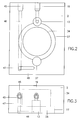
- the valve device 1 according to FIGS. 1 to 6 is accommodated in a cuboid, two-part housing block 2, 3, which is divided along the parting plane 4 into a rear housing block part 2 and into a front housing block part 3 forming a flat front surface 5.
- the housing block 2, 3 is mounted in a known manner on a molded part 6 of two colliding molded parts 6, 7 of the die-casting mold, which are only partially shown in the drawing, on the outer edge of the abutting surface 8 in question.
- the front surface 5 of the housing block 2, 3 lies with the butt surface 8 of the molded part 6 in alignment, so that when the mold is closed, the front surface 5, like the butt surface 8, lies tightly against the abutting surface 9 of the other molded part 7.
- the housing block 2, 3 is fastened to the molded part 6 and the housing block parts 2 and 3 are mutually fastened by means of screws, which are not shown in the drawing.
- a ventilation duct is provided in a known manner and is open to the front surface 5.
- This ventilation duct 10 of the valve device 1 which is described in more detail in connection with FIG. 4, forms the continuation of the ventilation duct 11 of the die casting mold provided on the relevant molded part 6, which leads out of the mold cavity and is also open towards the butt surface 8.
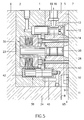
- the vent valve 12 of the valve device 1 is a plunger valve of the type known, for example, from CH-PS 633 208, the longitudinal axis of which extends perpendicularly to the front surface 5 of the housing block 2, 3 and the one valve cylinder 13 connected to the vent channel 10 and a valve piston movable therein 14 has.
- the valve piston 14 is provided with a piston head 15 which, when the ventilation valve 12 (FIGS. 1, 5) is open, projects into the ventilation channel 10 on the front side of the valve device 1 and dips into the valve cylinder 13 to close the ventilation valve 12 (FIG. 6).
- At the top of the housing block part 3 are the outlet channel 16 of the vent valve 12 to which the suction line of a vacuum pump (not shown) can be connected.
- the space 18 of the valve cylinder 13 located behind a rear cylindrical extension 17 of the valve piston 14 is connected within the housing block part 2 to a channel 19 leading to the outside, to which, for example, a sensor for monitoring the valve function can be connected.
- a multi-part actuating device is provided to close the vent valve 12.
- the main part of this actuating device is a force transducer which can be acted upon by casting material penetrating from the mold cavity into the ventilation channel 10 and which is in mechanical operative connection with the valve piston 14 of the ventilation valve 12.
- the force transducer is a short-stroke thrust member, which in the present example is designed as a free piston 20, which can be moved in a working cylinder 21 opening into the ventilation duct 10.
- the longitudinal axis of the working cylinder 21 runs parallel to that of the vent valve 12.
- a rear cylindrical extension 22 of the free piston 20 extends into the vicinity of a rear wall 23 of the housing block part 2.
- a force transmission element in the form of a drive plate 24 is provided, which is arranged axially parallel to the free piston 20 and is axially displaceably mounted with a hub 25 on its extension 22.
- the axial movement of the drive plate 24 is limited on the one hand by the housing block part 3 at the parting plane 4 and on the other hand by the shoulder 26 of a cylindrical recess 27 (FIG. 2) in the housing block part 2.
- the free piston 20 is provided with a collar 28 which is in the center of the drive plate 24 non-positively engages 20 during the working stroke of the free piston.
- the drive plate 24 engages in a groove in the extension 17 of the valve piston 14 at the point 29 of its peripheral edge and is thus positively connected to the valve piston 14.
- a spring arrangement 30 is used with a spring assembly 31 formed from disc springs, which is arranged between a stationary pressure plate 32 and an axially movable pressure plate 33 within a bore 34 of the housing block part 2 is.
- a sleeve extension 35 which loosely surrounds the hub 25 of the drive plate 24 and closes the spring assembly 31 on the inside.
- two plungers 36 and 37 are present, which pass through the housing block part 3 and the drive plate 24 in an axially freely movable manner and on of the movable pressure plate 33 of the spring assembly 30.
- the plungers 36, 37 protrude from the housing block part 3 via the front surface 5 and are pushed back by the joint surface 9 of the molded part 7 when the two molded parts 6 and 7 of the die casting mold are brought together, which leads to tensioning of the spring arrangement 30 (FIG. 5).
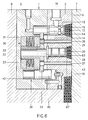
- the plungers 36, 37 mentioned are shown as lying in a common vertical plane for a better understanding of the functioning of the valve device 1. In fact, however, with regard to the shape of the ventilation duct 10, they are arranged lying in a common horizontal plane (FIG. 4).
- the actuating device further comprises a closing member 38 which is in operative connection with the valve piston 14 of the vent valve 12 and holds it in the closed position reached by the force pulse of the free piston 20.
- the closing element 38 is not necessary in every application; however, the presence of the same is useful for a wider range of valve device applications.
- the closing member 38 is a working cylinder 39 with a pneumatically or hydraulically actuated working piston 40, which is arranged axially parallel to the ventilation valve 12.
- the working piston 40 is positively connected to the driving plate 24 in the same way as the valve piston 14, to be precise on one the point 29 opposite the point 41 of the disk edge. In this way, the working piston 40 of the closing member 38 and the valve piston 14 of the vent valve 12 are positively connected to one another by the drive plate 24 forming a rigid connecting member.
- the working piston 40 of the closing element 38 is under the action of a return spring 42 which, when the spring arrangement 30 is tensioned, presses the drive plate 24 against the collar 28 of the free piston 20 and at the same time holds the valve piston 14 of the vent valve 12 in the open position.
- the pneumatic or hydraulic actuation of the working piston 40 is basically carried out via a control valve actuated by the valve piston 14 of the vent valve 12. Due to the rigid connection between the valve piston 14 of the vent valve 12 and the working piston 40 of the closing element 38, it has proven to be expedient to provide a poppet valve as the control valve, the working piston 40 of the closing element 38 forming the valve disk.
- the working cylinder 39 of the closing element 38 has an inlet nozzle 43 projecting into the end of the cylinder space, the working piston 40 closing the nozzle opening 44 under the action of the return spring 42 with its end face facing the nozzle opening 44.
- the pneumatic or hydraulic pressure medium is supplied via an inlet opening 45 (FIGS. 2, 3) and the channels 46, 47 and 48 running within the housing block part 2 and the channels 49 running inside the housing block part 3 , 50 and 51 to the inlet nozzle 43.
- the pressure of the pressure medium for operating the closing element 38, the ratio of the passage cross section of the inlet nozzle 43 to the cross section of the working piston 40 and the properties of the return spring 42 acting on the working piston 40 are selected such that when the control valve 40, 43 is closed, the one prevailing in the inlet nozzle 43 , pressure of the pressure medium acting on part of the piston cross section is not sufficient to open the control valve 40, 43, but that after the mechanical opening of the control valve of the working piston 40 by the pressure exerted on its entire end face, the vent valve 12 is closed and closed in its closed position can hold.
- the venting duct 10 of the valve device 1 consists of numerous branch ducts 52 to 59 and chambers 60 to 62, which, as is known, in their overall arrangement serve to collect splashes which lead the compact flow of casting material, to increase the dynamic pressure at the free piston 20 and the flow of the liquid casting material to delay the vent valve 12.
- a collecting chamber 60 arranged at the entrance of the ventilation duct 10 the two branch ducts 52 and 53 lead to an extension 63 upstream of the working cylinder 21 of the pushing element.
- the two following branch ducts 54 and 55 each lead to a delay chamber 61 and 62, respectively which the further branch channels 56, 58 and 57, 59 lead to an extension 64 upstream of the valve cylinder 13 of the vent valve 12.
- valve device 1 in the ready state.
- the die is closed, i.e. the molded part 7 lies with its abutting surface 9 close to the abutting surface 8 of the molded part 6 or on the front surface 5 of the valve device 1.
- the spring assembly 30 was tensioned using the plungers 36, 37.
- the vent valve 12 is still in the open position under the action of the return spring 42 of the closing element 38, so that the air displaced from the mold cavity in the flow direction indicated by the arrows 65, 66 via the vent channel 11 of the die casting mold, the vent channel 10 of the valve device 1, the opened vent valve 12 and the outlet channel 16 escape.
- the control valve 40, 43 of the closing member 38 is still closed.
- the liquid casting material flowing out of the mold cavity of the die casting mold via its ventilation channel 11 penetrates into the ventilation channel 10 of the valve device 1 and reaches the free piston 20 of the actuating device via the branch channels 52, 53 (FIG. 4).
- the short-stroke free piston 20 is suddenly moved against the end stop of its extension 22 on the rear wall 23 of the housing block part 2.
- the collar 28 on the free piston 20 transmits this force impulse to the drive plate 24, which, under the effect of the kinetic energy imparted to it by the free piston 20, stands out from the collar 28 of the free piston 20 after it has reached its end position, and together with the valve piston 14 of the vent valve 12 and the working piston 40 of the closing element 38 is thrown against the force of the return spring 42 of the closing element 38.
- the vent valve 12 is closed by the valve piston 14 being immersed in the valve cylinder 13.
- vent valve 12 The closing movement of the vent valve 12 is supported by the working piston 40 of the closing member 38, which is now under the full effect of the pressure medium after the opening of the control valve 40, 43 by the impact of the free piston 20 and its force acting in the closing direction from the drive plate 24 to the Valve piston 14 of the vent valve 12 is transmitted.
- FIG. 6 shows the state of the valve device 1, as casting material 67 penetrating from the mold cavity into the ventilation channel 10 has reached the extension 63 in front of the free piston 20 and shortly thereafter (for example after less than 1 msec) also up to the extension 64 in front of the Valve piston 14 of the vent valve 12 has reached.
- the vent valve 12 has already been closed, the valve piston 14 having reached the end of its closing path in the manner described above. This ensures that the casting material flowing on via the branch channels 56 to 59 to the extension 64 cannot get into the vent valve 12 and the outlet channel 16.
- the spring arrangement 30 can relax, since the plungers 36, 37 are released from the abutment surface 9 by the removal of the mold part 7.
- the spring arrangement 30 now, under the action of the tensioned spring assembly 31, presses the drive plate 24 and thus the valve piston 14 of the vent valve 12 and the working piston 40 of the closing element 38 and finally the free piston 20 back into the starting position according to FIG. 1.
- the head 15 of the valve piston 14 and the end face of the free piston 20 press the pins of the solidified casting material formed in the extensions 63, 64 away, so that the entire riser is released from its anchoring in the ventilation duct 10.
- the control valve 40, 43 is closed again for the actuation of the closing member 38.
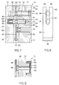
- valve device 71 shows the basic structure of another embodiment of the valve device according to the invention in a smaller scale Scale.
- This valve device 71 is also accommodated in a cuboid housing block 72, 73 which is divided along the parting plane 74 into a rear housing block part 72 and a front housing block part 73 forming a flat front surface 75.
- the valve device 71 can be mounted on a molded part, not shown here, of a multi-part die casting mold.
- a piston valve is also provided as the ventilation valve 76, which has a valve cylinder 78 with outlet channel 79 connected to the ventilation channel 77 and an axially movable plunger 80 with piston head 81.
- a free piston 82 which can be acted upon by the casting material, which in turn is axially movable in a working cylinder 83 and whose working stroke is limited by a shoulder 84 in the working cylinder 83, serves as the thrust member.
- the free piston 82 has a plunger 85 with a plunger head 86, the latter protruding into a cutout 87 in the rear housing block part 72 and resting on the parting plane 74 of the front housing block part 73 in the idle state.
- the closing element 88 is constructed in a similar manner to the closing element 38 according to FIG. 1 and has a working cylinder 89 with a working piston 91 which is under the action of a return spring 90.
- the working piston 91 can be acted upon pneumatically or hydraulically by a pressure medium which is fed via a line 92 to a nozzle 93 opening into the working cylinder 89.
- An end face 94 on the working piston 91 closes the opening of the nozzle 93 in the idle state thereof and forms with it the control valve for the pneumatic or hydraulic actuation of the working piston 91.
- the transmission of the force pulse from the free piston 82 to the valve piston 80 of the vent valve 76 and the working piston 82 of the closing element 88 does not take place via a linearly moving force transmission element (drive plate 24), but via one Swivel lever 95, which is arranged in the cutout 87 of the housing block part 72 and is mounted with a joint head 96 on a swivel axis 97.
- the swivel lever 95 is positively connected to a rearward extension 98 of the valve piston 80 of the vent valve 76 and to the working piston 91 of the closing element 88 by two arms 99 of the swivel lever 95, which is fork-shaped at its free end according to FIG. 8, laterally in a circumferential groove 100 or 101 engage the extension 98 and the piston 91.
- this intervention involves the necessary play.
- valve device according to FIGS. 7 and 8 functions in the same way as that according to FIGS. 1 to 6.
- the short-stroke free piston 82 throws the pivot lever 95 away so that Vent valve 76 is closed and is held in its closed position by the closing member 88.
- a diaphragm 102 is provided as a thrust member, which closes an opening 103 of the ventilation duct on the front side 75 of the valve device 71 and is fastened to the housing block part 73 with a ring nut 104.
- the plunger 85 which also has a plunger head 86 which interacts with the pivoting lever 95, is here extended to the diaphragm 102.
- a slightly conical stop surface 105 is formed behind the membrane 102, which limits the stroke of the membrane 102 to a dimension which is only a fraction of the closing distance to be covered by the valve piston 80 (FIG. 7).
- a membrane arrangement of this type can of course also be provided in the embodiment according to FIGS. 1 to 6 instead of the free piston 20.
Landscapes
- Engineering & Computer Science (AREA)
- Mechanical Engineering (AREA)
- Textile Engineering (AREA)
- Moulds For Moulding Plastics Or The Like (AREA)
- Molds, Cores, And Manufacturing Methods Thereof (AREA)
- Self-Closing Valves And Venting Or Aerating Valves (AREA)
- Forging (AREA)
- Separation By Low-Temperature Treatments (AREA)
- Medicines Containing Material From Animals Or Micro-Organisms (AREA)
- Control Of Fluid Pressure (AREA)
- Catching Or Destruction (AREA)
- Fodder In General (AREA)
- Heating, Cooling, Or Curing Plastics Or The Like In General (AREA)
- Corsets Or Brassieres (AREA)
- Valve Housings (AREA)
- Lift Valve (AREA)
- Body Structure For Vehicles (AREA)
Applications Claiming Priority (2)
| Application Number | Priority Date | Filing Date | Title |
|---|---|---|---|
| DE4302798A DE4302798C1 (de) | 1993-02-02 | 1993-02-02 | Ventileinrichtung zum Entlüften von Druckgiessformen |
| DE4302798 | 1993-02-02 |
Publications (3)
| Publication Number | Publication Date |
|---|---|
| EP0612573A2 true EP0612573A2 (fr) | 1994-08-31 |
| EP0612573A3 EP0612573A3 (fr) | 1995-02-22 |
| EP0612573B1 EP0612573B1 (fr) | 1998-03-04 |
Family
ID=6479385
Family Applications (1)
| Application Number | Title | Priority Date | Filing Date |
|---|---|---|---|
| EP94810013A Expired - Lifetime EP0612573B1 (fr) | 1993-02-02 | 1994-01-11 | Valve pour désaérer des moules de coulée sous pression |
Country Status (20)
| Country | Link |
|---|---|
| US (1) | US5488985A (fr) |
| EP (1) | EP0612573B1 (fr) |
| JP (1) | JP3284727B2 (fr) |
| KR (1) | KR100306452B1 (fr) |
| CN (1) | CN1054792C (fr) |
| AT (1) | ATE163584T1 (fr) |
| AU (1) | AU674903B2 (fr) |
| CA (1) | CA2114581C (fr) |
| CZ (1) | CZ284138B6 (fr) |
| DE (2) | DE4302798C1 (fr) |
| DK (1) | DK0612573T3 (fr) |
| ES (1) | ES2114671T3 (fr) |
| FI (1) | FI100951B (fr) |
| HK (1) | HK1003593A1 (fr) |
| HU (1) | HU216702B (fr) |
| IL (1) | IL108454A (fr) |
| LV (1) | LV12087B (fr) |
| PL (1) | PL178221B1 (fr) |
| RU (1) | RU2082546C1 (fr) |
| TW (1) | TW235256B (fr) |
Cited By (6)
| Publication number | Priority date | Publication date | Assignee | Title |
|---|---|---|---|---|
| EP0937524A1 (fr) * | 1998-02-19 | 1999-08-25 | Fondarex S.A. | Procédé pour désaérer des moules à couler sous pression et dispositif à valve pour la mise en oeuvre de ce procédé |
| EP1018384A1 (fr) * | 1999-01-06 | 2000-07-12 | Fondarex S.A. | Dispositif de soupape |
| EP1295655A1 (fr) * | 2001-09-21 | 2003-03-26 | Fondarex S.A. | Dispositif de soupape pour l'évacuation des moules de fonderrie |
| EP2239070A1 (fr) | 2009-04-06 | 2010-10-13 | Fondarex S.A. | Dispositif de coulée |
| DE102015004024A1 (de) | 2014-11-07 | 2016-05-12 | Fondarex S.A. | Ventileinrichtung zum Entlüften von Druckgießformen |
| EP3375547A1 (fr) * | 2017-03-16 | 2018-09-19 | Fondarex S.A. | Système de ventillation pour machine de coulée sous pression |
Families Citing this family (32)
| Publication number | Priority date | Publication date | Assignee | Title |
|---|---|---|---|---|
| CA2430276C (fr) * | 1991-06-27 | 2007-03-20 | Unicast Technologies Inc. | Matrice utilise dans une machine a couler sous pression |
| ATE240808T1 (de) * | 1998-02-11 | 2003-06-15 | V D S Vacuum Diecasting Servic | Ventilvorrichtung, insbesondere entlüftungsventil-vorrichtung für den druckguss |
| IT1309221B1 (it) * | 1999-07-02 | 2002-01-16 | Edoardo Bresciani | Valvola di aspirazione per scaricare aria e gas dagli stampi per lapressofusione |
| IT250560Y1 (it) * | 2000-08-24 | 2003-09-24 | Bresciani Edoardo | Compensatore per la chiusura forzata di valvole di aspirazione instampi per la pressofusione |
| TW579311B (en) * | 2000-09-22 | 2004-03-11 | V D S Vacuum Diecasting Servic | Diecasting valve |
| EP1266707A1 (fr) * | 2001-06-13 | 2002-12-18 | Alcan Technology & Management AG | Clapet à vide pour machine de coulée sous pression |
| DE10327108B4 (de) * | 2003-06-13 | 2007-10-18 | Bernd Radke | Ventil mit Tellerfeder |
| BRPI0406493A (pt) * | 2004-12-30 | 2006-09-05 | Unilever Nv | dispositivo, equipamento e processo de fabricação de artigo de limpeza com uma massa fluìda e possuindo formas complexas e uso do artigo de limpeza |
| TWI296564B (en) * | 2005-07-29 | 2008-05-11 | Delta Electronics Inc | Gas exhausting and entering structure |
| DE102005039431B3 (de) * | 2005-08-18 | 2007-01-25 | InterGuss Gießereiprodukte GmbH | Vorrichtung zur Verringerung der Strömungsgeschwindigkeit im Bereich eines Entlüftungskanals einer Gussform |
| KR100782756B1 (ko) * | 2006-12-21 | 2007-12-05 | 주식회사 포스코 | 유량 조절기가 설치된 냉간압연용 형상제어장치 |
| JP2012152779A (ja) * | 2011-01-25 | 2012-08-16 | Ryobi Ltd | ダイカスト用金型及びダイカスト法 |
| EP2388088A1 (fr) * | 2010-05-18 | 2011-11-23 | Georg Fischer Verwaltungs-GmbH | Pièce d'un moule de coulée sous pression et dispositif de coulée sous pression correspondant |
| CH705077B1 (fr) * | 2011-06-09 | 2016-01-29 | V D S Vacuum Diecasting Service S A | Dispositif de vanne pour l'évacuation d'air d'un moule. |
| TWI473678B (zh) * | 2012-03-07 | 2015-02-21 | Univ Nat Taiwan Ocean | 閥門結構 |
| KR101551967B1 (ko) | 2013-12-26 | 2015-09-09 | 현대자동차주식회사 | 고효율 고진공 다이캐스팅 장치 |
| KR101527788B1 (ko) * | 2015-04-08 | 2015-06-12 | 캐스트테크(주) | 다이캐스팅 금형 통기를 위한 일원화된 구조의 밸브 조립체 |
| CN107321956B (zh) * | 2016-04-29 | 2019-06-11 | 长城汽车股份有限公司 | 压铸模具真空阀 |
| CN106704619A (zh) * | 2017-02-23 | 2017-05-24 | 广州市型腔模具制造有限公司 | 气动真空阀 |
| CN107345574B (zh) * | 2017-07-31 | 2023-07-25 | 上海皮尔博格有色零部件有限公司 | 一种压铸模具的型腔排气系统 |
| CN108253181A (zh) * | 2018-01-12 | 2018-07-06 | 江苏远洋阀门智控股份有限公司 | 一种真空截止阀 |
| CN108311658A (zh) * | 2018-02-08 | 2018-07-24 | 山东弗泽瑞金属科技有限公司 | 真空低速压铸方法 |
| JP7068880B2 (ja) * | 2018-03-26 | 2022-05-17 | 本田技研工業株式会社 | 減圧遮断弁装置及びその制御方法 |
| CN108480596B (zh) * | 2018-05-22 | 2020-03-31 | 宁波北仑益鸣企业管理服务有限公司 | 一种用于压铸模具的真空阀抽气装置 |
| KR102124618B1 (ko) | 2018-09-14 | 2020-06-18 | 주식회사 상익기공 | 다이캐스팅금형의 가스배출장치용 벤트밸브 |
| KR102453483B1 (ko) * | 2021-01-14 | 2022-10-12 | (주)세아메카닉스 | 다이캐스팅 주조기용 진공블럭 검사장치 |
| CN112959622B (zh) * | 2021-02-07 | 2022-11-18 | 杭州乐创塑业有限公司 | 一种塑料用品注塑模具 |
| CN113103516B (zh) * | 2021-04-13 | 2022-06-28 | 台州市黄岩云天模塑有限公司 | 一种便于排气的注塑模具 |
| KR102666180B1 (ko) | 2022-04-28 | 2024-05-16 | 캐스트테크 주식회사 | 다이캐스팅용 진공밸브블록 |
| DE102022114043A1 (de) | 2022-06-02 | 2023-12-07 | Fondarex Sa | Verfahren zur Steuerung und/oder Regelung eines Vakuumventils an einer Kavität eines Gießwerkzeugs |
| CN118669572B (zh) * | 2024-07-08 | 2024-12-20 | 重庆理工大学 | 一种铸造用的真空排气阀 |
| CN120133495B (zh) * | 2025-03-20 | 2026-03-03 | 临海市兴业精密铸造有限公司 | 一种热加工铸造用铸件防缩孔装置 |
Family Cites Families (12)
| Publication number | Priority date | Publication date | Assignee | Title |
|---|---|---|---|---|
| AT325226B (de) * | 1972-10-05 | 1975-10-10 | Hodler Fritz Ing | Giessvorrichtung für metall oder kunststoff |
| CH547138A (de) * | 1972-10-05 | 1974-03-29 | Hodler Fritz | Entlueftungsventil zum schliessen des entlueftungskanals von giessformen. |
| DE2429920B2 (de) * | 1974-06-21 | 1976-12-02 | Hodler, Fritz, Territet, Vaud (Schweiz) | Vorrichtung zur daempfung von in einer druckgiessform aufgrund von druckstoessen des giessmetalls auftretenden druckkraeften |
| DE2433139C3 (de) * | 1974-07-10 | 1978-03-30 | Karl Schmidt Gmbh, 7107 Neckarsulm | Vorrichtung zum Entlüften von Gießformen an Druckgießmaschinen |
| DE2751431C2 (de) * | 1977-11-17 | 1986-03-06 | Fritz Territet Vaud Hodler | Entlüftungsventil für Druckgießformen |
| CA1154931A (fr) * | 1979-10-18 | 1983-10-11 | Guido Perrella | Event de machine de coulee en moule |
| DE3505554A1 (de) * | 1983-08-17 | 1986-08-21 | Ortwin Prof. Dr.-Ing. Hahn | Verfahren zur steuerung einer druckgiessmaschine |
| JPS61266168A (ja) * | 1985-05-20 | 1986-11-25 | Toshiba Mach Co Ltd | 金型の排気弁 |
| US4722385A (en) * | 1986-03-14 | 1988-02-02 | Ryobi Ltd. | Deflator for use in injection molding machine |
| JPS6393462A (ja) * | 1986-05-14 | 1988-04-23 | Ryobi Ltd | 射出成形機におけるガス抜き装置 |
| JPS63256252A (ja) * | 1987-04-10 | 1988-10-24 | Aisan Ind Co Ltd | 金型のガス抜き装置 |
| US4787436A (en) * | 1987-06-05 | 1988-11-29 | Toshiba Kikai Kabushiki Kaisha | Gas venting device for molding operations |
-
1993
- 1993-02-02 DE DE4302798A patent/DE4302798C1/de not_active Expired - Lifetime
-
1994
- 1994-01-11 AT AT94810013T patent/ATE163584T1/de active
- 1994-01-11 EP EP94810013A patent/EP0612573B1/fr not_active Expired - Lifetime
- 1994-01-11 DE DE59405330T patent/DE59405330D1/de not_active Expired - Lifetime
- 1994-01-11 ES ES94810013T patent/ES2114671T3/es not_active Expired - Lifetime
- 1994-01-11 DK DK94810013T patent/DK0612573T3/da active
- 1994-01-17 HU HU9400127A patent/HU216702B/hu not_active IP Right Cessation
- 1994-01-24 CZ CZ94147A patent/CZ284138B6/cs not_active IP Right Cessation
- 1994-01-27 IL IL10845494A patent/IL108454A/en not_active IP Right Cessation
- 1994-01-28 RU RU9494002333A patent/RU2082546C1/ru not_active IP Right Cessation
- 1994-01-31 FI FI940460A patent/FI100951B/fi not_active IP Right Cessation
- 1994-01-31 CA CA002114581A patent/CA2114581C/fr not_active Expired - Fee Related
- 1994-01-31 PL PL94302100A patent/PL178221B1/pl not_active IP Right Cessation
- 1994-02-01 KR KR1019940001805A patent/KR100306452B1/ko not_active Expired - Lifetime
- 1994-02-02 AU AU54842/94A patent/AU674903B2/en not_active Ceased
- 1994-02-02 JP JP01099894A patent/JP3284727B2/ja not_active Expired - Lifetime
- 1994-02-02 CN CN94102617A patent/CN1054792C/zh not_active Expired - Lifetime
- 1994-02-02 US US08/190,275 patent/US5488985A/en not_active Expired - Lifetime
- 1994-02-03 TW TW083100989A patent/TW235256B/zh not_active IP Right Cessation
-
1998
- 1998-03-28 HK HK98102665A patent/HK1003593A1/xx not_active IP Right Cessation
- 1998-04-06 LV LVP-98-65A patent/LV12087B/lv unknown
Cited By (10)
| Publication number | Priority date | Publication date | Assignee | Title |
|---|---|---|---|---|
| EP0937524A1 (fr) * | 1998-02-19 | 1999-08-25 | Fondarex S.A. | Procédé pour désaérer des moules à couler sous pression et dispositif à valve pour la mise en oeuvre de ce procédé |
| EP1018384A1 (fr) * | 1999-01-06 | 2000-07-12 | Fondarex S.A. | Dispositif de soupape |
| EP1295655A1 (fr) * | 2001-09-21 | 2003-03-26 | Fondarex S.A. | Dispositif de soupape pour l'évacuation des moules de fonderrie |
| US6823930B2 (en) | 2001-09-21 | 2004-11-30 | Fondarex Sa | Venting valve assembly for casting moulds |
| EP2239070A1 (fr) | 2009-04-06 | 2010-10-13 | Fondarex S.A. | Dispositif de coulée |
| US8336600B2 (en) | 2009-04-06 | 2012-12-25 | Fondarex Sa | Casting device |
| DE102015004024A1 (de) | 2014-11-07 | 2016-05-12 | Fondarex S.A. | Ventileinrichtung zum Entlüften von Druckgießformen |
| DE102015004024B4 (de) * | 2014-11-07 | 2020-08-20 | Fondarex S.A. | Ventileinrichtung zum Entlüften von Druckgießformen |
| EP3375547A1 (fr) * | 2017-03-16 | 2018-09-19 | Fondarex S.A. | Système de ventillation pour machine de coulée sous pression |
| CH713574A1 (de) * | 2017-03-16 | 2018-09-28 | Fondarex Sa | Ventileinrichtung zum Entlüften von Druckgiessformen. |
Also Published As
| Publication number | Publication date |
|---|---|
| EP0612573A3 (fr) | 1995-02-22 |
| CN1054792C (zh) | 2000-07-26 |
| EP0612573B1 (fr) | 1998-03-04 |
| CZ284138B6 (cs) | 1998-08-12 |
| DK0612573T3 (da) | 1998-09-28 |
| CN1095000A (zh) | 1994-11-16 |
| AU5484294A (en) | 1994-08-04 |
| FI940460A7 (fi) | 1994-08-03 |
| ES2114671T3 (es) | 1998-06-01 |
| DE59405330D1 (de) | 1998-04-09 |
| DE4302798C1 (de) | 1994-06-16 |
| HU9400127D0 (en) | 1994-05-30 |
| FI100951B (fi) | 1998-03-31 |
| IL108454A (en) | 1996-12-05 |
| CA2114581C (fr) | 2001-07-03 |
| JP3284727B2 (ja) | 2002-05-20 |
| TW235256B (fr) | 1994-12-01 |
| IL108454A0 (en) | 1994-04-12 |
| HK1003593A1 (en) | 1998-10-30 |
| CZ14794A3 (en) | 1994-08-17 |
| ATE163584T1 (de) | 1998-03-15 |
| HUT66978A (en) | 1995-01-30 |
| AU674903B2 (en) | 1997-01-16 |
| US5488985A (en) | 1996-02-06 |
| PL302100A1 (en) | 1994-08-08 |
| FI940460A0 (fi) | 1994-01-31 |
| KR100306452B1 (ko) | 2001-11-30 |
| CA2114581A1 (fr) | 1994-08-03 |
| RU2082546C1 (ru) | 1997-06-27 |
| LV12087A (lv) | 1998-07-20 |
| JPH06277818A (ja) | 1994-10-04 |
| KR950024712A (ko) | 1995-09-15 |
| HU216702B (hu) | 1999-08-30 |
| LV12087B (lv) | 1998-09-20 |
| PL178221B1 (pl) | 2000-03-31 |
Similar Documents
| Publication | Publication Date | Title |
|---|---|---|
| EP0612573B1 (fr) | Valve pour désaérer des moules de coulée sous pression | |
| EP0600202B1 (fr) | Dispositif de commande de valve | |
| EP0937524A1 (fr) | Procédé pour désaérer des moules à couler sous pression et dispositif à valve pour la mise en oeuvre de ce procédé | |
| DE2751431A1 (de) | Entlueftungsventileinrichtung fuer druckgiessformen | |
| DE3644418C2 (de) | Entgasungsvorrichtung | |
| DE69917714T2 (de) | Automatische Anhaltevorrichtung für Schraubeneinschlagmaschinen | |
| DE2640834C3 (de) | Beschleunigungsventileinrichtung für eine Druckmittelbremse eines Schienenfahrzeugzuges | |
| DE3320724C2 (fr) | ||
| EP3375547A1 (fr) | Système de ventillation pour machine de coulée sous pression | |
| EP1018384B1 (fr) | Dispositif de soupape | |
| DE2531547A1 (de) | Druckmittel-betaetigungseinrichtung fuer fahrzeugbremsanlagen zur betriebs-, not- oder parkbremsung | |
| DE3433121C1 (de) | Verfahren und Vorrichtung zur Dämpfung der am Ende der Formfüllphase auftretenden Druckspitze bei Druckgießmaschinen | |
| DE1425355A1 (de) | Hilfsvorrichtung zum Ausruecken von Kupplungen | |
| DE3333004A1 (de) | Vorrichtung zum verdichten von koernigen formstoffen | |
| EP1635082B1 (fr) | Combinaison embrayage-frein | |
| DE829941C (de) | Vorrichtung zum Absperren des Eingusskanals bei Spritz- und Pressgiessmaschinen | |
| DE537675C (de) | Verfahren und Vorrichtung zur Verlaengerung der Pressdauer bei Pressen mit Kurbel- oder Kniehebelantrieb | |
| DE2514392A1 (de) | Vortriebswerkzeug, insbesondere zum eintreiben eines gegenstandes in den erdboden | |
| DE496265C (de) | Durch Kolbendruck wirkende Giessmaschine | |
| DE68907855T2 (de) | Betätigungsvorrichtung für den Abfluss eines unter Druck stehenden Mediums aus einem Behälter. | |
| DE950087C (de) | Pressgiessmaschine | |
| DE3705110C2 (fr) | ||
| DE2323426A1 (de) | Absaugvorrichtung zum gesteuerten entlueften und/oder evakuieren der formen von druckgiessmaschinen | |
| DE3249773C2 (en) | Device for manufacturing shaped cast parts | |
| DE1755783C3 (de) | Doppelbremszylinder, insbesondere für Bremseinrichtungen von Schienenfahrzeugen |
Legal Events
| Date | Code | Title | Description |
|---|---|---|---|
| PUAI | Public reference made under article 153(3) epc to a published international application that has entered the european phase |
Free format text: ORIGINAL CODE: 0009012 |
|
| AK | Designated contracting states |
Kind code of ref document: A2 Designated state(s): AT BE CH DE DK ES FR GB GR IE IT LI LU MC NL PT SE |
|
| PUAL | Search report despatched |
Free format text: ORIGINAL CODE: 0009013 |
|
| AK | Designated contracting states |
Kind code of ref document: A3 Designated state(s): AT BE CH DE DK ES FR GB GR IE IT LI LU MC NL PT SE |
|
| 17P | Request for examination filed |
Effective date: 19950406 |
|
| GRAG | Despatch of communication of intention to grant |
Free format text: ORIGINAL CODE: EPIDOS AGRA |
|
| 17Q | First examination report despatched |
Effective date: 19970520 |
|
| GRAG | Despatch of communication of intention to grant |
Free format text: ORIGINAL CODE: EPIDOS AGRA |
|
| GRAH | Despatch of communication of intention to grant a patent |
Free format text: ORIGINAL CODE: EPIDOS IGRA |
|
| RAP1 | Party data changed (applicant data changed or rights of an application transferred) |
Owner name: FONDAREX S.A. |
|
| GRAH | Despatch of communication of intention to grant a patent |
Free format text: ORIGINAL CODE: EPIDOS IGRA |
|
| GRAA | (expected) grant |
Free format text: ORIGINAL CODE: 0009210 |
|
| AK | Designated contracting states |
Kind code of ref document: B1 Designated state(s): AT BE CH DE DK ES FR GB GR IE IT LI LU MC NL PT SE |
|
| REF | Corresponds to: |
Ref document number: 163584 Country of ref document: AT Date of ref document: 19980315 Kind code of ref document: T |
|
| REG | Reference to a national code |
Ref country code: CH Ref legal event code: NV Representative=s name: ROTTMANN, ZIMMERMANN + PARTNER AG Ref country code: CH Ref legal event code: EP |
|
| GBT | Gb: translation of ep patent filed (gb section 77(6)(a)/1977) |
Effective date: 19980305 |
|
| REF | Corresponds to: |
Ref document number: 59405330 Country of ref document: DE Date of ref document: 19980409 |
|
| ET | Fr: translation filed | ||
| ITF | It: translation for a ep patent filed | ||
| REG | Reference to a national code |
Ref country code: ES Ref legal event code: FG2A Ref document number: 2114671 Country of ref document: ES Kind code of ref document: T3 |
|
| REG | Reference to a national code |
Ref country code: IE Ref legal event code: FG4D Free format text: 79129 |
|
| REG | Reference to a national code |
Ref country code: PT Ref legal event code: SC4A Free format text: AVAILABILITY OF NATIONAL TRANSLATION Effective date: 19980529 |
|
| REG | Reference to a national code |
Ref country code: DK Ref legal event code: T3 |
|
| PLBE | No opposition filed within time limit |
Free format text: ORIGINAL CODE: 0009261 |
|
| STAA | Information on the status of an ep patent application or granted ep patent |
Free format text: STATUS: NO OPPOSITION FILED WITHIN TIME LIMIT |
|
| 26N | No opposition filed | ||
| REG | Reference to a national code |
Ref country code: GB Ref legal event code: IF02 |
|
| PG25 | Lapsed in a contracting state [announced via postgrant information from national office to epo] |
Ref country code: IT Free format text: LAPSE BECAUSE OF NON-PAYMENT OF DUE FEES Effective date: 20050111 |
|
| PGFP | Annual fee paid to national office [announced via postgrant information from national office to epo] |
Ref country code: IE Payment date: 20061220 Year of fee payment: 14 |
|
| PGFP | Annual fee paid to national office [announced via postgrant information from national office to epo] |
Ref country code: MC Payment date: 20061221 Year of fee payment: 14 |
|
| PG25 | Lapsed in a contracting state [announced via postgrant information from national office to epo] |
Ref country code: MC Free format text: LAPSE BECAUSE OF NON-PAYMENT OF DUE FEES Effective date: 20080131 |
|
| REG | Reference to a national code |
Ref country code: IE Ref legal event code: MM4A |
|
| PG25 | Lapsed in a contracting state [announced via postgrant information from national office to epo] |
Ref country code: IE Free format text: LAPSE BECAUSE OF NON-PAYMENT OF DUE FEES Effective date: 20080111 |
|
| PGRI | Patent reinstated in contracting state [announced from national office to epo] |
Ref country code: IT Effective date: 20091201 |
|
| PGFP | Annual fee paid to national office [announced via postgrant information from national office to epo] |
Ref country code: LU Payment date: 20101214 Year of fee payment: 18 |
|
| PGFP | Annual fee paid to national office [announced via postgrant information from national office to epo] |
Ref country code: DK Payment date: 20110112 Year of fee payment: 18 |
|
| PGFP | Annual fee paid to national office [announced via postgrant information from national office to epo] |
Ref country code: NL Payment date: 20110117 Year of fee payment: 18 |
|
| PGFP | Annual fee paid to national office [announced via postgrant information from national office to epo] |
Ref country code: GR Payment date: 20110117 Year of fee payment: 18 Ref country code: BE Payment date: 20110104 Year of fee payment: 18 |
|
| PGFP | Annual fee paid to national office [announced via postgrant information from national office to epo] |
Ref country code: GB Payment date: 20110120 Year of fee payment: 18 |
|
| REG | Reference to a national code |
Ref country code: CH Ref legal event code: PFA Owner name: FONDAREX S.A. Free format text: FONDAREX S.A.#ZONE INDUSTRIELLE LA ROTTE, ROUTE DE LA COMBE#CH-1816 CHAILLY SUR MONTREUX (CH) -TRANSFER TO- FONDAREX S.A.#ZONE INDUSTRIELLE LA ROTTE, ROUTE DE LA COMBE#CH-1816 CHAILLY SUR MONTREUX (CH) |
|
| PGFP | Annual fee paid to national office [announced via postgrant information from national office to epo] |
Ref country code: FR Payment date: 20120206 Year of fee payment: 19 |
|
| PGFP | Annual fee paid to national office [announced via postgrant information from national office to epo] |
Ref country code: DE Payment date: 20120123 Year of fee payment: 19 Ref country code: PT Payment date: 20120111 Year of fee payment: 19 |
|
| PGFP | Annual fee paid to national office [announced via postgrant information from national office to epo] |
Ref country code: SE Payment date: 20120120 Year of fee payment: 19 Ref country code: IT Payment date: 20120130 Year of fee payment: 19 |
|
| BERE | Be: lapsed |
Owner name: S.A. *FONDAREX Effective date: 20120131 |
|
| REG | Reference to a national code |
Ref country code: NL Ref legal event code: V1 Effective date: 20120801 |
|
| REG | Reference to a national code |
Ref country code: DK Ref legal event code: EBP |
|
| REG | Reference to a national code |
Ref country code: GR Ref legal event code: ML Ref document number: 980401043 Country of ref document: GR Effective date: 20120802 |
|
| GBPC | Gb: european patent ceased through non-payment of renewal fee |
Effective date: 20120111 |
|
| PG25 | Lapsed in a contracting state [announced via postgrant information from national office to epo] |
Ref country code: GB Free format text: LAPSE BECAUSE OF NON-PAYMENT OF DUE FEES Effective date: 20120111 |
|
| PG25 | Lapsed in a contracting state [announced via postgrant information from national office to epo] |
Ref country code: GR Free format text: LAPSE BECAUSE OF NON-PAYMENT OF DUE FEES Effective date: 20120802 |
|
| PG25 | Lapsed in a contracting state [announced via postgrant information from national office to epo] |
Ref country code: BE Free format text: LAPSE BECAUSE OF NON-PAYMENT OF DUE FEES Effective date: 20120131 |
|
| PG25 | Lapsed in a contracting state [announced via postgrant information from national office to epo] |
Ref country code: NL Free format text: LAPSE BECAUSE OF NON-PAYMENT OF DUE FEES Effective date: 20120801 Ref country code: DK Free format text: LAPSE BECAUSE OF NON-PAYMENT OF DUE FEES Effective date: 20120131 |
|
| PGFP | Annual fee paid to national office [announced via postgrant information from national office to epo] |
Ref country code: CH Payment date: 20121205 Year of fee payment: 20 |
|
| PGFP | Annual fee paid to national office [announced via postgrant information from national office to epo] |
Ref country code: AT Payment date: 20120111 Year of fee payment: 19 |
|
| PGFP | Annual fee paid to national office [announced via postgrant information from national office to epo] |
Ref country code: ES Payment date: 20120118 Year of fee payment: 19 |
|
| REG | Reference to a national code |
Ref country code: PT Ref legal event code: MM4A Free format text: LAPSE DUE TO NON-PAYMENT OF FEES Effective date: 20130711 |
|
| REG | Reference to a national code |
Ref country code: SE Ref legal event code: EUG |
|
| REG | Reference to a national code |
Ref country code: AT Ref legal event code: MM01 Ref document number: 163584 Country of ref document: AT Kind code of ref document: T Effective date: 20130131 |
|
| REG | Reference to a national code |
Ref country code: FR Ref legal event code: ST Effective date: 20130930 |
|
| PG25 | Lapsed in a contracting state [announced via postgrant information from national office to epo] |
Ref country code: AT Free format text: LAPSE BECAUSE OF NON-PAYMENT OF DUE FEES Effective date: 20130131 Ref country code: DE Free format text: LAPSE BECAUSE OF NON-PAYMENT OF DUE FEES Effective date: 20130801 Ref country code: SE Free format text: LAPSE BECAUSE OF NON-PAYMENT OF DUE FEES Effective date: 20130112 Ref country code: PT Free format text: LAPSE BECAUSE OF NON-PAYMENT OF DUE FEES Effective date: 20130711 |
|
| REG | Reference to a national code |
Ref country code: DE Ref legal event code: R119 Ref document number: 59405330 Country of ref document: DE Effective date: 20130801 |
|
| PG25 | Lapsed in a contracting state [announced via postgrant information from national office to epo] |
Ref country code: FR Free format text: LAPSE BECAUSE OF NON-PAYMENT OF DUE FEES Effective date: 20130131 |
|
| PG25 | Lapsed in a contracting state [announced via postgrant information from national office to epo] |
Ref country code: IT Free format text: LAPSE BECAUSE OF NON-PAYMENT OF DUE FEES Effective date: 20130111 |
|
| REG | Reference to a national code |
Ref country code: CH Ref legal event code: PL |
|
| REG | Reference to a national code |
Ref country code: PT Ref legal event code: MM4A Free format text: MAXIMUM VALIDITY LIMIT REACHED Effective date: 20140111 |
|
| REG | Reference to a national code |
Ref country code: ES Ref legal event code: FD2A Effective date: 20140321 |
|
| PG25 | Lapsed in a contracting state [announced via postgrant information from national office to epo] |
Ref country code: ES Free format text: LAPSE BECAUSE OF NON-PAYMENT OF DUE FEES Effective date: 20130112 Ref country code: LU Free format text: LAPSE BECAUSE OF NON-PAYMENT OF DUE FEES Effective date: 20120111 |
|
| PG25 | Lapsed in a contracting state [announced via postgrant information from national office to epo] |
Ref country code: PT Free format text: LAPSE BECAUSE OF EXPIRATION OF PROTECTION Effective date: 20140121 |
|
| PG25 | Lapsed in a contracting state [announced via postgrant information from national office to epo] |
Ref country code: PT Free format text: LAPSE BECAUSE OF EXPIRATION OF PROTECTION Effective date: 20130718 |