EP0612631A1 - Verfahren zur Herstellung von Reifen - Google Patents
Verfahren zur Herstellung von Reifen Download PDFInfo
- Publication number
- EP0612631A1 EP0612631A1 EP94102407A EP94102407A EP0612631A1 EP 0612631 A1 EP0612631 A1 EP 0612631A1 EP 94102407 A EP94102407 A EP 94102407A EP 94102407 A EP94102407 A EP 94102407A EP 0612631 A1 EP0612631 A1 EP 0612631A1
- Authority
- EP
- European Patent Office
- Prior art keywords
- rigidity
- pneumatic tire
- blocks
- lowering
- block
- Prior art date
- Legal status (The legal status is an assumption and is not a legal conclusion. Google has not performed a legal analysis and makes no representation as to the accuracy of the status listed.)
- Withdrawn
Links
Images




Classifications
-
- B—PERFORMING OPERATIONS; TRANSPORTING
- B60—VEHICLES IN GENERAL
- B60C—VEHICLE TYRES; TYRE INFLATION; TYRE CHANGING; CONNECTING VALVES TO INFLATABLE ELASTIC BODIES IN GENERAL; DEVICES OR ARRANGEMENTS RELATED TO TYRES
- B60C11/00—Tyre tread bands; Tread patterns; Anti-skid inserts
- B60C11/03—Tread patterns
- B60C11/11—Tread patterns in which the raised area of the pattern consists only of isolated elements, e.g. blocks
-
- B—PERFORMING OPERATIONS; TRANSPORTING
- B60—VEHICLES IN GENERAL
- B60C—VEHICLE TYRES; TYRE INFLATION; TYRE CHANGING; CONNECTING VALVES TO INFLATABLE ELASTIC BODIES IN GENERAL; DEVICES OR ARRANGEMENTS RELATED TO TYRES
- B60C11/00—Tyre tread bands; Tread patterns; Anti-skid inserts
- B60C11/03—Tread patterns
- B60C11/12—Tread patterns characterised by the use of narrow slits or incisions, e.g. sipes
-
- B—PERFORMING OPERATIONS; TRANSPORTING
- B60—VEHICLES IN GENERAL
- B60C—VEHICLE TYRES; TYRE INFLATION; TYRE CHANGING; CONNECTING VALVES TO INFLATABLE ELASTIC BODIES IN GENERAL; DEVICES OR ARRANGEMENTS RELATED TO TYRES
- B60C11/00—Tyre tread bands; Tread patterns; Anti-skid inserts
- B60C11/03—Tread patterns
- B60C11/12—Tread patterns characterised by the use of narrow slits or incisions, e.g. sipes
- B60C11/1272—Width of the sipe
- B60C11/1281—Width of the sipe different within the same sipe, i.e. enlarged width portion at sipe bottom or along its length
-
- B—PERFORMING OPERATIONS; TRANSPORTING
- B60—VEHICLES IN GENERAL
- B60C—VEHICLE TYRES; TYRE INFLATION; TYRE CHANGING; CONNECTING VALVES TO INFLATABLE ELASTIC BODIES IN GENERAL; DEVICES OR ARRANGEMENTS RELATED TO TYRES
- B60C11/00—Tyre tread bands; Tread patterns; Anti-skid inserts
- B60C11/03—Tread patterns
- B60C11/12—Tread patterns characterised by the use of narrow slits or incisions, e.g. sipes
- B60C11/1204—Tread patterns characterised by the use of narrow slits or incisions, e.g. sipes with special shape of the sipe
- B60C2011/1213—Tread patterns characterised by the use of narrow slits or incisions, e.g. sipes with special shape of the sipe sinusoidal or zigzag at the tread surface
-
- B—PERFORMING OPERATIONS; TRANSPORTING
- B60—VEHICLES IN GENERAL
- B60C—VEHICLE TYRES; TYRE INFLATION; TYRE CHANGING; CONNECTING VALVES TO INFLATABLE ELASTIC BODIES IN GENERAL; DEVICES OR ARRANGEMENTS RELATED TO TYRES
- B60C11/00—Tyre tread bands; Tread patterns; Anti-skid inserts
- B60C11/03—Tread patterns
- B60C11/12—Tread patterns characterised by the use of narrow slits or incisions, e.g. sipes
- B60C11/1236—Tread patterns characterised by the use of narrow slits or incisions, e.g. sipes with special arrangements in the tread pattern
- B60C2011/1254—Tread patterns characterised by the use of narrow slits or incisions, e.g. sipes with special arrangements in the tread pattern with closed sipe, i.e. not extending to a groove
Definitions
- the present invention relates to a method of manufacturing a pneumatic tire and a pneumatic tire manufactured by that method, and more particularly to a method of manufacturing a pneumatic tire which is provided with two or more kinds of island-like blocks having mutually different circumferential dimensions and/or two or more kinds of blocks which are each defined by adjacent lug grooves of a plurality of lug grooves arranged in a circumferential row and have mutually different circumferential dimensions, so as to improve the uniformity of the tire.
- the pitches of the blocks are made irregular so as to minimize the pattern noise which is the most dominant among the kinds of tire noise.
- the present situation is such that large and small blocks of various patterns produced by these irregular pitches inevitably result in nonuniformity in the circumferential direction of the top tread gage. At this time, as shown in Fig.
- L1 indicates the circumferential pitch of the small block 112, but has the same dimension as the circumferential dimension of the small block 112); L2 denotes a circumferential dimension of the large block 110 (in Fig. 12, L2 indicates the circumferential pitch of the large block 110, but has the same dimension as the circumferential dimension of the large block 110); W1 denotes the groove width at the opening of a groove 116 in the small block 112; W2 denotes the groove width at the opening of a groove 118 in the large block 110; H denotes the depth of the groove 116 or the groove 118; ⁇ denotes an angle of inclination of the side wall of the groove 116 or the groove 118 with respect to the direction of the groove depth.
- the large block portion becomes slightly recessed as compared with the small block portion. Accordingly, if the pneumatic tire is inflated with air, the belt in terms of its configuration tends to become completely round, so that the large block portion having a greater thickness projects more than the small block portion.
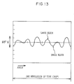
- the uniformity, i.e., the radial force variation (RFV), of the tire is related to the radial runout (RR) of the tire and a force (rigidity) occurring when the tire rotates.
- the nonuniformity of the tread gage substantially affects the aspect of the radial runout (RR) of the tire (i.e., the more nonuniform the gage is, the greater the runout becomes, and the larger the radial force (RF) of the tire becomes).
- the regularity of the irregular pitch has a bearing on the pattern component of the uniformity, i.e., the radial force variation (RFV).
- the pattern component of the uniformity (RFV) can be reduced (i.e., the amplitude of the waveform can be reduced) by arranging the irregular pitches in a irregular manner.
- tires having poor uniformity are sometimes corrected and improved by shaving off convex portions on the outer periphery of the tire.
- the size of the pattern block affects the uniformity.
- the compression and elasticity vary according to the size of the pattern block, and the change in the modulus of compressibility and elasticity affects the uniformity.
- E E0 (1 + K ⁇ L2)
- Formula (12) where K is a constant, and L is a circumferential dimension of the block.
- Formula (12) is derived as follows.
- the block is a rectangular prism
- the transverse dimension of the tire is a
- the circumferential dimension of the tire is L
- the total surface area is S
- the pressurized cross-sectional area becomes a ⁇ L
- a component (a pattern factor) is present which produces circumferential nonuniformity in both the tire runout and rigidity due to the variation of the pattern pitch in one revolution of the tire. Consequently, the situation is such that there has been no effective means of solution.
- Another object of the present invention is to provide a pneumatic tire which is manufactured by the above-described method.
- a method of manufacturing a pneumatic tire having at least one of a group of two or more kinds of island-like blocks having mutually different circumferential dimensions and a group of two or more kinds of blocks which are each defined by adjacent lug grooves of a plurality of lug grooves arranged in a circumferential row and have mutually different circumferential dimensions, characterized in that one of a linear rigidity-lowering portion and a rigidity-lowering recess is formed in at least one of each of the island-like blocks whose circumferential dimensions are relatively large among the island-like blocks and each of the blocks whose circumferential dimensions are relatively large among the blocks defined by the adjacent lug grooves.
- the linear rigidity-lowering portion in the above-described method is formed in the pneumatic tire after vulcanization.
- a linear rigidity-lowering portion is formed in each of the island-like blocks whose circumferential dimensions are relatively large among the island-like blocks and/or each of the blocks whose circumferential dimensions are relatively large among the blocks defined by the adjacent lug grooves.
- the rigidity-lowering portion is formed in the large island-like blocks and/or the large blocks defined by the adjacent lug grooves (these blocks affect the uniformity), it is possible to lower the modulus of compressibility and elasticity of the large block portions, and to reduce the difference in rigidity of the island-like blocks or the blocks between the adjacent lug grooves in the circumferential direction. Consequently, it is possible to manufacture a pneumatic tire excelling in uniformity.
- the linear rigidity-lowering portion suffices if it is capable of lowering the rigidity of the block portion, and may be formed by a recess.
- This rigidity-lowering recess may be provided with a desired cross-sectional configuration and a desired configuration of its opening. However, to prevent the deterioration of the pattern noise, a slit or the like is preferable.
- the rigidity-lowering portion may be provided with a configuration of an elongated hole.
- the rigidity-lowering portion is formed in the pneumatic tire after vulcanisation, the rigidity-lowering portion can be formed by selecting portions for which the modulus of compressibility and elasticity (rigidity) needs to be lowered. Accordingly, it is possible to form the rigidity-lowering portions by selecting only the pneumatic tires having poor uniformity, thereby making it possible to improve the uniformity of the pneumatic tires having poor uniformity.
- Fig. 1 shows a tread pattern (one side of the tire) of a pneumatic tire 10 (tire size: 235/45 ZR 17) in accordance with the first embodiment of the present invention. It should be noted that since the internal structure of this pneumatic tire 10 is similar to the structure of an ordinary radial tire, a description thereof will be omitted.
- a circumferential groove 14 is provided at a tread center CL serving as an equatorial plane of the tire.
- a circumferential groove 16 is provided on either side in the transverse direction of the tire (in the direction of arrow W in Fig. 1) with this circumferential groove 14 as a center.
- a circumferential groove 18 is provided on each outer side, as viewed in the transverse direction of the tire, of the circumferential groove 16.
- a plurality of inclined grooves 20 are formed in the tread 12 on either side of the tread center CL.
- a longitudinal end of each of these inclined grooves 20 is connected to a shoulder 22, and the other longitudinal end thereof terminates immediately before reaching the circumferential groove 14.
- Each of the inclined grooves 20 in the ground contacting portion of the tire (in the zone indicated by arrow SE in Fig. 1) is inclined such that the tread center CL side thereof is located more on the treading side in the rotating direction of the tire (on the side in the direction of arrow A in Fig. 1) than the shoulder side thereof.
- An angle of intersection of the inclined groove 20 with respect to the circumferential direction of the tire is set in such a manner as to become gradually smaller toward the tire tread center CL side.
- the direction of inclination of the inclined groove 20 is oriented in the opposite direction in a zone which is located outwardly of an end of the ground contacting portion of the tire, as viewed in the transverse direction of the tire. It should be noted that the arrow A also indicates the direction of rotation of the tire.
- a land portion located between the circumferential groove 16 and the circumferential groove 18 is divided into a plurality of first blocks 24 in a circumferential row by means of the inclined grooves 20. Also, a land portion located outwardly of the circumferential groove 18, as viewed in the transverse direction of the tire, is similarly divided into a plurality of second blocks 26 in a circumferential row by means of the inclined grooves 20.
- these first blocks 24 and the second blocks 26 are arranged in the form of sixth harmonic pattern design, and plasters 28 of a mold for forming the first blocks 24 and the second blocks 26 are arranged as shown in Fig. 2.
- large values indicate plasters for molding large blocks having long circumferential dimensions
- small values indicate plasters for molding small blocks having short circumferential dimensions.
- the inner row shows a lower mold half, while the outer row shows an upper mold half.
- the arrangement of the plasters 28 of the upper mold half and the arrangement of the plasters 28 of the lower mold half are offset from each other by predetermined pitches in the circumferential direction, so as to uniformalize the pattern noise generated by the tread 12.
- the circumferential dimension of a second block 26A having the longest circumferential dimension among the second blocks 26 is 35 mm.
- the circumferential dimension of a second block 26E having the shortest circumferential dimension is 22 mm.
- the ratio of the circumferential dimension is set to be substantially 7 : 8 : 9 : 10 : 11 in that order starting with the smallest block.
- one which is adjacent to the block having a long circumferential dimension is provided with a large groove width, while one which is adjacent to the block having a short circumferential dimension is provided with a small groove width.
- the inclined grooves 20 are thus arranged such that the negative ratio becomes uniform in the circumferential direction of the tire.
- a recess for lowering rigidity is preferably provided at a block portion which produces rigidity and is located at a tire shoulder-side hump that largely influences the relative magnitude of the radial force (RF) of the tire and is subjected to high ground contact pressure.
- the rigidity-lowering recess serving as a rigidity-lowering portion may be provided at a position other than the tire shoulder-side hump, insofar as the portion of the tread at that position has high ground contact pressure and largely influences the relative magnitude of the radial force.
- the rigidity-lowering recess should preferably be formed in such a manner as to not deteriorate the pattern noise.
- a slit 30 serving as the rigidity-lowering recess is formed in central portions, as viewed in the circumferential direction of the tire, of the second block 26A whose circumferential dimension is the longest and a second block 26B whose circumferential dimension is the second longest among the second blocks 26.
- the slit 30 extends substantially in the radial direction of the tire (in the direction of arrow W) in the circumferentially central portions of the ground contacting portions of the second blocks 26A and 26B.
- the longitudinal direction of the slit 30 is set substantially in the transverse direction of the tire (in the direction of arrow W in Fig. 3A)
- the term "transverse” means the transverse direction of the tire.
- the slit length R' is 30% to 95% of the circumferential length R of the ground contacting portion of the block
- the slit width R'' is 0.3% to 15% of the transverse length P of the ground contacting portion of the block
- the slit depth S' is 25% to 100% of the depth S of each of the adjacent grooves (in this embodiment, the inclined grooves 20) which define the circumferential length of the ground contacting portion of the block.
- each first block 24 an elongated groove 32 extending in the circumferential direction of the tire is formed in each first block 24.
- these slits 30 As a method of forming these slits 30, it is possible to cite, for example, a method in which the slits 30 are formed in the vulcanization-molded tire by a regroover (a commercially available grooving tool). However, the method of forming the slits 30 is not confined to the aforementioned forming method, and it goes without saying that the slits 30 may be formed by other known methods.
- the slits 30 are formed in the shoulder-side large blocks which are subjected to high ground contact pressure, i.e., the second block 26A whose circumferential dimension is the longest and a second block 26B whose circumferential dimension is the second longest among the second blocks 26, as described above. Accordingly, there ceases to be a difference in rigidity between the large blocks and the small blocks, with the result that the uniformity of the pneumatic tire 10 becomes excellent.
- the widths, lengths, and depths of the slits 30 are determined in correspondence with the sizes of the blocks (in correspondence with the relative rigidity of the blocks) by applying the method of manufacturing a pneumatic tire in accordance with the present invention, it is possible to manufacture a pneumatic tire having excellent uniformity which has hitherto been unobtainable.
- the uniformity is sometimes corrected and improved by shaving off convex portions on the outer periphery of the tire, there is no need to shave off the outer periphery of the tire in the method of manufacturing a pneumatic tire in accordance with the present invention, so that there is no such disadvantages as defacing the pattern and changing the pattern noise.
- the slits 30 are post-processed in correspondence with the rigidity of the blocks, it is possible to select and correct only the tires which have been finished with poor uniformity (RFV).
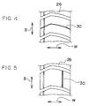
- Figs. 4 to 11 show other embodiments of the slit 30.
- the slit 30 having a fixed slit width is formed substantially in the transverse direction (in the direction of arrow W) in such a manner as to divide the second block 26.
- the slit 30 having a fixed slit width is formed substantially in the circumferential direction (in the direction of arrow B) in such a manner as to divide the second block 26.
- a plurality of slits 30 having different slit widths and lengths are formed in a portion of the second block 26 where the ground contact pressure is high, the slits 30 being formed in parallel with each other and substantially in the transverse direction (in the direction of arrow W).
- a slit 30a having a length and a depth which are larger than those of one slit 30 is superposed on that slit 30.
- a plurality of slits 30 having different slit widths and lengths are formed in parallel with each other and substantially in the circumferential direction (in the direction of arrow B).
- the slit 30a having a length and a depth which are larger than those of one slit 30 is superposed on that slit 30.
- a plurality of slits 30 having different slit widths and lengths are formed in the transverse direction and in the circumferential direction.
- slit 30 which divides the second block 26 into a circumferential row of segments and the slits 30 having different slit widths and lengths and formed on both sides of that slit 30 in such a manner as to extend substantially in the transverse direction.
- slit 30 which divides the second block 26 into a transverse row of segments and the slits 30 having different slit widths and lengths and formed on both sides of that slit 30 in such a manner as to extend in the circumferential direction.
- slit 30 which divides the second block 26 into a transverse row of segments and two slits 30 intersecting that slit 30 and formed on both sides of that slit 30 in such a manner as to extend in the circumferential direction.
- the slits 30 serving as rigidity-lowering recesses are formed in the completely independent island-like blocks
- the present invention is not limited to the same.
- the slits may be formed in blocks whose circumferential dimensions are relatively large in a pneumatic tire in which a plurality of lug grooves are arranged in a circumferential row and which are provided with two or more kinds of blocks of mutually different circumferential dimensions between adjacent lug grooves.
- slits were formed in the blocks of pneumatic tires, and the effect of the formation of the slits on the uniformity was examined.
- pneumatic tires in which the slits were not formed were prepared.
- RF of the pneumatic tire in a state in which the slits were not formed was measured.
- the slits based on the specifications shown in Table 1 were formed in blocks having the longest circumferential dimension and blocks having the second longest circumferential dimension, and an amount of change (unit: kg) in RF due to the formation of the slits was examined for the respective tires.
- Example 1 and the tire of Example 2 in Table 1 were provided with slits whose configurations were the same as that shown in Fig. 1 (various dimensions are listed in Table 1).
- the tire of Example 3 and the tire of Example 4 were provided with slits whose configurations were the same as that shown in Fig. 4 (various dimensions are also listed in Table 1).
- the tire of Example 5 and the tire of Example 6 were provided with slits whose configurations were the same as that shown in Fig. 5 (various dimensions are also listed in Table 1).
- a method of manufacturing a pneumatic tire having at least one of a group of two or more kinds of island-like blocks having mutually different circumferential dimensions and a group of two or more kinds of blocks which are each defined by adjacent lug grooves of a plurality of lug grooves arranged in a circumferential row and have mutually different circumferential dimensions, wherein a linear rigidity-lowering portion is formed in at least one of each of the island-like blocks whose circumferential dimensions are relatively large among the island-like blocks and each of the blocks whose circumferential dimensions are relatively large among the blocks defined by the adjacent lug grooves.
Landscapes
- Engineering & Computer Science (AREA)
- Mechanical Engineering (AREA)
- Tires In General (AREA)
Applications Claiming Priority (2)
| Application Number | Priority Date | Filing Date | Title |
|---|---|---|---|
| JP28001/93 | 1993-02-17 | ||
| JP5028001A JPH06239106A (ja) | 1993-02-17 | 1993-02-17 | 空気入りタイヤの製造方法 |
Publications (1)
| Publication Number | Publication Date |
|---|---|
| EP0612631A1 true EP0612631A1 (de) | 1994-08-31 |
Family
ID=12236572
Family Applications (1)
| Application Number | Title | Priority Date | Filing Date |
|---|---|---|---|
| EP94102407A Withdrawn EP0612631A1 (de) | 1993-02-17 | 1994-02-17 | Verfahren zur Herstellung von Reifen |
Country Status (2)
| Country | Link |
|---|---|
| EP (1) | EP0612631A1 (de) |
| JP (1) | JPH06239106A (de) |
Cited By (9)
| Publication number | Priority date | Publication date | Assignee | Title |
|---|---|---|---|---|
| US5824169A (en) * | 1995-01-20 | 1998-10-20 | The Goodyear Tire & Rubber Company | Pneumatic tire having improved wear properties |
| EP0847878A3 (de) * | 1996-12-12 | 1999-09-01 | Continental Aktiengesellschaft | Fahrzeugreifen mit einer Lauffläche mit Einschnitten |
| US6123130A (en) * | 1997-11-11 | 2000-09-26 | Bridgestone/Firestone, Inc. | Tire having improved wet stopping capability |
| EP1065075A1 (de) * | 1999-06-28 | 2001-01-03 | Société de Technologie Michelin | Laufflächenprofil geeignet zum Begrenzen des durch das Laufen des Reifens erzeugten Geräusches |
| US6230112B1 (en) | 1996-12-27 | 2001-05-08 | Bridgestone Corporation | Pneumatic tire designing method |
| EP1190871A3 (de) * | 2000-04-25 | 2002-07-10 | Continental Aktiengesellschaft | Fahrzeugreifen mit Feineinschnitt in der Lauffläche, Vulkanisationsform zur Herstellung eines solchen Reifens und Lamelle zum Einsetzen in eine solche Vulkanisationsform |
| EP1764236A1 (de) * | 2005-09-15 | 2007-03-21 | Sumtiomo Rubber Industries Ltd | Luftreifen |
| EP1630006A3 (de) * | 2000-01-26 | 2007-11-07 | Bridgestone Corporation | Luftreifen |
| US20110198005A1 (en) * | 2008-10-31 | 2011-08-18 | The Yokohama Rubber Co., Ltd. | Pneumatic tire |
Families Citing this family (5)
| Publication number | Priority date | Publication date | Assignee | Title |
|---|---|---|---|---|
| JP2004210133A (ja) * | 2002-12-27 | 2004-07-29 | Yokohama Rubber Co Ltd:The | 空気入りタイヤ、その製造方法および成形金型 |
| JP4935507B2 (ja) * | 2007-06-04 | 2012-05-23 | 横浜ゴム株式会社 | 空気入りタイヤ |
| JP4935508B2 (ja) * | 2007-06-04 | 2012-05-23 | 横浜ゴム株式会社 | 空気入りタイヤ |
| JP6411947B2 (ja) * | 2015-05-26 | 2018-10-24 | 株式会社ブリヂストン | タイヤ |
| EP4331867B1 (de) * | 2022-08-29 | 2025-03-12 | Venturi Lab SA | Verformbares rad mit nicht-pneumatischer lastaufnahme für bedingungen wie auf dem mond und dem mars |
Citations (8)
| Publication number | Priority date | Publication date | Assignee | Title |
|---|---|---|---|---|
| US4327792A (en) * | 1978-02-14 | 1982-05-04 | The Goodyear Tire & Rubber Company | Spreading noise generated by load supporting elements |
| JPS60128005A (ja) * | 1983-12-14 | 1985-07-08 | Sumitomo Rubber Ind Ltd | タイヤ及びその成型用金型 |
| JPS6127708A (ja) * | 1984-07-16 | 1986-02-07 | Sumitomo Rubber Ind Ltd | 空気入りタイヤ |
| EP0192911A1 (de) * | 1985-02-26 | 1986-09-03 | The Goodyear Tire & Rubber Company | Luftreifen |
| US4649975A (en) * | 1984-06-30 | 1987-03-17 | The Yokohama Rubber Co., Ltd. | Pneumatic tire tread |
| JPH01289705A (ja) * | 1988-05-17 | 1989-11-21 | Bridgestone Corp | ノイズを低減した空気入りタイヤ |
| FR2659275A1 (fr) * | 1990-03-12 | 1991-09-13 | Uniroyal Englebert Gmbh | Pneumatique de vehicule du type a structure radicale. |
| US5269357A (en) * | 1991-07-09 | 1993-12-14 | Uniroyal Goodrich Tire Company | Reduced noise generating tread pattern for a tire |
-
1993
- 1993-02-17 JP JP5028001A patent/JPH06239106A/ja active Pending
-
1994
- 1994-02-17 EP EP94102407A patent/EP0612631A1/de not_active Withdrawn
Patent Citations (8)
| Publication number | Priority date | Publication date | Assignee | Title |
|---|---|---|---|---|
| US4327792A (en) * | 1978-02-14 | 1982-05-04 | The Goodyear Tire & Rubber Company | Spreading noise generated by load supporting elements |
| JPS60128005A (ja) * | 1983-12-14 | 1985-07-08 | Sumitomo Rubber Ind Ltd | タイヤ及びその成型用金型 |
| US4649975A (en) * | 1984-06-30 | 1987-03-17 | The Yokohama Rubber Co., Ltd. | Pneumatic tire tread |
| JPS6127708A (ja) * | 1984-07-16 | 1986-02-07 | Sumitomo Rubber Ind Ltd | 空気入りタイヤ |
| EP0192911A1 (de) * | 1985-02-26 | 1986-09-03 | The Goodyear Tire & Rubber Company | Luftreifen |
| JPH01289705A (ja) * | 1988-05-17 | 1989-11-21 | Bridgestone Corp | ノイズを低減した空気入りタイヤ |
| FR2659275A1 (fr) * | 1990-03-12 | 1991-09-13 | Uniroyal Englebert Gmbh | Pneumatique de vehicule du type a structure radicale. |
| US5269357A (en) * | 1991-07-09 | 1993-12-14 | Uniroyal Goodrich Tire Company | Reduced noise generating tread pattern for a tire |
Non-Patent Citations (3)
| Title |
|---|
| DATABASE WPI Week 9033, Derwent World Patents Index; AN 86-69162 * |
| PATENT ABSTRACTS OF JAPAN vol. 14, no. 71 (M - 933)<4014> 9 February 1990 (1990-02-09) * |
| PATENT ABSTRACTS OF JAPAN vol. 9, no. 286 (M - 429) 13 November 1985 (1985-11-13) * |
Cited By (15)
| Publication number | Priority date | Publication date | Assignee | Title |
|---|---|---|---|---|
| US5824169A (en) * | 1995-01-20 | 1998-10-20 | The Goodyear Tire & Rubber Company | Pneumatic tire having improved wear properties |
| EP0847878A3 (de) * | 1996-12-12 | 1999-09-01 | Continental Aktiengesellschaft | Fahrzeugreifen mit einer Lauffläche mit Einschnitten |
| US6531012B2 (en) * | 1996-12-27 | 2003-03-11 | Bridgestone Corporation | Pneumatic tire designing method |
| US6230112B1 (en) | 1996-12-27 | 2001-05-08 | Bridgestone Corporation | Pneumatic tire designing method |
| US6123130A (en) * | 1997-11-11 | 2000-09-26 | Bridgestone/Firestone, Inc. | Tire having improved wet stopping capability |
| US6484773B1 (en) * | 1999-06-28 | 2002-11-26 | Michelin Recherche Et Technique | Tread pattern which reduces the running noise of a tire |
| EP1065075A1 (de) * | 1999-06-28 | 2001-01-03 | Société de Technologie Michelin | Laufflächenprofil geeignet zum Begrenzen des durch das Laufen des Reifens erzeugten Geräusches |
| EP1630006A3 (de) * | 2000-01-26 | 2007-11-07 | Bridgestone Corporation | Luftreifen |
| EP1630005A3 (de) * | 2000-01-26 | 2007-11-07 | Bridgestone Corporation | Luftreifen |
| EP1190871A3 (de) * | 2000-04-25 | 2002-07-10 | Continental Aktiengesellschaft | Fahrzeugreifen mit Feineinschnitt in der Lauffläche, Vulkanisationsform zur Herstellung eines solchen Reifens und Lamelle zum Einsetzen in eine solche Vulkanisationsform |
| EP1764236A1 (de) * | 2005-09-15 | 2007-03-21 | Sumtiomo Rubber Industries Ltd | Luftreifen |
| CN100464996C (zh) * | 2005-09-15 | 2009-03-04 | 住友橡胶工业株式会社 | 充气轮胎 |
| US7757735B2 (en) | 2005-09-15 | 2010-07-20 | Sumitomo Rubber Industries, Ltd. | Pneumatic tire having buttress part |
| US20110198005A1 (en) * | 2008-10-31 | 2011-08-18 | The Yokohama Rubber Co., Ltd. | Pneumatic tire |
| US8950453B2 (en) * | 2008-10-31 | 2015-02-10 | The Yokohama Rubber Co., Ltd. | Pneumatic tire |
Also Published As
| Publication number | Publication date |
|---|---|
| JPH06239106A (ja) | 1994-08-30 |
Similar Documents
| Publication | Publication Date | Title |
|---|---|---|
| EP1245410B1 (de) | Verfahren zur Gestaltung von zyklischen Profilmustern in einer Reifenlauffläche | |
| JP2802200B2 (ja) | タイヤ | |
| KR100306731B1 (ko) | 타이어의트레드소음을줄이기위한다중트레드형상 | |
| EP0698511B1 (de) | Luftreifen | |
| EP1669218B1 (de) | Fahrzeugluftreifen | |
| US5769990A (en) | Method of making tire with tire tread pitch bands | |
| JPS60240507A (ja) | 低騒音マルチサイピングタイヤ | |
| JPH06239106A (ja) | 空気入りタイヤの製造方法 | |
| US5974872A (en) | Pitch arrangement evaluation system of tread pattern of pneumatic tire | |
| US5658409A (en) | Low noise tire | |
| US7950426B2 (en) | Tread blocks having reduced edge stiffness | |
| US6578612B1 (en) | Pneumatic radial tire having six block rows | |
| US6796349B2 (en) | Pneumatic tire including protrusion dividing groove space of main groove having groove width narrowed during inflation | |
| JPS6127708A (ja) | 空気入りタイヤ | |
| JPH09142105A (ja) | 空気入りタイヤ | |
| JP3559060B2 (ja) | 空気入りタイヤ | |
| JPH04244402A (ja) | 騒音を低減した空気入りタイヤ | |
| JPH1178425A (ja) | 空気入りタイヤ | |
| JPH048607A (ja) | 高速走行用空気入りタイヤ | |
| JP3759826B2 (ja) | 空気入りタイヤ及びモールド | |
| EP0752326A2 (de) | Luftreifen | |
| JP2002002234A (ja) | 空気入りタイヤ | |
| JPH1178423A (ja) | 空気入りタイヤ | |
| JPH02109705A (ja) | 空気入りタイヤ | |
| JP2000255216A (ja) | 空気入りラジアルタイヤ |
Legal Events
| Date | Code | Title | Description |
|---|---|---|---|
| PUAI | Public reference made under article 153(3) epc to a published international application that has entered the european phase |
Free format text: ORIGINAL CODE: 0009012 |
|
| AK | Designated contracting states |
Kind code of ref document: A1 Designated state(s): DE ES FR GB IT |
|
| STAA | Information on the status of an ep patent application or granted ep patent |
Free format text: STATUS: THE APPLICATION IS DEEMED TO BE WITHDRAWN |
|
| 18D | Application deemed to be withdrawn |
Effective date: 19950301 |