EP0612680A1 - Alimentation de feuilles réceptrices et appareil d'alimentation - Google Patents
Alimentation de feuilles réceptrices et appareil d'alimentation Download PDFInfo
- Publication number
- EP0612680A1 EP0612680A1 EP94101445A EP94101445A EP0612680A1 EP 0612680 A1 EP0612680 A1 EP 0612680A1 EP 94101445 A EP94101445 A EP 94101445A EP 94101445 A EP94101445 A EP 94101445A EP 0612680 A1 EP0612680 A1 EP 0612680A1
- Authority
- EP
- European Patent Office
- Prior art keywords
- sheet
- stack
- air
- feeding apparatus
- supply
- Prior art date
- Legal status (The legal status is an assumption and is not a legal conclusion. Google has not performed a legal analysis and makes no representation as to the accuracy of the status listed.)
- Granted
Links
Images



Classifications
-
- B—PERFORMING OPERATIONS; TRANSPORTING
- B65—CONVEYING; PACKING; STORING; HANDLING THIN OR FILAMENTARY MATERIAL
- B65H—HANDLING THIN OR FILAMENTARY MATERIAL, e.g. SHEETS, WEBS, CABLES
- B65H3/00—Separating articles from piles
- B65H3/46—Supplementary devices or measures to assist separation or prevent double feed
- B65H3/48—Air blast acting on edges of, or under, articles
-
- B—PERFORMING OPERATIONS; TRANSPORTING
- B65—CONVEYING; PACKING; STORING; HANDLING THIN OR FILAMENTARY MATERIAL
- B65H—HANDLING THIN OR FILAMENTARY MATERIAL, e.g. SHEETS, WEBS, CABLES
- B65H3/00—Separating articles from piles
- B65H3/08—Separating articles from piles using pneumatic force
- B65H3/12—Suction bands, belts, or tables moving relatively to the pile
- B65H3/124—Suction bands or belts
- B65H3/128—Suction bands or belts separating from the top of pile
Definitions
- the present invention relates in general to sheet handling apparatus for reproduction apparatus for example, and more particularly to a receiver sheet supply and feed apparatus, including a vacuum corrugation belt feeder and a positive air pressure separator.
- receiver material such as plain bond paper or transparencies.
- receiver sheets are stored in a stack and fed seriatim when copies are to be reproduced.
- the sheet feeder for the reproduction apparatus must be able to handle a wide range of sheet types and sizes reliably and without damage. Sheets must be fed individually; that is, without misfeeds or multi-feeds.
- Reproduction apparatus sheet feeders are typically of two types, vacuum feeders or friction feeders.
- One type of vacuum feeder is shown in US -A-4,169,676.
- This vacuum feeder commonly referred to as an oscillating vacuum feeder, includes an oscillating tube through which vacuum is applied to tack a sheet to the surface of the tube (sheet acquisition) for withdrawal from the sheet supply stack.
- Nip rollers in cooperative relation with bearings on the tube downstream of sheet acquisition zone in a sheet feeding direction, urge a separated sheet from the sheet supply stack along a feed path away from the supply stack. While such feeder is considered to be highly effective, it does have some limitations in feeding extremely light or heavyweight papers. It is also noisy due to both its mechanical oscillation requirements and its need to utilize a high flow/high pressure vacuum source.
- This vacuum feeder commonly referred to as a vacuum corrugation feeder, includes a vacuum plenum for acquiring a sheet from a supply stack.
- the top sheets in the stack are levitated by flutter (positive air pressure) jets.
- Ported belts entrained about the plenum are driven to transport a sheet vacuum tacked to the belts from the supply stack.
- This type of feeder is highly efficient but is still subject to misfeeds/multi-feeds, and has certain limitations with regard to the range of types of sheet materials that can be reliably handled.
- FIG. 1 Yet another type of vacuum feeder is shown in US -A-4,184,672 and -A-4,327,906.
- This type of vacuum feeder commonly referred to as a vacuum picker or sucker, includes a plurality of cup-like structures connected to a vacuum source and movable to selectively pick up a sheet from a supply stack for transport from the stack.
- Such feeder requires a complicated mechanical arrangement to accomplish its desired pick up and transport function.
- scuff feeder includes a member (respectively shown as a belt or paddle wheel, but may also comprise a roller) which relies on frictional engagement with a sheet for removal of the sheet from a supply stack.
- Scuff feeders are of the simplest construction and are the cheapest to manufacture. However, since sheet materials exhibit a wide variation in friction characteristics, scuff feeders are the least reliable of the discussed group of feeders.
- this invention is directed to an apparatus for storing a stack of sheets in a supply hopper and reliably and efficiently feeding sheets seriatim from the sheet supply stack.
- the apparatus comprises a sheet feed head assembly including a plenum, a vacuum source in flow communication with the plenum, and a mechanism, such as a feed belt, for example, associated with the plenum for urging a sheet acquired by vacuum in a sheet feeding direction away from the sheet supply stack.
- the sheet supply stack is supported so as to maintain the topmost sheet in such stack at a predetermined level in spaced relation with respect to the urging mechanism of the sheet feed head assembly.
- a first positive air supply directs a flow of air at the sheet supply stack to levitate the top several sheets in the supply stack to an elevation enabling the topmost sheet to be acquired by vacuum from the sheet feed head assembly plenum; and a second positive air supply directs a flow of air at an acquired sheet to assure separation of any additional sheets adhering to such topmost sheet.
- the receiver sheet supply and feeding apparatus designated generally by the numeral 10, includes an open hopper 12 and an elevating platform 14 for supporting a stack of sheets.
- a sheet stack (designated by the letter S) supported on the platform 14 contains individual sheets suitable, for example, for serving as receiver sheets for having reproductions formed thereon in a copier or printer device.
- Sheets for receiving reproductions may be selected from a wide variety of materials and sizes.
- the sheets may be of a weight in the range of 13 pound bond to 140 pound index, and a size in the range of 8 x 5 inches to 11 x 17 inches.
- the sheet stack supporting platform 14 is supported within the hopper 12 for substantially vertical elevational movement by lifting mechanism L.
- the lifting mechanism L serves to raise the platform 14 to an elevation for maintaining the topmost sheet in the stack S at a predetermined level during operation of the receiver sheet supply and feeding apparatus 10, and lower the platform to permit adding sheets thereto.
- the lifting mechanism L includes a motor M1, attached to the outside of the upstanding front wall of the hopper 12 (see Fig. 1).
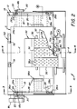
- the motor M1 rotates an output gear 16 in mesh with a gear 18a mounted on a shaft 18 extending from the upstanding front wall of the hopper 12 through the upstanding rear wall of the hopper (see Fig. 2).
- a pair of pulley mounted lifting chains 20 are respectively interconnected by gears 18b with the shaft 18 to be moved about a closed loop path when the shaft 18 is rotated by the motor M1.
- Each of the lifting chains have a link 22 extending through a slot 12a respectively in the front and rear upstanding wall of the hopper 12.
- the links 22 are connected to respective pulleys 24 mounted on a shaft 24a supported in brackets 24b extending from the underside of the platform 14 (see Fig. 3).
- Tension cables 26 are respectively connected, at the ends 26a, 26b thereof, to the front and rear upstanding wall of the hopper 12. The cables are respectively threaded over their associated pulleys 24 and under pulleys 28 mounted on a shaft 28a supported in brackets 28b extending from the underside of the platform 14.
- the sheet stack supporting platform 14 is shown in its most elevated position in solid lines, and in its lowest position in phantom.
- an appropriate signal to the motor M1 causes the motor to rotate the gear 16, either clockwise (in Fig. 1) to lower the platform 14 toward the lowest position or counterclockwise to raise the platform toward its most elevated position.
- Rotation of the gear 16 moves the lifting chains 20 in their closed loop paths imparting vertical movement to the links 22.
- This movement moves the shaft 24a, and thus the platform 14 and its brackets 24b and pulleys 24.
- the platform 14 is maintained substantially level in its movement by the action of the tension cables 26 which cooperatively move the pulleys 28 and thus the shaft 28a and brackets 28b of the platform.
- Maintaining the topmost sheet at the predetermined level is accomplished by a sheet detecting switch 80 (see Fig. 5) which controls the operation of the motor M1 for actuating the lifting mechanism L, in the manner to be explained hereinbelow, to raise the platform 14 through a predetermined increment.
- lowering of the platform 14 is usually accomplished by some externally produced signal to the motor which tells the motor to rotate for a time sufficient to bring the platform to its lowest position.
- a sheet feed head assembly is located in association with the hopper 12 so as to extend over a portion of the platform 14 in spaced relation to a sheet stack supported thereon.
- the sheet feed head assembly 30 includes a ported plenum 32 connected to a vacuum source V, and an air jet device 40 connected to a positive pressure air source P.
- a positive pressure air jet from the device 40 levitates the top several sheets in the supported sheet stack S, vacuum at the plenum 32 is effective through its ports 32p (see Fig. 4) to cause the topmost levitated sheet from the stack to thereafter be acquired at the plenum for separation from the sheet stack, and additional positive pressure air jets from the device 40 assure separation of subsequent sheets from the acquired topmost sheet.
- the lower surface 32a of the plenum 32 of the sheet feed head assembly 30 has a particularly configured shape (shown in Fig. 5) so as to provide for a specific corrugation of an acquired sheet.
- the topmost sheet contacts the outer winged portions 32b of the surface 32a.
- a minimal pressure is exerted on the cross-track marginal edges of the sheet to help in forming a controlled corrugation to the sheet.
- This establishes a consistent spacing for the center portion of the sheet from the center portion of the plenum 32.
- the access time for a sheet to be acquired at the plenum is repeatably consistent and readily predictable.
- the interactions of the plenum 32, the air jet device 40, and a front stop assure that control over the sheet as it is acquired at the plenum is never lost. Further, corrugation of the sheet contorts the sheet in an unnatural manner. Since subsequent sheets are not subjected to the same forces, at the same time, as is the topmost sheet, such subsequent sheets are unable to contort in the same manner. Accordingly, the subsequent sheets are effectively separated from the topmost sheet as it is being acquired at the plenum.
- the vacuum source V may create a flow rate in the range of approximately 35 cu. ft./min. to 60 cu. ft./min., with 47-53 cu. ft./min. being optimum.
- a valve 38 (see Fig. 5), of the bleed-off, poppet or gravity door type for example, is used to limit the vacuum level once a sheet has been acquired at the plenum 32. Limiting of the vacuum level aides in limiting air bleed through of some porous type sheet materials.
- Vacuum bleed through for a porous sheet may potentially cause the undesirable condition where a subsequent sheet will adhere to the acquired sheet and result in a multi-feed. Additionally, limiting the vacuum level reduces the amount of energy required to transport the acquired sheet forward in the sheet feed direction. That is, the vacuum induced normal forces holding the sheet to the plenum 32 are reduced so that the sheet may be more readily transported, in the manner described hereinbelow, in the feed direction with substantially less drag.
- a switch 36 for example a pressure or mechanically activated switch, is attached to the plenum to detect when a sheet has been acquired.
- a signal provided by the switch on detection of sheet acquisition is utilized to control operation of various components of the sheet feed-head assembly 30, such as timing of activations or setting of air flow levels, to optimize operation for a particular type (size) of sheet to be fed from the sheet supply and feeding 10 according to this invention.
- the sheet feed head assembly 30 additionally includes a belt mechanism 34 for transporting an acquired sheet in a feed direction (designated by the arrow A in Figs. 2 and 3) away from the sheet stack S toward a downstream location.
- the belt transport mechanism 34 has a plurality of belts 36 entrained about rollers 38 to establish a closed loop path about the plenum 32.
- the lower runs of the belts 46 are in intimate contact with the lower surface 22a of the plenum 22 (see Fig. 5).
- the acquired sheet from the sheet stack S is effectively tacked to the belts by air pressure resulting from the application of vacuum in the plenum 32 through the plenum ports 32p and the belt ports 36p.
- the belts 36 are selectively driven in a direction (counter-clockwise in Figs. 3 and 4) to remove the acquired sheet from the area above the sheet stack S and transport the sheet in the feed direction A along a travel path to a downstream transport, such as driven feed nip roller pair 50.
- the nip roller pair 50 is driven by a motor M2.
- a gear 52 is rotatably mounted on a shaft 54 supporting one roller of the nip roller pair.
- a clutch 56 is selectively activated to couple the gear 52 to the shaft 54 for rotation with the shaft.
- An intermediate gear 58 is in mesh with the gear 52 and a gear (not shown) coupled to one of the belt rollers 38. Accordingly, when the clutch 56 is activated, the belts 36 will be driven so as to feed an acquired sheet such that the acquired sheet is transported from the sheet stack S and is thereafter available for any further processing, such as receiving a reproduction from a copier or printer, for example.
- the hopper 12 incorporates a front stop 60, a rear stop 62 and side stops 64 arranged to engage the marginal edges of a sheet stack S supported on the platform 14 and accurately locate the sheet stack relative to the sheet feed head assembly 30.
- the front stop 60 additionally provides a lead edge guide for the topmost sheet in the sheet stack as it is removed from the stack for acquisition, and also serves as a retard mechanism for any sheets adhering to the topmost sheet as it is removed.
- the positive pressure air jet device 40 of the sheet feed head assembly 30 is located adjacent to the front stop 60 on the opposite side thereof from the sheet supporting platform 14. As noted above, the air jet device 40 is for the purpose of levitating the top sheets in the sheet stack S and separating subsequent sheets adhering to the topmost sheet when acquired for removal from the sheet stack.
- the positive pressure air jet device 40 includes a first air jet arrangement 42 and a second air jet arrangement 44.
- the first air jet arrangement 42 incorporates a single nozzle 42a in flow communication with a source of positive pressure air P.
- the nozzle 42a is located substantially along the center line C (see Fig. 2) of the sheet stack S, in the cross-track direction, and is aimed at the location where the top of the sheet stack will be positioned by the sheet support platform 14.
- the single nozzle 42a directs a high pressure air stream at the sheet stack, in the center of the lead edge, to fluff the top several sheets in the stack to bring the topmost sheet into association with the sheet feed head assembly 30 where it can be acquired, by vacuum, at the plenum 32.
- the cross-sectional area of the nozzle 42a of the first air jet arrangement 42 is shaped as a tear drop (see Fig. 6).
- the top portion of the tear drop is approximately 1/2 the dimension of the bottom portion so as to apply a larger amount of air at the bottom of the nozzle than at the top.
- the nozzle 42a is between .300 inch to .600 inch (in the vertical dimension), between .075 inch to .250 inch across the bottom portion of the tear drop, and between .0375 inch to .125 inch across the top portion of the tear drop.
- the location of the nozzle 42a to the sheet stack supported on the platform 14 is to have the nozzle .125 ⁇ .060) inch away from the lead edge of the sheet stack and the topmost sheet in the stack approximately .125 ( ⁇ .060) inch below the top point of the tear drop.
- the nozzle which has a substantially vertical face 42a', has an air channel that is oriented approximately 25° to 35° from the vertical.
- the top several sheets in the sheet stack S begin separation between each sheet and the topmost sheet rises, along its center line C in the feed direction A, to a controlled height above the sheet stack.
- the positive air flow through the nozzle can be pulsed from a low to a high flow rate, or may be left on at a high flow rate.
- the air flow is in the range of between 1.5 cu. ft./min. to 4.5 cu. ft./min., with 1.75 cu. ft./min. being optimum. It has been found that air volume, velocity, and sheet weight can all vary within the described limits and still provide a consistent and controlled height to the levitated topmost sheet.
- the topmost sheet will rise to the outside corrugation points of the plenum 32.
- the air flow going into the stack will ideally be allowed to proceed through the stack out the rear thereof, with some finding its way out through the sides of the stack.
- the nozzle may have a round or oval cross-section (although this may result in a somewhat degraded performance over the performance with the preferred tear drop shaped cross-section). Additionally, the nozzle may be integrally formed with the front stop 60.
- the second air jet arrangement 44 incorporates a plurality of nozzles 44a (preferably six in number) in common flow communication with the source of positive pressure air P (or, alternatively, a second separate source of pressurized air).
- the nozzles 44a are aimed at the location where the top of the sheet stack will be positioned by the sheet support platform 14, and slightly downstream of the aim point for the first air jet nozzle 42a (see Fig. 1).
- the purpose of the second air jet arrangement 44 is to separate any sheets adhering to the topmost sheet acquired by the sheet feed head assembly 30 for removal and transport from the sheet stack S.
- the nozzles 44a of the second air jet arrangement 44 are angled approximately 25° to 35° from the horizontal face of the subsequent sheets.
- the nozzles 44a have a cross-sectional area in the shape of a semicircle (see Fig. 6), and the bottom of the air streams from the respective nozzles is focused such that it is aimed within approximately .125 inch from the lead edge of the topmost sheet acquired by the plenum 32.
- the cross-sectional area of the nozzles is respectively between .0122 sq. in. and .0382 sq. in.
- the air flow for each of the plurality of nozzles 44a is, as in the case of the air flow for the nozzle 42a of the first air jet arrangement 42, in the range of between 1.5 cu.
- the total air flow is in the range of between 9-27 cu. ft./min., with 10.5 cu. ft./min. being optimum.
- the air flow may be pulsed from an off or medium flow rate to a high flow rate.
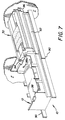
- the front stop comprises a plate 70 having a surface 70a against which the lead edge of the stack of sheets S is positioned to accurately locate the stack, in the sheet feed direction, relative to the sheet feed head assembly 20.
- the plate 70 has a pair of upstanding fingers 72.
- the fingers 72 serve to maintain the in-track position of the sheets of the stack as the sheets are levitated by the first air jet arrangement 42. That is, the topmost sheet and a number of subsequent sheets levitate, but are kept from moving forward relative to the sheet stack S by the fingers 72.
- the tops 72a of the fingers are configured to have an angle substantially equal to the corrugation of the plenum surface 32a respectively adjacent thereto. This establishes a restricted sheet passage (see Fig.
- any subsequent sheets adhering to the topmost acquired sheet will not have the proper corrugation, as explained above, and will be blocked by the fingers 72 so that they will not be able to be transported away from the sheet stack. If not for the fingers, the subsequent sheets could be dragged forward during transport of the topmost sheet by the belts 36 creating a multi-feed condition or incorrectly locating the subsequent sheets for the beginning of the next feed cycle.
- the spacing of the fingers 72 is selected to enable substantially free positive air flow from the first and second air jet arrangements 42, 44 therebetween.
- the hopper 12 also incorporates a rear stop 62.
- the rear stop 62 is necessary to prevent sheets levitated from the sheet stack S by the first air jet arrangement 42 from moving toward the rear (relative to the sheet stack) by the positive air pressure exerted on the sheets.
- the rear stop 62 is adjustably mounted (on guide rods for example) for selective positioning in the sheet feed direction A so as to positively engage the rear edge of a sheet stack, of any of a variety of dimensions in the sheet feed direction, supported on the platform 14 and engaged at its lead edge with the front stop 60.
- the rear stop 62 is also supported on an index rod 74.
- the rear stop is manually movable along the guide and index rods to a selected position corresponding to a dimension of the sheet stack in the in-track direction (measured from the front stop 60).
- the rear stop 62 is locked in the selected position by a member 62a interconnected to the rear stop by a tension spring 76.
- the spring 76 urges the lead edge of the member 62a into positive locking engagement with a selected one of a plurality of grooves 74a spaced along the index rod 74.
- Adjustment of the rear stop 62 is thus accomplished by manually moving the member 62a against the urging of the spring 76 out of association with the grooves and then sliding the stop along the index rod 74.
- the member 62a is then released and will engage a corresponding groove of the index rod 74 to lock the rear stop in the desired position.
- the rear stop 62 also includes a loading device 78, such as a leaf spring.
- the purpose of the loading device 78 is to exert a pressure on the top portion of the sheet stack S (and the levitated sheets) to assure that the sheets are maintained against the front stop 60. As such, the levitated sheets are maintained in their position relative to the sheet stack against the fingers 72 of the front stop 60.
- the positive air flow from the air jet device 40 between the levitated sheets be allowed to escape from the rear of the sheets. If the air flow were to be restricted, the corrugation of the topmost sheet will become unpredictable and thus the efficiency in acquiring the sheet by the sheet feed head assembly 30 will be substantially reduced.
- the rear stop 62 is formed as two substantially identical assemblies spaced apart on opposite sides of the supported sheet stack center line C.
- a single assembly with a large opening spanning the area through which the air flow can pass substantially unrestricted is also suitable for use with this invention.
- a sensor SN is utilized to detect the position of the rear stop 62. From the detected position, it is possible to determine the in-track dimension of the sheets in the sheet stack S and optimize timing of functions related to the feeding of sheets seriatim from the stack.
- the side stops 64 are of generally the same construction as that of the rear stop 62 (the exception being that only one of the side stops includes a loading device). Similar sensors are used to detect the positions of the side stops for determining, for example, the cross-track dimension of the sheet stack supported on the platform 14.
- the level of the topmost sheet in the stack supported on the platform 14 is maintained at a predetermined height relative to the plenum 32.
- the level is selected to be in a range where the topmost sheet, when levitated by the first air jet arrangement 42, is close enough to the plenum 32 to be readily acquired by the vacuum forces from the plenum within a repeatable time frame, and far enough away from the plenum to assure that the sheet being acquired is not pinned by the plenum. Pinning of the sheet would result in misfeeds or skew.
- the switch 80 is for the purpose of detecting the level of the topmost sheet.
- Such switch (see Fig. 5) is, for example, a pin that rides against the sheet, with very little downward pressure, at the highest level of acceptable corrugation.
- the pin is integrated into a hall effect switch so as to cause limited pressure on the sheet.
- the switch 80 is made during the feed cycle of the sheet feed head assembly 30 and read during the feed interval to effect raising of the platform 14 to maintain the proper sheet level.
- the location of the switch 80 at the highest level of acceptable corrugation is an advantage in that the switch will sense the location of sheets which may be severely curled and still not pin the sheet to the plenum.
- the switch 80 may also be used to determine the weight (thickness) of the receiver sheets being fed from any particular stack on the platform 14. Signals from the switch 80 can be interpreted to determine the number of sheets fed from the sheet stack per incremental elevation of the platform 14. Such number is directly relatable to the weight of the sheet material.
- the weight of the sheet material is a useful parameter to know when setting air (pressure or vacuum) levels for optimum operation of the sheet supply and feeding apparatus 10.
- the hopper 12 and the sheet feed head assembly 30 are cooperatively associated so as to be selectively movable either together or independently.
- the purpose of such association is to enable the hopper 12 to be readily accessed for placement of a stack of sheets therein, and to enable the entire supply and feeding apparatus 10 to be readily accessible for maintenance or jam clearance.
- the supply and feeding apparatus 10 is typically associated with a reproduction apparatus for providing sheets thereto for enabling copies to be made on such sheets.
- the supply and feeding apparatus 10 is normally precisely located at an operative position within the frame of the reproduction apparatus in a predetermined alignment to assure feeding of sheets along an established feed path.
- the various components of the apparatus 10 must be readily accessible by an operator. Generally, this requires that the apparatus 10 be movable to a position remote from the operative position (e.g., external to the reproduction apparatus).
- the supply and feeding apparatus 10 is mounted on slide rails 90 which are supported within the frame F of an exemplary reproduction apparatus.
- the sheet feed head assembly 30 is mounted in a slide rail 92, and on roller assembly 94, supported by the hopper 12.
- a passive latch 96 such as a magnet or spring detent assembly, for example, releasably couples the sheet feed head assembly 20 to the frame F of the reproduction apparatus. The strength of the passive latch 96 is set to assure that it will normally overcome the forces of the hopper 12 moving in the slide rails 90 to hold the assembly 30 at the operative position.
- the sheet feed head assembly 30 is retained within the apparatus, with the roller assembly serving to help in the support of the sheet feed head assemby.
- the interior of the hopper 12 is readily accessible for loading of the sheet stack on the platform 14.
- the sheet feed head assembly 30 can be manually urged to overcome the passive latch such that the assembly moves on the slide rail 92 and roller assembly 94 to the remote location with the hopper 12 for ready access.
- the hopper 12 has a tapered pin 98 extending from the upstanding wall away from the front of the reproduction apparatus.
- the pin 98 is aligned with a hole 98a defined in the sheet feed head assembly 30. Receipt of the pin 98 in the hole 98a assures the accurate alignment of the sheet feed head assembly with the hopper to establish a unitary arrangement. On return to the operative position within the reproduction apparatus, the hopper 12 and the sheet feed head assembly 30 are moved substantially together.
Landscapes
- Engineering & Computer Science (AREA)
- Mechanical Engineering (AREA)
- Sheets, Magazines, And Separation Thereof (AREA)
Applications Claiming Priority (2)
| Application Number | Priority Date | Filing Date | Title |
|---|---|---|---|
| US23032 | 1979-03-23 | ||
| US08/023,032 US5344133A (en) | 1993-02-25 | 1993-02-25 | Vacuum belt feeder having a positive air pressure separator and method of using a vacuum belt feeder |
Publications (2)
| Publication Number | Publication Date |
|---|---|
| EP0612680A1 true EP0612680A1 (fr) | 1994-08-31 |
| EP0612680B1 EP0612680B1 (fr) | 1997-05-21 |
Family
ID=21812732
Family Applications (1)
| Application Number | Title | Priority Date | Filing Date |
|---|---|---|---|
| EP94101445A Expired - Lifetime EP0612680B1 (fr) | 1993-02-25 | 1994-02-01 | Alimentation de feuilles réceptrices et appareil d'alimentation |
Country Status (4)
| Country | Link |
|---|---|
| US (1) | US5344133A (fr) |
| EP (1) | EP0612680B1 (fr) |
| JP (1) | JP3490492B2 (fr) |
| DE (1) | DE69403239T2 (fr) |
Cited By (7)
| Publication number | Priority date | Publication date | Assignee | Title |
|---|---|---|---|---|
| GB2276871B (en) * | 1993-04-07 | 1997-04-23 | Licentia Gmbh | Method of and apparatus for separately removing flat articles from a stack |
| WO1997036811A1 (fr) * | 1996-03-29 | 1997-10-09 | Siemens Aktiengesellschaft | Dispositif et procede pour empecher des enlevements en double |
| EP0811570A3 (fr) * | 1996-06-08 | 1998-03-04 | Horizon International Inc. | Dispositif d'alimentation de papier et son rotor |
| EP1127818A3 (fr) * | 2000-02-25 | 2003-01-02 | NexPress Solutions LLC | Dispositif de séparation d'une feuille au sommet d'une pile de réserve à l'aide de moyens de soufflage d'air |
| US6629692B2 (en) | 2000-02-25 | 2003-10-07 | Nexpress Solutions Llc | Device for separating an uppermost sheet from a supply stack by means of air blowers |
| WO2004037693A3 (fr) * | 2002-10-28 | 2004-06-24 | Oce Printing Systems Gmbh | Dispositif d'alimentation feuille par feuille pour imprimante |
| EP2325119A4 (fr) * | 2008-09-16 | 2013-08-07 | Konica Minolta Business Tech | Appareil d alimentation en feuilles et système de formation d image |
Families Citing this family (39)
| Publication number | Priority date | Publication date | Assignee | Title |
|---|---|---|---|---|
| US5454556A (en) * | 1994-01-06 | 1995-10-03 | Xerox Corporation | Curl detection through pneumatic acquisition sensing |
| US5876030A (en) * | 1996-05-03 | 1999-03-02 | Eastman Kodak Company | Apparatus for facilitating handling tab stock in a top feed vacuum corrugated feeder |
| US5707056A (en) * | 1995-09-28 | 1998-01-13 | Xerox Corporation | Variable ratio feedhead plenum |
| US5823527A (en) * | 1995-12-29 | 1998-10-20 | Eastman Kodak Company | Control for a sheet stack supporting platform |
| US5988629A (en) * | 1996-09-30 | 1999-11-23 | Eastman Kodak Company | Control for a sheet stack supporting platform |
| JP3349360B2 (ja) * | 1996-09-13 | 2002-11-25 | シャープ株式会社 | 給紙装置 |
| US5921540A (en) * | 1998-06-01 | 1999-07-13 | Xerox Corporation | Vacuum corrugation feeder with a retractable corrugator |
| US6412769B1 (en) * | 1999-06-28 | 2002-07-02 | Kyocera Mita Corporation | Paper feeder |
| US6290225B1 (en) * | 1999-11-23 | 2001-09-18 | Xerox Corporation | Systems and methods for dynamically setting stack height and sheet acquisition time |
| US6543759B2 (en) * | 2000-02-23 | 2003-04-08 | Kyocera Mita Corporation | Paper feeder for use in image forming apparatus |
| US6270075B1 (en) * | 2000-06-26 | 2001-08-07 | Xerox Corporation | Vacuum transport for use in a xerographic printer |
| US7007944B1 (en) * | 2000-10-14 | 2006-03-07 | Eastman Kodak Company | Pulsed airknife control for a vacuum corrugated feed supply |
| US6554269B1 (en) * | 2000-10-14 | 2003-04-29 | Heidelberger Druckmashinen Ag | Airknife and vacuum control changes to improve sheet acquisition for a vacuum corrugated feed supply |
| US6698747B2 (en) | 2001-02-06 | 2004-03-02 | Heidelberger Druckmaschinen Ag | Method and system for providing sheet stack level control |
| US6746011B2 (en) * | 2002-06-07 | 2004-06-08 | Xerox Corporation | Sheet separating and feeding with variable position stack edge fluffing |
| US6669187B1 (en) * | 2002-06-13 | 2003-12-30 | Xerox Corporation | Rear jet air knife |
| US6994340B2 (en) * | 2002-09-12 | 2006-02-07 | Xerox Corporation | Sheet feeding apparatus having an air fluffer |
| EP1403200A3 (fr) * | 2002-09-26 | 2005-04-06 | Eastman Kodak Company | Procédé pour côntroler l'avance d'une pile dans un appareil de reproduction |
| US20070096387A1 (en) * | 2002-09-26 | 2007-05-03 | Sciurba Thomas K | Method for controlling stack-advancing in a reproduction apparatus |
| US20050212198A1 (en) * | 2004-03-29 | 2005-09-29 | Eastman Kodak Company | Method of operating a vacuum corrugated belt feeder to improve sheet acquisition from a feed supply |
| US20050280198A1 (en) * | 2004-06-21 | 2005-12-22 | Eastman Kodak Company | Devices and methods for flipping a sheet with blowing assistance |
| ITBO20050678A1 (it) * | 2005-11-07 | 2006-02-06 | Gd Spa | Unita' di alimetazione di fogli ad una linea di incarto |
| JP4948243B2 (ja) * | 2007-04-12 | 2012-06-06 | キヤノン株式会社 | シート給送装置及び画像形成装置 |
| JP5380002B2 (ja) * | 2008-05-22 | 2014-01-08 | コニカミノルタ株式会社 | 給紙装置及びこれを備えた画像形成装置 |
| JP5146173B2 (ja) * | 2008-07-25 | 2013-02-20 | コニカミノルタビジネステクノロジーズ株式会社 | 画像形成装置 |
| US8752831B2 (en) * | 2008-10-06 | 2014-06-17 | Xerox Corporation | Systems and methods for controlling substrate flatness in printing devices using the flow of air |
| US8186675B2 (en) * | 2008-10-06 | 2012-05-29 | Xerox Corporation | Systems and methods for controlling substrate flatness in printing devices using vacuum and/or the flow of air |
| JP5298794B2 (ja) * | 2008-11-18 | 2013-09-25 | コニカミノルタ株式会社 | 給紙装置及び画像形成装置 |
| JP5233633B2 (ja) * | 2008-12-11 | 2013-07-10 | コニカミノルタビジネステクノロジーズ株式会社 | 給紙装置、給紙ユニット及び画像形成装置 |
| JP2010163254A (ja) * | 2009-01-16 | 2010-07-29 | Konica Minolta Business Technologies Inc | 給紙装置 |
| US7957657B2 (en) * | 2009-02-12 | 2011-06-07 | Xerox Corporation | Universal module for enabling measurements on color printers |
| CN101602265B (zh) * | 2009-06-30 | 2011-01-05 | 浙江上易机械有限公司 | 纸容器成型机的送纸片机构 |
| JP5434601B2 (ja) * | 2010-01-05 | 2014-03-05 | コニカミノルタ株式会社 | 給紙装置及び画像形成システム |
| JP5854766B2 (ja) * | 2011-11-01 | 2016-02-09 | キヤノン株式会社 | シート給送装置及び画像形成装置 |
| CN105414032A (zh) * | 2015-12-09 | 2016-03-23 | 重庆龙悦食品有限公司 | 谷物三级清选装置 |
| KR20170127313A (ko) * | 2016-05-11 | 2017-11-21 | 에스프린팅솔루션 주식회사 | 급지 장치 및 이를 채용한 매체 처리 장치 |
| MX2019011146A (es) * | 2017-03-21 | 2019-12-11 | Ripcord Inc | Sistemas y metodos para identificar y transferir hojas. |
| CN107662730A (zh) * | 2017-11-03 | 2018-02-06 | 佛山市南海区西樵中心印刷厂 | 一种分纸装置 |
| JP2020152523A (ja) * | 2019-03-20 | 2020-09-24 | 株式会社リコー | シート分離装置および画像形成装置 |
Citations (5)
| Publication number | Priority date | Publication date | Assignee | Title |
|---|---|---|---|---|
| GB1101309A (en) * | 1966-10-12 | 1968-01-31 | T & T Vicars Ltd | Feeder device for fragile laminar articles |
| US3614089A (en) * | 1969-06-16 | 1971-10-19 | Copystatics Mfg Corp | Automatic original feeder for copying machine |
| JPS6056739A (ja) * | 1983-09-06 | 1985-04-02 | Fuji Xerox Co Ltd | 給紙装置 |
| EP0251616A2 (fr) * | 1986-06-27 | 1988-01-07 | Xerox Corporation | Dispositif d'alimentation de feuille supérieure |
| US5150892A (en) * | 1990-03-30 | 1992-09-29 | Minolta Camera Kabushiki Kaisha | Sheet feeding apparatus |
Family Cites Families (19)
| Publication number | Priority date | Publication date | Assignee | Title |
|---|---|---|---|---|
| DE2606991A1 (de) * | 1976-02-20 | 1977-08-25 | Nils Dr Med Kaiser | Geraet zur bestimmung des gehaltes von stoffwechselprodukten im blut |
| GB1561264A (en) * | 1976-10-05 | 1980-02-20 | Htb Ltd | Sheet feeding machines |
| US4327906A (en) * | 1978-05-02 | 1982-05-04 | Stahl Gmbh & Co. | Sheet separating apparatus |
| US4381860A (en) * | 1980-11-03 | 1983-05-03 | Xerox Corporation | Paddle wheel retard feeder |
| US4374212A (en) * | 1981-07-29 | 1983-02-15 | Xerox Corporation | Sheet handling device |
| US4451028A (en) * | 1981-11-27 | 1984-05-29 | Xerox Corporation | Sheet feeding apparatus |
| US4750729A (en) * | 1983-06-10 | 1988-06-14 | Canon Kabushiki Kaisha | Sheet loading device |
| US4596385A (en) * | 1984-09-27 | 1986-06-24 | Xerox Corporation | Top vacuum corrugation feeder with moveable air blocking vane |
| US4589647A (en) * | 1984-11-29 | 1986-05-20 | Xerox Corporation | Top vacuum corrugation feeder with a valveless feedhead |
| US4627605A (en) * | 1985-11-06 | 1986-12-09 | Xerox Corporation | Front air knife top vacuum corrugation feeder |
| US4635921A (en) * | 1985-11-06 | 1987-01-13 | Xerox Corporation | Front air knife top vacuum corrugation feeder |
| US4678176A (en) * | 1985-11-06 | 1987-07-07 | Xerox Corporation | Front air knife top vacuum corrugation feeder |
| US4887805A (en) * | 1988-03-10 | 1989-12-19 | Xerox Corporation | Top vacuum corrugation feeder |
| JP2934442B2 (ja) * | 1988-09-19 | 1999-08-16 | 株式会社日立製作所 | 紙葉類分離給送装置及び紙葉類分離給送方法 |
| JP2533957B2 (ja) * | 1990-03-20 | 1996-09-11 | シャープ株式会社 | 重送防止機能付きシ―ト給送装置 |
| JP2578237B2 (ja) * | 1990-03-20 | 1997-02-05 | シャープ株式会社 | シートの給送装置 |
| JP2578238B2 (ja) * | 1990-03-20 | 1997-02-05 | シャープ株式会社 | 最上部シートの給送装置 |
| DE4105967C2 (de) * | 1990-04-27 | 1993-11-25 | Heidelberger Druckmasch Ag | Bogenanleger mit Blasdüsen zur Erzeugung von Tragluft unter dem oberen, vom Bogenstapel abgehobenen Bogen |
| US5478066A (en) * | 1992-11-02 | 1995-12-26 | Canon Kabushiki Kaisha | Sheet supply apparatus |
-
1993
- 1993-02-25 US US08/023,032 patent/US5344133A/en not_active Expired - Lifetime
-
1994
- 1994-02-01 EP EP94101445A patent/EP0612680B1/fr not_active Expired - Lifetime
- 1994-02-01 DE DE69403239T patent/DE69403239T2/de not_active Expired - Fee Related
- 1994-02-24 JP JP02685294A patent/JP3490492B2/ja not_active Expired - Fee Related
Patent Citations (5)
| Publication number | Priority date | Publication date | Assignee | Title |
|---|---|---|---|---|
| GB1101309A (en) * | 1966-10-12 | 1968-01-31 | T & T Vicars Ltd | Feeder device for fragile laminar articles |
| US3614089A (en) * | 1969-06-16 | 1971-10-19 | Copystatics Mfg Corp | Automatic original feeder for copying machine |
| JPS6056739A (ja) * | 1983-09-06 | 1985-04-02 | Fuji Xerox Co Ltd | 給紙装置 |
| EP0251616A2 (fr) * | 1986-06-27 | 1988-01-07 | Xerox Corporation | Dispositif d'alimentation de feuille supérieure |
| US5150892A (en) * | 1990-03-30 | 1992-09-29 | Minolta Camera Kabushiki Kaisha | Sheet feeding apparatus |
Non-Patent Citations (1)
| Title |
|---|
| PATENT ABSTRACTS OF JAPAN vol. 9, no. 191 (M - 402) 7 August 1985 (1985-08-07) * |
Cited By (9)
| Publication number | Priority date | Publication date | Assignee | Title |
|---|---|---|---|---|
| GB2276871B (en) * | 1993-04-07 | 1997-04-23 | Licentia Gmbh | Method of and apparatus for separately removing flat articles from a stack |
| WO1997036811A1 (fr) * | 1996-03-29 | 1997-10-09 | Siemens Aktiengesellschaft | Dispositif et procede pour empecher des enlevements en double |
| EP0811570A3 (fr) * | 1996-06-08 | 1998-03-04 | Horizon International Inc. | Dispositif d'alimentation de papier et son rotor |
| EP1127818A3 (fr) * | 2000-02-25 | 2003-01-02 | NexPress Solutions LLC | Dispositif de séparation d'une feuille au sommet d'une pile de réserve à l'aide de moyens de soufflage d'air |
| US6629692B2 (en) | 2000-02-25 | 2003-10-07 | Nexpress Solutions Llc | Device for separating an uppermost sheet from a supply stack by means of air blowers |
| DE10008909B4 (de) * | 2000-02-25 | 2011-05-12 | Eastman Kodak Co. | Vorrichtung zum Separieren eines obersten Blattes von einem Vorratsstapel mittels Luftblasmitteln |
| WO2004037693A3 (fr) * | 2002-10-28 | 2004-06-24 | Oce Printing Systems Gmbh | Dispositif d'alimentation feuille par feuille pour imprimante |
| EP2325119A4 (fr) * | 2008-09-16 | 2013-08-07 | Konica Minolta Business Tech | Appareil d alimentation en feuilles et système de formation d image |
| US8752822B2 (en) | 2008-09-16 | 2014-06-17 | Konica Minolta Business Technologies, Inc. | Sheet feeding apparatus and image forming system |
Also Published As
| Publication number | Publication date |
|---|---|
| JPH06298388A (ja) | 1994-10-25 |
| DE69403239D1 (de) | 1997-06-26 |
| EP0612680B1 (fr) | 1997-05-21 |
| JP3490492B2 (ja) | 2004-01-26 |
| DE69403239T2 (de) | 1997-11-06 |
| US5344133A (en) | 1994-09-06 |
Similar Documents
| Publication | Publication Date | Title |
|---|---|---|
| US5344133A (en) | Vacuum belt feeder having a positive air pressure separator and method of using a vacuum belt feeder | |
| US4382593A (en) | Vacuum document feeder | |
| US5988629A (en) | Control for a sheet stack supporting platform | |
| US5876030A (en) | Apparatus for facilitating handling tab stock in a top feed vacuum corrugated feeder | |
| US6854724B2 (en) | Pneumatic sheet transportation | |
| JP2827429B2 (ja) | サクション給紙装置 | |
| JP2008266020A (ja) | シート材集積装置及びシート材集積方法 | |
| CA2358639C (fr) | Commande pulsee d'une lame d'air pour systeme d'alimentation par depression a cornet cannele | |
| US5098077A (en) | Recirculating document feeder with stack weight determined pressurized air/vacuum levels and method | |
| EP0185508B1 (fr) | Dispositif de la séparation/l'avancement de feuille inférieure | |
| US5076559A (en) | Separation member for an improved recirculating document feeder | |
| JPS6036248A (ja) | 底部シート分離送り装置 | |
| US5116035A (en) | Recirculating document feeder with sequential control of the document sheet transport mechanisms and method | |
| CA2104272C (fr) | Systeme d'alimentation a cannelures et sous vide avec plateau incline vers le bas | |
| US5104117A (en) | Paper sheet sorting apparatus | |
| US5823527A (en) | Control for a sheet stack supporting platform | |
| US5076558A (en) | Mechanism for facilitating document sheet settling in an improved recirculating document feeder | |
| US4146217A (en) | Sheet feed mechanism for offset printing machines and the like | |
| US11319175B2 (en) | Sheet feeding device, image forming apparatus incorporating the sheet feeding device, and image forming system incorporating the sheet feeding device | |
| US5085418A (en) | Recirculating document feeder having a cross-track registration mechanism and method | |
| US4597570A (en) | Feedability sensor for a vacuum corrugated feeder with movable backstop | |
| US5295676A (en) | Sheet feeding apparatus | |
| US5108083A (en) | Recirculating document feeder having a self-adjusting base plate | |
| JP2001031272A (ja) | 給紙装置 | |
| US5076560A (en) | Recirculating document feeder and method |
Legal Events
| Date | Code | Title | Description |
|---|---|---|---|
| PUAI | Public reference made under article 153(3) epc to a published international application that has entered the european phase |
Free format text: ORIGINAL CODE: 0009012 |
|
| AK | Designated contracting states |
Kind code of ref document: A1 Designated state(s): DE GB NL |
|
| 17P | Request for examination filed |
Effective date: 19950208 |
|
| 17Q | First examination report despatched |
Effective date: 19950324 |
|
| GRAG | Despatch of communication of intention to grant |
Free format text: ORIGINAL CODE: EPIDOS AGRA |
|
| GRAH | Despatch of communication of intention to grant a patent |
Free format text: ORIGINAL CODE: EPIDOS IGRA |
|
| GRAH | Despatch of communication of intention to grant a patent |
Free format text: ORIGINAL CODE: EPIDOS IGRA |
|
| GRAA | (expected) grant |
Free format text: ORIGINAL CODE: 0009210 |
|
| AK | Designated contracting states |
Kind code of ref document: B1 Designated state(s): DE GB NL |
|
| REF | Corresponds to: |
Ref document number: 69403239 Country of ref document: DE Date of ref document: 19970626 |
|
| PLBE | No opposition filed within time limit |
Free format text: ORIGINAL CODE: 0009261 |
|
| STAA | Information on the status of an ep patent application or granted ep patent |
Free format text: STATUS: NO OPPOSITION FILED WITHIN TIME LIMIT |
|
| 26N | No opposition filed | ||
| REG | Reference to a national code |
Ref country code: GB Ref legal event code: 732E |
|
| NLS | Nl: assignments of ep-patents |
Owner name: NEXPRESS SOLUTIONS LLC |
|
| PGFP | Annual fee paid to national office [announced via postgrant information from national office to epo] |
Ref country code: NL Payment date: 20011214 Year of fee payment: 9 |
|
| REG | Reference to a national code |
Ref country code: GB Ref legal event code: IF02 |
|
| PGFP | Annual fee paid to national office [announced via postgrant information from national office to epo] |
Ref country code: GB Payment date: 20020108 Year of fee payment: 9 |
|
| PG25 | Lapsed in a contracting state [announced via postgrant information from national office to epo] |
Ref country code: GB Free format text: LAPSE BECAUSE OF NON-PAYMENT OF DUE FEES Effective date: 20030201 |
|
| PG25 | Lapsed in a contracting state [announced via postgrant information from national office to epo] |
Ref country code: NL Free format text: LAPSE BECAUSE OF NON-PAYMENT OF DUE FEES Effective date: 20030901 |
|
| GBPC | Gb: european patent ceased through non-payment of renewal fee | ||
| NLV4 | Nl: lapsed or anulled due to non-payment of the annual fee |
Effective date: 20030901 |
|
| PGFP | Annual fee paid to national office [announced via postgrant information from national office to epo] |
Ref country code: DE Payment date: 20050228 Year of fee payment: 12 |
|
| PG25 | Lapsed in a contracting state [announced via postgrant information from national office to epo] |
Ref country code: DE Free format text: LAPSE BECAUSE OF NON-PAYMENT OF DUE FEES Effective date: 20060901 |