EP0612877A1 - Elektronische Nähmaschine - Google Patents
Elektronische Nähmaschine Download PDFInfo
- Publication number
- EP0612877A1 EP0612877A1 EP93301390A EP93301390A EP0612877A1 EP 0612877 A1 EP0612877 A1 EP 0612877A1 EP 93301390 A EP93301390 A EP 93301390A EP 93301390 A EP93301390 A EP 93301390A EP 0612877 A1 EP0612877 A1 EP 0612877A1
- Authority
- EP
- European Patent Office
- Prior art keywords
- reference position
- bobbin
- cpu
- instructions
- assembly
- Prior art date
- Legal status (The legal status is an assumption and is not a legal conclusion. Google has not performed a legal analysis and makes no representation as to the accuracy of the status listed.)
- Withdrawn
Links
- 238000009958 sewing Methods 0.000 title claims abstract description 45
- 238000012423 maintenance Methods 0.000 abstract description 4
- 239000000463 material Substances 0.000 description 4
- 230000001276 controlling effect Effects 0.000 description 2
- 230000000994 depressogenic effect Effects 0.000 description 2
- 238000010586 diagram Methods 0.000 description 2
- 229910000640 Fe alloy Inorganic materials 0.000 description 1
- 230000003213 activating effect Effects 0.000 description 1
- 230000015572 biosynthetic process Effects 0.000 description 1
- 230000001419 dependent effect Effects 0.000 description 1
- 239000013013 elastic material Substances 0.000 description 1
- 239000004744 fabric Substances 0.000 description 1
- 230000004907 flux Effects 0.000 description 1
- 230000006870 function Effects 0.000 description 1
- 230000002452 interceptive effect Effects 0.000 description 1
- 238000003754 machining Methods 0.000 description 1
- 230000009347 mechanical transmission Effects 0.000 description 1
- 229920002635 polyurethane Polymers 0.000 description 1
- 239000004814 polyurethane Substances 0.000 description 1
- 230000001105 regulatory effect Effects 0.000 description 1
Images

Classifications
-
- D—TEXTILES; PAPER
- D05—SEWING; EMBROIDERING; TUFTING
- D05B—SEWING
- D05B69/00—Driving-gear; Control devices
- D05B69/10—Electrical or electromagnetic drives
-
- D—TEXTILES; PAPER
- D05—SEWING; EMBROIDERING; TUFTING
- D05B—SEWING
- D05B57/00—Loop takers, e.g. loopers
- D05B57/30—Driving-gear for loop takers
Definitions
- This invention relates to an improved electronic sewing machine, more particularly of the type in which the needle bar is driven by solenoids.
- Electromagnetic force has been utilized to operate needle bars in sewing machines, for example see US patent no. 3,425,376 of Brynge et al.
- utilisation of solenoids and magnetic fields will reduce friction in a sewing machining which is generally dependent on a mechanical transmission with many moving parts. None, however, avoids the fact that somewhere in the driven train an ordinary electric motor is essential to operate a portion of the particular configuration disclosed and more specifically to operate the bobbin.
- stitch tightness is regulated by repositioning the bobbin assembly's rotation, conventionally by a manually adjustable screw.
- a variation in sewing together a number of plies or thickness of material for example, requiring in the middle of a sewing operation plies or sewing a thicker elastic material to a lighter non-elastic kind, will cause uneven stitching and night require a manual readjustment to the bobbin assembly to accommodate the change. In and of itself, such uneven stitching could cause rejection by an inspector.
- An object of the present invention is therefore to provide an electromagnetic sewing machine which is controlled by a central processing unit (CPU) which is energy efficient and economical of maintenance by keeping to a minimum the number of moving parts and reducing friction.
- a further object is to provide an accurate means for controlling the quality of the stitch, that is, its tightness, made by the machine during a sewing operation regardless of the materials to be sewn or the characteristics of the thread utilised in the sewing and without halting the operation to adjust for tightness.
- An additional object is to relieve the machine operator of the burden of stitch counting, needle positioning, stitching speed during a run of stitches, and a variety of job reporting functions.
- the invention provides an electronic sewing machine and a bobbin assembly therefor as set out in the accompanying Claims.
- the invention aims to provide a sewing machine which is "smart" in that it can be taught to perform a series of runs of stitches, the number of stitches in a run, the position of the needle up or down after each run and the tightness required of each stitch base upon stitch configuration, thread to be used and materials to be sewn.
- a supervisor or machine teacher may identify and instruct and cause to remember through the machine CPU a host CPU as to a new design which has a particular series of sewing operations by sitting at the machine of the invention and performing such operations.
- the machine CPU transmits this information to the host as instructions for a series of stitch runs in which the needle bar stops with the needle positioned up or down, the number of stitches in each run and how tight each stitch shall be for storage in the host's memory.
- an operator at the machine of the invention can log on to the host CPU by identifying the new design by an identifying job number and the host will transmit the design instructions back for storage in the machine CPU's memory.
- the operator thereafter positions the pieces to be sewn under the machine's presser foot, depresses the treadle and guides the pieces through the sewing operation as instructed by the machine CPU.
- the machine CPU is also made capable of remembering various accounting and maintenance data such as operator and machine I.D., job number, pieces per job, operating time, and the like which it can forward to the host for compilation and storage.
- an electronic sewing machine is comprised of an external supply of thread, a cooperating pair of solenoids to provide reciprocating motion up and down for a needle bar assembly, a pulse driven stepper motor to provide a means to adjust the bobbin assembly for control of stitch tightness and to rotate the bobbin assembly, and a treadle which cooperates with a potentiometric circuit to regulate machine speed.
- the machine has a central processing unit which is programmable to operate it.
- a signal activates the machine CPU and one of the solenoids causes the needle bar to descend and rise somewhat to form a loop.
- the CPU sends a set of instructions as pulses to the stepper motor which is rotatably attached to the bobbin assembly to shift its case from a defined reference position clockwise or counter-clockwise a defined number of degrees, thereby setting the tightness of the stitch.
- a further set of instructions will drive the stepper motor and bobbin conventionally through its clockwise rotation of 360 degrees so as to take the loop and form and close a stitch.
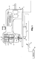
- the preferred embodiment is described as an electronic sewing machine 10 comprised of a base plate 11, a first central processing unit 20 mounted on a frame 30 and programmed to send a multiplicity of sets of instructions to the machine's parts, the CPU being equipped with memory to hold programming and data (not shown), a clock 21, a counter 22, a display 23 typically displaying up to eighty characters and a keyboard 24 or pad, the frame 30 being of cantilevered shape mounted to the base plate for holding within the frame in vertical axial alignment, a first or "up” solenoid 31 and a second or “down” solenoid 32.
- the solenoids may be annularly wire wound in coils 33 around hollow cores 34 which define a passage 35 in which a needle bar assembly 40 can reciprocate up and down and to provide fields of magnetic flux of sufficient strength to cause an iron alloy bar-shaped reciprocator 41 attached to the needle bar assembly to reciprocate between the solenoids when they are activated alternately by a first set of instructions from the first CPU.
- the needle bar assembly 40 that is the reciprocator, a needle bar 42 and a needle 43, is appropriately guided axially vertically through a defined length 44 of travel path having an up terminus 44a and a down terminus 44b by journal means 36 and a stopping plate 37, typically made of a noise-reducing material such as polyurethane.
- An external source of thread 13 is provided to feed thread under tension by means (not shown) well-known in the art.
- a bobbin assembly 50 which is cooperatively attached to a pulse driven stepper motor 51 with a shaft 52 for driving rotationally the bobbin assembly which is equipped with a supply of thread (not shown) through a defined arc of rotation.
- a treadle 60 is attached to a potentioneter circuit 61 to regulate by foot pressure the number of reciprocations per minute of the needle bar assembly, i.e. the stitch rate.
- the bobbin assembly 50 is comprised of a rotatable bobbin case 53 which is attached rotatably to the stepper motor shaft 52 for rotation, a bobbin spool (not shown) with a supply of bobbin thread disposed inside the case, and a hook 54 having a point 55, the hook cooperating with the bobbin thread to take a loop 45 formed by the needle's reciprocation to make, for example, a lock stitch.
- the first CPU is connectable to a second or host CPU 70 [(not shown)] by cables 71 for receiving and sending information or may run independently. Additionally, the first CPU is equipped with means (not shown) for sensing at each operating part the pertinent mode or position of the part at any given instant and for transmitting such mode or position to the second CPU.
- the first CPU After sending the first set of instructions to the solenoids to activate them as described below sends a second set of instructions to the stepper motor which adjustably rotates the bobbin case to the first reference or default position a defined number of degrees of rotation.
- a third set of instructions will rotate the bobbin case a defined arc of rotation clockwise from the first reference position to the second reference position.
- a fourth set of instructions will rotate the bobbin case a defined arc of rotation counter-clockwise to the third reference position. It has been estimated that the arc of rotation typically should be from zero to 20 degrees on either side of the first reference point, for example 2 degrees.
- a fifth set of instructions will rotate the bobbin case through a cycle of one revolution from its first, second or third reference point accordingly, to form a stitch.
- the first set of instructions is sent by means of the first CPU cooperatively with the potentiomenric circuit 61 to the solenoids activating their magnetic fields alternately to cause reciprocation at a speed increasingly responsive to increased treadle pressure.
- the needle bar assembly is caused thereby to descend the defined travel length 44 to the down terminus 44b, the needle with its thread thereby piercing the pieces to be sewn together.
- the needle then slightly rises from the down position to a point 44c on the travel path to from the loop 45.
- the starting time of the bobbin assembly's 360 degrees rotation for loop taking relative to the needle position is readily calculated by the CPU by means of a sixth set of instructions since the length of the reciprocation of the needle bar assembly is known as is the time of its arrival at the down terminus from the speed of reciprocations. Therefore, the loop 45 formed by the reciprocation will be of a constant diameter if the bobbin assembly commences its loop taking at the calculated starting time which coincides with the needle bar assembly passing the travel point going upward.
- a seventh set of instructions from the first CPU will cause the machine to make a run of stitches containing a defined number of stitches.
- An eighth set of instructions from the first CPU will cause the machine to make a defined number of runs.
- the first CPU by means of a ninth set of instructions can cause a halt to permit the operator to shift stitch run direction or by means of a tenth set of instructions halt the needle bar assembly at the up terminus 44a thereby allowing an operator to complete the sewing.
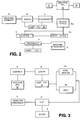
- An operator connects (A) the first CPU 20 to the host CPU 70 by turning it on and forwarding a machine I.D. to the host. Thereupon, the operator logs on (B) by the key pad 24 with a valid operator I.D. job number.
- the host CPU 70 responds by forwarding to the first CPU's memory instructions for storage therein which are responsive to the job number, the instructions comprising the second through tenth set, i.e. the number of stitch runs, the number of stitches per run, the needle position up or down at the end of each run and the tightness of stitch, from the sixth set of instructions the time to enter the loop and the bobbin case's arc of rotation relative to the first reference position if there is no default.
- the host CPU is disconnected (C) and the operator is enabled to operate the machine (Do).
- the display 23 is enabled by the counter 22 to show the number of stitches left in a run.
- the treadle 60 being connected to the potentiometric circuit 61, enables the speed of reciprocation to vary by foot pressure.
- the stitch rate can be made by additional sets of instructions to attach a preprogrammed maximum and decelerate automatically as the end of a run is reached even if the operator maintains full foot pressure.
- the counter causes the display to decrement one number per stitch. In the event of an interruption, the operator is advised accordingly of the exact point in a job where such interruption took place, thereby enabling the job to be resumed exactly where it was stopped.
- the machine is directed to reconnect (F) to the host to report job completion, operating time from the clock, machine time if different from operating time, and the like for accounting and maintenance purposes.
- a supervisor with a new design or to edit an old one, can sit at the machine and connect the first CPU to the host CPU (A).
- the supervisor at log on (B) will inform the host that either new (Cn) or edited (Ce) instructions shall be forthcoming. It is customary initially for the supervisor at log on to provide a password to the host for security purposes.
- the supervisor then actually performs sewing runs and stitches per run with the desired stitch tightness which are sensed by the mode and position sensing means as information for translation into the sets of instructions which are stored in the first CPU's memory and tested (D) in the disconnect mode. If the operation is as desired, the new or edited instructions are transmitted and stored (E) as a set of job instructions in host memory and the machine is disconnected (F).
- the supervisor at any time during a job run can halt sewing operations and edit a particular design either permanently or temporarily if job conditions, i.e. fabric variation, warrant it.
- any number of machines of the invention can retrieve from host memory instructions for any design without interfering with the operation of any other machine in connection with the host.
Landscapes
- Engineering & Computer Science (AREA)
- Textile Engineering (AREA)
- Physics & Mathematics (AREA)
- Electromagnetism (AREA)
- Mechanical Engineering (AREA)
- Sewing Machines And Sewing (AREA)
Priority Applications (4)
| Application Number | Priority Date | Filing Date | Title |
|---|---|---|---|
| US07/605,030 US5189971A (en) | 1990-10-29 | 1990-10-29 | Electronic sewing machine |
| CA002090259A CA2090259A1 (en) | 1990-10-29 | 1993-02-24 | Electronic sewing machine |
| EP93301390A EP0612877A1 (de) | 1990-10-29 | 1993-02-24 | Elektronische Nähmaschine |
| JP5039899A JPH06254280A (ja) | 1990-10-29 | 1993-03-01 | 電子ミシンおよびそれに使用するボビン |
Applications Claiming Priority (4)
| Application Number | Priority Date | Filing Date | Title |
|---|---|---|---|
| US07/605,030 US5189971A (en) | 1990-10-29 | 1990-10-29 | Electronic sewing machine |
| CA002090259A CA2090259A1 (en) | 1990-10-29 | 1993-02-24 | Electronic sewing machine |
| EP93301390A EP0612877A1 (de) | 1990-10-29 | 1993-02-24 | Elektronische Nähmaschine |
| JP5039899A JPH06254280A (ja) | 1990-10-29 | 1993-03-01 | 電子ミシンおよびそれに使用するボビン |
Publications (1)
| Publication Number | Publication Date |
|---|---|
| EP0612877A1 true EP0612877A1 (de) | 1994-08-31 |
Family
ID=27427014
Family Applications (1)
| Application Number | Title | Priority Date | Filing Date |
|---|---|---|---|
| EP93301390A Withdrawn EP0612877A1 (de) | 1990-10-29 | 1993-02-24 | Elektronische Nähmaschine |
Country Status (4)
| Country | Link |
|---|---|
| US (1) | US5189971A (de) |
| EP (1) | EP0612877A1 (de) |
| JP (1) | JPH06254280A (de) |
| CA (1) | CA2090259A1 (de) |
Cited By (4)
| Publication number | Priority date | Publication date | Assignee | Title |
|---|---|---|---|---|
| EP0759485A3 (de) * | 1995-08-11 | 1998-12-30 | Kabushiki Kaisha Toyoda Jidoshokki Seisakusho | Verschleissteilverwaltungsverfahren und -system für Textilmaschinen |
| DE19827846A1 (de) * | 1998-06-23 | 1999-12-30 | Frankl & Kirchner | Antrieb für eine Nähmaschine, insbesondere eine Industrienähmaschine |
| DE19714520C2 (de) * | 1996-04-08 | 2002-07-04 | Brother Ind Ltd | Nähmaschine |
| DE19709754B4 (de) * | 1996-03-11 | 2004-01-15 | Brother Kogyo K.K., Nagoya | Nähmaschine |
Families Citing this family (18)
| Publication number | Priority date | Publication date | Assignee | Title |
|---|---|---|---|---|
| US5189971A (en) * | 1990-10-29 | 1993-03-02 | Frankel Samuel R | Electronic sewing machine |
| JPH05137862A (ja) * | 1991-11-18 | 1993-06-01 | Tokai Ind Sewing Mach Co Ltd | ミシンの天秤駆動装置 |
| US5458075A (en) * | 1994-09-15 | 1995-10-17 | Tice Engineering And Sales, Inc. | Electronically geared sewing machine |
| US5839382A (en) * | 1994-09-15 | 1998-11-24 | Tice Engineering And Sales, Inc. | Electronically geared sewing machine |
| JPH08215468A (ja) * | 1995-02-09 | 1996-08-27 | Brother Ind Ltd | ミシン |
| EP0857228B1 (de) | 1995-10-24 | 2000-12-20 | Jimtex Developments Limited | Hin-und herbewegung der nadel |
| JP3156574B2 (ja) * | 1995-11-20 | 2001-04-16 | ブラザー工業株式会社 | ミシン |
| JPH09140971A (ja) * | 1995-11-20 | 1997-06-03 | Brother Ind Ltd | ミシン |
| JPH09140972A (ja) * | 1995-11-20 | 1997-06-03 | Brother Ind Ltd | ミシン |
| US5832851A (en) * | 1996-03-11 | 1998-11-10 | Brother Kogyo Kabushiki Kaisha | Sewing machine |
| JP3449588B2 (ja) * | 1996-03-11 | 2003-09-22 | ブラザー工業株式会社 | ミシン |
| KR100277364B1 (ko) * | 1998-06-08 | 2001-02-01 | 윤세용 | 미싱불량 자동검출 방법 및 그 장치 |
| US6135040A (en) * | 1998-09-09 | 2000-10-24 | Tice Engineering And Sales, Inc. | Felling machine |
| JP4397505B2 (ja) * | 1999-05-06 | 2010-01-13 | Juki株式会社 | ミシン |
| DE102005029876B4 (de) * | 2005-06-27 | 2009-03-19 | Kastriot Merlaku | Nähmaschine oder Antrieb-System für Nähmaschinen |
| DE102006045229A1 (de) * | 2006-09-26 | 2008-04-03 | Schaeffler Kg | Stickkopf |
| US7597058B2 (en) * | 2007-03-22 | 2009-10-06 | Aisin Seiki Kabushiki Kaisha | Apparatus for adjusting timing of needle and looptaker of sewing machine |
| JP6730000B2 (ja) * | 2015-02-25 | 2020-07-29 | 株式会社Tism | ミシン及びプログラム |
Citations (5)
| Publication number | Priority date | Publication date | Assignee | Title |
|---|---|---|---|---|
| US3425376A (en) * | 1963-07-01 | 1969-02-04 | Husqvarna Vapenfabriks Ab | Electric driving means for sewing machines |
| US3875489A (en) * | 1971-02-10 | 1975-04-01 | Brimer Joe W Von | Linear self synchronous electromagnetic drive system for a sewing machine |
| US4346334A (en) * | 1980-07-23 | 1982-08-24 | Brother Kogyo Kabushiki Kaisha | DC Servomotor system |
| US5088429A (en) * | 1990-02-13 | 1992-02-18 | Brother Kogyo Kabushiki Kaisha | Sewing machine individually driving needle bar and looper |
| US5189971A (en) * | 1990-10-29 | 1993-03-02 | Frankel Samuel R | Electronic sewing machine |
Family Cites Families (2)
| Publication number | Priority date | Publication date | Assignee | Title |
|---|---|---|---|---|
| US4241680A (en) * | 1977-03-31 | 1980-12-30 | Newroyd Limited | Device for stopping a needle at a predetermined position |
| JPH01167139A (ja) * | 1987-12-23 | 1989-06-30 | Brother Ind Ltd | 光学センサーの制御装置 |
-
1990
- 1990-10-29 US US07/605,030 patent/US5189971A/en not_active Expired - Lifetime
-
1993
- 1993-02-24 CA CA002090259A patent/CA2090259A1/en not_active Abandoned
- 1993-02-24 EP EP93301390A patent/EP0612877A1/de not_active Withdrawn
- 1993-03-01 JP JP5039899A patent/JPH06254280A/ja active Pending
Patent Citations (5)
| Publication number | Priority date | Publication date | Assignee | Title |
|---|---|---|---|---|
| US3425376A (en) * | 1963-07-01 | 1969-02-04 | Husqvarna Vapenfabriks Ab | Electric driving means for sewing machines |
| US3875489A (en) * | 1971-02-10 | 1975-04-01 | Brimer Joe W Von | Linear self synchronous electromagnetic drive system for a sewing machine |
| US4346334A (en) * | 1980-07-23 | 1982-08-24 | Brother Kogyo Kabushiki Kaisha | DC Servomotor system |
| US5088429A (en) * | 1990-02-13 | 1992-02-18 | Brother Kogyo Kabushiki Kaisha | Sewing machine individually driving needle bar and looper |
| US5189971A (en) * | 1990-10-29 | 1993-03-02 | Frankel Samuel R | Electronic sewing machine |
Non-Patent Citations (1)
| Title |
|---|
| EUREKA (INC. ENGINEERING MATERIALS AND DESIGN) vol. 13, no. 1, January 1993, KENT GB page 17 HORTON KIRBY 'sewing machine technology gets smart' * |
Cited By (6)
| Publication number | Priority date | Publication date | Assignee | Title |
|---|---|---|---|---|
| EP0759485A3 (de) * | 1995-08-11 | 1998-12-30 | Kabushiki Kaisha Toyoda Jidoshokki Seisakusho | Verschleissteilverwaltungsverfahren und -system für Textilmaschinen |
| DE19709754B4 (de) * | 1996-03-11 | 2004-01-15 | Brother Kogyo K.K., Nagoya | Nähmaschine |
| DE19714520C2 (de) * | 1996-04-08 | 2002-07-04 | Brother Ind Ltd | Nähmaschine |
| DE19827846A1 (de) * | 1998-06-23 | 1999-12-30 | Frankl & Kirchner | Antrieb für eine Nähmaschine, insbesondere eine Industrienähmaschine |
| EP0967316A3 (de) * | 1998-06-23 | 2000-07-19 | Frankl & Kirchner GmbH. & Co. KG Fabrik für Elektromotoren und elektrische Apparate | Antrieb für eine Nähmaschine, insbesondere eine Industrienähmaschine |
| DE19827846C2 (de) * | 1998-06-23 | 2001-05-31 | Frankl & Kirchner | Antrieb für eine Nähmaschine, insbesondere eine Industrienähmaschine |
Also Published As
| Publication number | Publication date |
|---|---|
| JPH06254280A (ja) | 1994-09-13 |
| US5189971A (en) | 1993-03-02 |
| CA2090259A1 (en) | 1994-08-25 |
Similar Documents
| Publication | Publication Date | Title |
|---|---|---|
| EP0612877A1 (de) | Elektronische Nähmaschine | |
| US4173192A (en) | Electrohydraulic needle bar positioning apparatus for tufting machines | |
| EP0487751B1 (de) | Stickmaschine | |
| US4682554A (en) | Method and apparatus for performing sewing operations utilizing sewing machine having means to adjust terminal stitch pitch and sew consecutive patterns | |
| US4501207A (en) | Hole sewing machine | |
| US3012530A (en) | Lock stitch sewing machines | |
| US5040476A (en) | Switching device for normal and embroidery stitching in a sewing machine | |
| DE10063002B4 (de) | Knopfloch-Overlock-Nähmaschine | |
| US3847100A (en) | Pattern selection system for sewing machines | |
| JP2700557B2 (ja) | 自動糸調子ミシン | |
| US4686918A (en) | Method and apparatus for making tufted buffing pads of varied density | |
| US5078068A (en) | Process and apparatus for preparing a seam | |
| EP0189682B1 (de) | Fadenzuführvorrichtung für Nähmaschine | |
| US2864327A (en) | Sewing machine | |
| US5146862A (en) | Sewing machine-driving apparatus | |
| JP3038576B2 (ja) | フック・アイ金具縫い付けミシン | |
| US3425376A (en) | Electric driving means for sewing machines | |
| KR100586643B1 (ko) | 재봉 또는 자수 기계 | |
| JP3016954B2 (ja) | 飾り付けミシン | |
| US4926769A (en) | Automatic sewing device with a sewing head including a rotary housing | |
| US4693193A (en) | Device of guiding drawing-out of a lower thread from a horizontal bobbin carrier of a sewing machine | |
| US4241680A (en) | Device for stopping a needle at a predetermined position | |
| US5035193A (en) | Continuous hem stitching sewing machine | |
| JPS6060895A (ja) | ボビンに下糸を巻取る方法 | |
| EP0158708B1 (de) | Fadenriss- oder Fadenenddetektor für Nähmaschine |
Legal Events
| Date | Code | Title | Description |
|---|---|---|---|
| PUAI | Public reference made under article 153(3) epc to a published international application that has entered the european phase |
Free format text: ORIGINAL CODE: 0009012 |
|
| AK | Designated contracting states |
Kind code of ref document: A1 Designated state(s): AT BE CH DE DK ES FR GB GR IE IT LI LU MC NL PT SE |
|
| 17P | Request for examination filed |
Effective date: 19950228 |
|
| 17Q | First examination report despatched |
Effective date: 19950803 |
|
| GRAG | Despatch of communication of intention to grant |
Free format text: ORIGINAL CODE: EPIDOS AGRA |
|
| GRAH | Despatch of communication of intention to grant a patent |
Free format text: ORIGINAL CODE: EPIDOS IGRA |
|
| STAA | Information on the status of an ep patent application or granted ep patent |
Free format text: STATUS: THE APPLICATION IS DEEMED TO BE WITHDRAWN |
|
| 18D | Application deemed to be withdrawn |
Effective date: 19961202 |