EP0613022A2 - Radar météorologique aérotransporté avec gain variable dans le temps (STC) en fonction de la hauteur de l'avion et de l'angle d'inclinaison de l'antenne - Google Patents
Radar météorologique aérotransporté avec gain variable dans le temps (STC) en fonction de la hauteur de l'avion et de l'angle d'inclinaison de l'antenne Download PDFInfo
- Publication number
- EP0613022A2 EP0613022A2 EP94101708A EP94101708A EP0613022A2 EP 0613022 A2 EP0613022 A2 EP 0613022A2 EP 94101708 A EP94101708 A EP 94101708A EP 94101708 A EP94101708 A EP 94101708A EP 0613022 A2 EP0613022 A2 EP 0613022A2
- Authority
- EP
- European Patent Office
- Prior art keywords
- signal
- stc
- providing
- output
- tilt angle
- Prior art date
- Legal status (The legal status is an assumption and is not a legal conclusion. Google has not performed a legal analysis and makes no representation as to the accuracy of the status listed.)
- Granted
Links
Images


Classifications
-
- G—PHYSICS
- G01—MEASURING; TESTING
- G01S—RADIO DIRECTION-FINDING; RADIO NAVIGATION; DETERMINING DISTANCE OR VELOCITY BY USE OF RADIO WAVES; LOCATING OR PRESENCE-DETECTING BY USE OF THE REFLECTION OR RERADIATION OF RADIO WAVES; ANALOGOUS ARRANGEMENTS USING OTHER WAVES
- G01S13/00—Systems using the reflection or reradiation of radio waves, e.g. radar systems; Analogous systems using reflection or reradiation of waves whose nature or wavelength is irrelevant or unspecified
- G01S13/88—Radar or analogous systems specially adapted for specific applications
- G01S13/95—Radar or analogous systems specially adapted for specific applications for meteorological use
- G01S13/953—Radar or analogous systems specially adapted for specific applications for meteorological use mounted on aircraft
-
- G—PHYSICS
- G01—MEASURING; TESTING
- G01S—RADIO DIRECTION-FINDING; RADIO NAVIGATION; DETERMINING DISTANCE OR VELOCITY BY USE OF RADIO WAVES; LOCATING OR PRESENCE-DETECTING BY USE OF THE REFLECTION OR RERADIATION OF RADIO WAVES; ANALOGOUS ARRANGEMENTS USING OTHER WAVES
- G01S7/00—Details of systems according to groups G01S13/00, G01S15/00, G01S17/00
- G01S7/02—Details of systems according to groups G01S13/00, G01S15/00, G01S17/00 of systems according to group G01S13/00
- G01S7/28—Details of pulse systems
- G01S7/285—Receivers
- G01S7/34—Gain of receiver varied automatically during pulse-recurrence period, e.g. anti-clutter gain control
-
- Y—GENERAL TAGGING OF NEW TECHNOLOGICAL DEVELOPMENTS; GENERAL TAGGING OF CROSS-SECTIONAL TECHNOLOGIES SPANNING OVER SEVERAL SECTIONS OF THE IPC; TECHNICAL SUBJECTS COVERED BY FORMER USPC CROSS-REFERENCE ART COLLECTIONS [XRACs] AND DIGESTS
- Y02—TECHNOLOGIES OR APPLICATIONS FOR MITIGATION OR ADAPTATION AGAINST CLIMATE CHANGE
- Y02A—TECHNOLOGIES FOR ADAPTATION TO CLIMATE CHANGE
- Y02A90/00—Technologies having an indirect contribution to adaptation to climate change
- Y02A90/10—Information and communication technologies [ICT] supporting adaptation to climate change, e.g. for weather forecasting or climate simulation
Definitions
- This invention relates generally to airborne weather radar systems and, more particularly, to systems of the type described with aircraft altitude and antenna tilt angle dependent sensitivity time control for normalizing return signals from a target at high as well as low altitudes.
- Sensitivity time control is a well known means for controlling the radar system receiver gain as a function of time, which is equivalent to range, in order to normalize the level of return signals from targets at different ranges.
- Weather cells i.e. thunderstorms and the like, have high reflectivity at low altitudes due to rain droplets in the weather cells resulting in high return signal levels. At higher altitudes, the water content in the weather cells is in the form of ice with much lower reflectivity resulting in low return signal levels.
- the crossover altitude between high and low reflectivity has been found to be within twenty and twenty-five thousand feet. When an aircraft is flying above these altitudes, the radar beam reacts to both low and high reflectivity of the weather cells. As a result, the return signal levels do not follow the aforementioned nominal six dB per octave slope.
- This invention relates to an airborne weather radar system with aircraft altitude and antenna tilt angle dependent sensitivity time control (STC) wherein, in one form of the invention, variable gain is used in the radar system receiver chain.
- An STC generator provides an output which is applied to the system receiver as a variable gain input.
- a trigger signal triggers radar transmission.
- the STC generator is responsive to aircraft altitude signals, antenna tilt angle signals and the trigger signal to generate the variable gain input as a function of time from transmission, aircraft altitude and antenna tilt angle.
- a fixed gain is used in the receiver chain.
- the STC generator provides an output which changes the threshold of a comparator.
- the comparator determines if a signal from the system receiver exceeds a predetermined level, in which event the signal is displayed.
- the STC generator provides the threshold signal as a function of time to transmission, aircraft altitude and antenna tilt angle, as is the case in the first mentioned form of the invention.
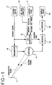
- Figure 1 is a block diagram illustrating one form of the invention.
- FIG. 2 is a block diagram illustrating another form of the invention.
- FIG. 3 is a block diagram illustrating an STC generator in accordance with the invention.
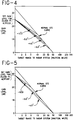
- Figure 4 is a graphical representation illustrating a set of STC curves for an aircraft altitude of thirty thousand feet and for various antenna tilt angle settings, and indicating a set return signal gain level for 30,000 feet.
- Figure 5 is a graphical representation illustrating a set of STC curves for an aircraft altitude of twenty-five thousand feet and for various antenna tilt angle settings, and indicating a set return signal gain level for twenty-five thousand feet.
- Figure 6 is a graphical representation illustrating a representative plot of set gain levels as a function of aircraft altitude.
- a control device 11 which may be a microprocessor, applies a trigger signal to a radar system transmitter 10 to initiate radar transmission.
- Transmitter 10 applies a signal to a radar system antenna 12 which transmits a radar signal.
- the signal is intercepted by a target (weather cell) 11.
- Antenna 12 receives a return signal from target 11 and thereupon applies a signal to a radar system receiver 14.
- the trigger signal from control device 11 is applied to a sensitivity time control (STC) generator 16.
- STC sensitivity time control
- Radar system antenna tilt angle signals as are available from instrumentation in a control panel 17 and aircraft altitude signals as are available from a barometer or an air data computer 19 are applied to STC generator 16.
- the STC generator provides a variable gain signal which is applied to receiver 14 for adjusting the gain of the signal applied thereto from antenna 12.
- Receiver 14 provides a gain adjusted signal which is detected by a detector 18.
- Detector 18 is of the type which is responsive to the signal from receiver 14 for providing a video signal.
- the video signal is displayed by a display means 20 so as to be observed by an observer for controlling an aircraft accordingly.
- variable gain is provided in the radar system receiver chain.
- STC is generated by STC generator 16 which varies the gain of the signal from antenna 12 applied to receiver 14.
- the variable gain is provided as a function of time for transmission, aircraft altitude and antenna tilt angle as will now be appreciated.
- STC generator 16 A preferred configuration for STC generator 16 is illustrated in Figure 3 and will be hereinafter described.
- Transmitter 10, antenna 12, receiver 14, detector 18 and display means 20 are of the type well known to those skilled in the art.
- transmitter 10 is triggered by the trigger signal from control device 11 to initiate radar transmission.
- Transmitter 10 applies a signal to antenna 12 which transmits a radar signal to target 11.
- Antenna 12 receives a return signal from target 11 and applies a signal to receiver 14 which, in turn, applies a signal to detector 18, whereupon the detector provides a video signal which is applied to detector 18, as aforenoted.
- STC generator 16 is triggered by the trigger signal from control device 11 and provides a signal in response to the aircraft altitude and antenna tilt angle signals from air data computer 19 and the instrumentation in control panel 17, respectively, and which signal is in effect a threshold signal.
- the threshold signal is applied to a comparator 22.
- the video signal from detector 18 is likewise applied to comparator 22 which determines if the video signal from detector 18 exceeds the level of the threshold signal. If the threshold signal level is exceeded, comparator 22 applies a video signal to display means 20 for observation by an observer for controlling an aircraft accordingly.
- receiver 14 has a fixed gain.
- the STC function is achieved by changing the threshold applied to comparator 22 which determines if the detected video signal from detector 18 exceeds a predetermined level to be displayed.
- the threshold signal is likewise provided as a function of time from transmission, aircraft altitude and antenna tilt angle.
- STC generator 16 is illustrated in Figure 3 as aforenoted, and will be next described.
- Comparator 22 is of the type well known to those skilled in the art.
- STC generator 16 generates a signal as a function of time, which is equivalent to the range of the airborne antenna system to a target, with reference to a transmitted radar signal.
- STC generator 16 was implemented using resistors and capacitors to generate a time dependent signal for controlling receiver gain.
- Later generation airborne radar systems used digital signal generation including digital circuitry and memory devices to store STC information and to generate a time dependent signal for controlling receiver gain through digital-to-analog converters.
- the STC generating means generally shown in Figures 1 and 2 uses digital means to generate time dependent signals for either controlling the gain of receiver 14, as shown in Figure 1, or for providing a threshold signal, as shown in Figure 2.
- Figure 3 shows the structural arrangement of STC generator 16 in accordance with a preferred embodiment of the invention.
- STC generator 16 is controlled by control device 11 and includes a random access memory (RAM) 24, a counter 26, a digital-to-analog converter 28 and a clock 29.
- Aircraft altitude and antenna tilt angle signals are applied to control device (microprocessor) 11 via air data computer 19 and control panel 17, respectively. In most aircraft, these signals arc provided to the airborne radar system via digital data buses.
- the most commonly used digital data buses for the purpose described are ARINC 429 (Aeronautical Radio, Inc.) for commercial aircraft, and MIL-STD-1553 for military aircraft. Details of these data buses are well known to those skilled in the art and are not otherwise illustrated or described.
- control device 11 determines the range at which a transmitted radar signal crosses an aircraft altitude of twenty thousand feet. Then, a set gain level is determined by the control device, based on the aircraft altitude, as illustrated by the graphical representation of Figure 6. Using the data so obtained, control device 11 determines the desired STC as a function of range. Examples of typical STC curves as a function of range are illustrated by the graphical representations of Figures 4 and 5.
- Control device 11 converts the range dependent STC data to time dependent data, based on the speed at which transmitted radar signals travel to a target and return therefrom. 12.36 microseconds per nautical mile is used for this time in most implementations.
- Control device 11 quantizes the time dependent STC data into time intervals corresponding to the period of clock 29.
- the output of the clock is applied to counter 26 as is the trigger signal from control device 11.
- STC data for each time interval with respect to the transmitted signal is stored in RAM 24 which receives a read address from counter 26.
- the data storage usually takes place during the interval between all signal returns from the previously transmitted signal, while processing occurs during the next transmission of a signal.
- Control device 11 provides a write address and input data to RAM 24.
- Counter 26 generates the addresses to read the STC data from the RAM synchronously with the trigger signal. Counter 26 is re-set to zero when the trigger signal is transmitted and advances with system clock 29.
- the data read from RAM 24 represents time dependent STC data in digital data form.
- Digital-to-analog (D/A) converter 28 converts the digital data to a time dependent analog voltage to either control the gain of receiver 14, as shown in Figure 1 or to function as a comparator threshold, as shown in Figure 2.
- the gain and threshold signals have the same wave form, although scale factors may have to be applied to the signals as will be understood by those skilled in the art, and as such is not further explained herein.
- the arrangement is such that sensitivity time control (STC) is generated with variable gain characteristics.
- STC sensitivity time control
- the gain characteristics are determined from aircraft altitude and antenna tilt angle selections. For aircraft altitudes at or below 20,000 feet, the standard STC slope of 6 dB per octave is maintained. For aircraft altitudes above 20,000 feet, 6 dB per octave slope is maintained for ranges where the radar beam center is below an altitude of 20,000 feet. Inside that range, the STC slope is altered to obtain a set gain at a range of one nautical mile. This set gain level is a function of aircraft altitude.
- the STC slope is determined on the basis of starting gain adjustment as the normal STC, but obtaining the set gain level at a range of one nautical mile based on aircraft altitude.
- the arrangement is implemented as particularly shown in Figures 1 and 2.
- STC sensitivity time control
Landscapes
- Engineering & Computer Science (AREA)
- Radar, Positioning & Navigation (AREA)
- Remote Sensing (AREA)
- Physics & Mathematics (AREA)
- Computer Networks & Wireless Communication (AREA)
- General Physics & Mathematics (AREA)
- Aviation & Aerospace Engineering (AREA)
- Electromagnetism (AREA)
- Radar Systems Or Details Thereof (AREA)
Applications Claiming Priority (2)
| Application Number | Priority Date | Filing Date | Title |
|---|---|---|---|
| US23516 | 1979-03-23 | ||
| US08/023,516 US5311184A (en) | 1993-02-26 | 1993-02-26 | Airborne weather radar system with aircraft altitude and antenna tilt angle dependent sensitivity time control |
Publications (3)
| Publication Number | Publication Date |
|---|---|
| EP0613022A2 true EP0613022A2 (fr) | 1994-08-31 |
| EP0613022A3 EP0613022A3 (fr) | 1994-11-30 |
| EP0613022B1 EP0613022B1 (fr) | 1998-09-02 |
Family
ID=21815572
Family Applications (1)
| Application Number | Title | Priority Date | Filing Date |
|---|---|---|---|
| EP94101708A Expired - Lifetime EP0613022B1 (fr) | 1993-02-26 | 1994-02-04 | Radar météorologique aérotransporté avec gain variable dans le temps (STC) en fonction de la hauteur de l'avion et de l'angle d'inclinaison de l'antenne |
Country Status (3)
| Country | Link |
|---|---|
| US (1) | US5311184A (fr) |
| EP (1) | EP0613022B1 (fr) |
| DE (1) | DE69412881T2 (fr) |
Cited By (1)
| Publication number | Priority date | Publication date | Assignee | Title |
|---|---|---|---|---|
| CN109270536A (zh) * | 2018-10-31 | 2019-01-25 | 安徽四创电子股份有限公司 | 一种多普勒天气雷达的信号处理器 |
Families Citing this family (35)
| Publication number | Priority date | Publication date | Assignee | Title |
|---|---|---|---|---|
| US5392048A (en) * | 1993-07-12 | 1995-02-21 | Alliedsignal Inc. | Weather radar system including an automatic step scan mode |
| FR2730567B1 (fr) * | 1995-02-14 | 1997-03-14 | Thomson Csf | Ensemble interrogateur pour systeme d'identification par radiodetection |
| US5615118A (en) * | 1995-12-11 | 1997-03-25 | Frank; Robert K. | Onboard aircraft flight path optimization system |
| SE511509C3 (sv) * | 1997-12-23 | 1999-11-22 | Ericsson Telefon Ab L M | Metod foer att optimera taeckningsomraadet foer en sensor |
| EP1405099B1 (fr) * | 2001-07-12 | 2017-04-19 | Honeywell International Inc. | Affichage de temps d'altitude constante et tout temps |
| US7486219B1 (en) | 2003-07-31 | 2009-02-03 | Rockwell Collins, Inc. | Adaptive weather radar detection system and method |
| US7129885B1 (en) * | 2003-07-31 | 2006-10-31 | Rockwell Collins | Adaptive weather radar detection system and method used in continental and maritime environments |
| US8203480B1 (en) | 2003-07-31 | 2012-06-19 | Rockwell Collins, Inc. | Predictive and adaptive weather radar detection system and method |
| US7515088B1 (en) * | 2003-07-31 | 2009-04-07 | Rockwell Collins, Inc. | Weather radar detection system and method that is adaptive to weather characteristics |
| US8902100B1 (en) | 2008-03-07 | 2014-12-02 | Rockwell Collins, Inc. | System and method for turbulence detection |
| JP2006064644A (ja) * | 2004-08-30 | 2006-03-09 | Tdk Corp | パルス波レーダー装置 |
| US7205928B1 (en) | 2006-05-31 | 2007-04-17 | Honeywell International Inc. | Automatic weather radar system and method |
| US7518544B2 (en) | 2006-07-13 | 2009-04-14 | Colorado State University Research Foundation | Retrieval of parameters in networked radar environments |
| US9244167B1 (en) | 2008-03-07 | 2016-01-26 | Rockwell Collins, Inc. | Long range weather information display system and method |
| US9864055B1 (en) | 2014-03-12 | 2018-01-09 | Rockwell Collins, Inc. | Weather radar system and method for detecting a high altitude crystal cloud condition |
| US9244166B1 (en) | 2008-03-07 | 2016-01-26 | Rockwell Collins, Inc. | System and method for ice detection |
| US9846230B1 (en) | 2013-03-15 | 2017-12-19 | Rockwell Collins, Inc. | System and method for ice detection |
| US9244157B1 (en) | 2008-03-07 | 2016-01-26 | Rockwell Collins, Inc. | Weather radar threat depiction system and method |
| US9057773B1 (en) | 2012-12-06 | 2015-06-16 | Rockwell Collins, Inc. | Weather information display system and method |
| JP5849245B2 (ja) | 2010-07-28 | 2016-01-27 | パナソニックIpマネジメント株式会社 | レーダ装置 |
| US9223020B1 (en) | 2010-09-28 | 2015-12-29 | Rockwell Collins, Inc. | System and method for weather detection using more than one source of radar data |
| US9213088B2 (en) * | 2011-05-17 | 2015-12-15 | Navico Holding As | Radar clutter suppression system |
| US9019146B1 (en) | 2011-09-27 | 2015-04-28 | Rockwell Collins, Inc. | Aviation display depiction of weather threats |
| US9823347B1 (en) | 2014-03-12 | 2017-11-21 | Rockwell Collins, Inc. | Weather radar system and method for high altitude crystal warning interface |
| US9116244B1 (en) | 2013-02-28 | 2015-08-25 | Rockwell Collins, Inc. | System for and method of weather phenomenon detection using multiple beams |
| US9535158B1 (en) | 2013-11-21 | 2017-01-03 | Rockwell Collins, Inc. | Weather radar system and method with fusion of multiple weather information sources |
| US9599707B1 (en) | 2014-01-23 | 2017-03-21 | Rockwell Collins, Inc. | Weather radar system and method with path attenuation shadowing |
| US9810770B1 (en) | 2014-07-03 | 2017-11-07 | Rockwell Collins, Inc. | Efficient retrieval of aviation data and weather over low bandwidth links |
| US11346979B2 (en) * | 2014-08-27 | 2022-05-31 | Dtn, Llc | Automated global weather notification system |
| US9869766B1 (en) | 2015-01-28 | 2018-01-16 | Rockwell Collins, Inc. | Enhancement of airborne weather radar performance using external weather data |
| US10809375B1 (en) | 2015-09-14 | 2020-10-20 | Rockwell Collins, Inc. | Radar system and method for detecting hazards associated with particles or bodies |
| US10302815B1 (en) | 2015-10-01 | 2019-05-28 | Rockwell Collins, Inc. | System and method of integrating global convective weather |
| US10494108B1 (en) | 2016-05-17 | 2019-12-03 | Rockwell Collins, Inc. | System and method for providing icing condition warnings |
| JP7074440B2 (ja) * | 2017-09-14 | 2022-05-24 | 日本無線株式会社 | クラッタ除去装置及びクラッタ除去プログラム |
| FR3133680B1 (fr) * | 2022-03-17 | 2024-11-01 | Thales Sa | Procede de gestion de l'altitude d'un aeronef muni d'un radar aeroporte |
Family Cites Families (6)
| Publication number | Priority date | Publication date | Assignee | Title |
|---|---|---|---|---|
| US3366951A (en) * | 1967-04-04 | 1968-01-30 | Commerce Usa | Waveform averaging and contouring device for weather radars and the like |
| US3525095A (en) * | 1968-08-06 | 1970-08-18 | Bendix Corp | Compensation for precipitation attenuation |
| US5047775A (en) * | 1990-09-27 | 1991-09-10 | Rockwell International Corporation | Automatic range adjustable weather radar system |
| JPH04190181A (ja) * | 1990-11-22 | 1992-07-08 | Komatsu Ltd | 地中埋設物探査装置のstc装置 |
| US5196854A (en) * | 1991-06-13 | 1993-03-23 | Westinghouse Electric Corp. | Inflight weather and ground mapping radar |
| US5202690A (en) * | 1992-06-02 | 1993-04-13 | Frederick Philip R | Automatic horizontal and vertical scanning radar |
-
1993
- 1993-02-26 US US08/023,516 patent/US5311184A/en not_active Expired - Lifetime
-
1994
- 1994-02-04 EP EP94101708A patent/EP0613022B1/fr not_active Expired - Lifetime
- 1994-02-04 DE DE69412881T patent/DE69412881T2/de not_active Expired - Lifetime
Cited By (2)
| Publication number | Priority date | Publication date | Assignee | Title |
|---|---|---|---|---|
| CN109270536A (zh) * | 2018-10-31 | 2019-01-25 | 安徽四创电子股份有限公司 | 一种多普勒天气雷达的信号处理器 |
| CN109270536B (zh) * | 2018-10-31 | 2020-09-01 | 安徽四创电子股份有限公司 | 一种多普勒天气雷达的信号处理器 |
Also Published As
| Publication number | Publication date |
|---|---|
| EP0613022B1 (fr) | 1998-09-02 |
| DE69412881T2 (de) | 1999-02-11 |
| DE69412881D1 (de) | 1998-10-08 |
| US5311184A (en) | 1994-05-10 |
| EP0613022A3 (fr) | 1994-11-30 |
Similar Documents
| Publication | Publication Date | Title |
|---|---|---|
| US5311184A (en) | Airborne weather radar system with aircraft altitude and antenna tilt angle dependent sensitivity time control | |
| US5164731A (en) | Turbulence radar system | |
| JP3014759B2 (ja) | マイクロバースト前兆検出システムのための下降気流速度推定装置 | |
| US7129885B1 (en) | Adaptive weather radar detection system and method used in continental and maritime environments | |
| KR100216883B1 (ko) | 마이크로파 레이다를 이용한 날씨장애 예측방법 및 장치 | |
| US7492305B1 (en) | Weather profile display system and method with uncertainty indication | |
| US7515088B1 (en) | Weather radar detection system and method that is adaptive to weather characteristics | |
| US5077558A (en) | Airborne wind shear detection weather radar | |
| US7307576B1 (en) | Hazardous and non-hazardous weather identification system and method | |
| US8203480B1 (en) | Predictive and adaptive weather radar detection system and method | |
| US7109912B1 (en) | Weather radar hazard detection system and method | |
| US4435707A (en) | Weather radar with signal compensation for precipitation | |
| US7808422B1 (en) | Predictive and adaptive weather radar detection system and method | |
| US4163216A (en) | System for transmitting airport weather information | |
| US7486219B1 (en) | Adaptive weather radar detection system and method | |
| EP0325432A2 (fr) | Système de détection de foudre à entrées multiples | |
| JPH0247711B2 (fr) | ||
| US5196854A (en) | Inflight weather and ground mapping radar | |
| US4894659A (en) | Radar altimeter systems | |
| US7777668B2 (en) | Radar altimeter with forward looking radar and data transfer capabilities | |
| CA2120236A1 (fr) | Radar de poursuite a estimation de la position de la cible | |
| US5093662A (en) | Low altitude wind shear detection with airport surveillance radars | |
| US8742973B1 (en) | System and method of determining increased turbulence susceptibility with elapsed flight time | |
| GB2103044A (en) | Weather radar simulator | |
| US4940988A (en) | Two parameter clutter map |
Legal Events
| Date | Code | Title | Description |
|---|---|---|---|
| PUAI | Public reference made under article 153(3) epc to a published international application that has entered the european phase |
Free format text: ORIGINAL CODE: 0009012 |
|
| AK | Designated contracting states |
Kind code of ref document: A2 Designated state(s): DE FR GB IT |
|
| PUAL | Search report despatched |
Free format text: ORIGINAL CODE: 0009013 |
|
| RAP1 | Party data changed (applicant data changed or rights of an application transferred) |
Owner name: ALLIEDSIGNAL INC. |
|
| AK | Designated contracting states |
Kind code of ref document: A3 Designated state(s): DE FR GB IT |
|
| 17P | Request for examination filed |
Effective date: 19950104 |
|
| 17Q | First examination report despatched |
Effective date: 19961125 |
|
| GRAG | Despatch of communication of intention to grant |
Free format text: ORIGINAL CODE: EPIDOS AGRA |
|
| GRAG | Despatch of communication of intention to grant |
Free format text: ORIGINAL CODE: EPIDOS AGRA |
|
| GRAH | Despatch of communication of intention to grant a patent |
Free format text: ORIGINAL CODE: EPIDOS IGRA |
|
| GRAH | Despatch of communication of intention to grant a patent |
Free format text: ORIGINAL CODE: EPIDOS IGRA |
|
| GRAA | (expected) grant |
Free format text: ORIGINAL CODE: 0009210 |
|
| AK | Designated contracting states |
Kind code of ref document: B1 Designated state(s): DE FR GB IT |
|
| ITF | It: translation for a ep patent filed | ||
| REF | Corresponds to: |
Ref document number: 69412881 Country of ref document: DE Date of ref document: 19981008 |
|
| ET | Fr: translation filed | ||
| PLBE | No opposition filed within time limit |
Free format text: ORIGINAL CODE: 0009261 |
|
| STAA | Information on the status of an ep patent application or granted ep patent |
Free format text: STATUS: NO OPPOSITION FILED WITHIN TIME LIMIT |
|
| 26N | No opposition filed | ||
| REG | Reference to a national code |
Ref country code: GB Ref legal event code: IF02 |
|
| PGFP | Annual fee paid to national office [announced via postgrant information from national office to epo] |
Ref country code: IT Payment date: 20100215 Year of fee payment: 17 Ref country code: FR Payment date: 20100222 Year of fee payment: 17 |
|
| PGFP | Annual fee paid to national office [announced via postgrant information from national office to epo] |
Ref country code: GB Payment date: 20100107 Year of fee payment: 17 Ref country code: DE Payment date: 20100226 Year of fee payment: 17 |
|
| GBPC | Gb: european patent ceased through non-payment of renewal fee |
Effective date: 20110204 |
|
| REG | Reference to a national code |
Ref country code: FR Ref legal event code: ST Effective date: 20111102 |
|
| PG25 | Lapsed in a contracting state [announced via postgrant information from national office to epo] |
Ref country code: IT Free format text: LAPSE BECAUSE OF NON-PAYMENT OF DUE FEES Effective date: 20110204 |
|
| REG | Reference to a national code |
Ref country code: DE Ref legal event code: R119 Ref document number: 69412881 Country of ref document: DE Effective date: 20110901 |
|
| PG25 | Lapsed in a contracting state [announced via postgrant information from national office to epo] |
Ref country code: FR Free format text: LAPSE BECAUSE OF NON-PAYMENT OF DUE FEES Effective date: 20110228 |
|
| PG25 | Lapsed in a contracting state [announced via postgrant information from national office to epo] |
Ref country code: GB Free format text: LAPSE BECAUSE OF NON-PAYMENT OF DUE FEES Effective date: 20110204 |
|
| PG25 | Lapsed in a contracting state [announced via postgrant information from national office to epo] |
Ref country code: DE Free format text: LAPSE BECAUSE OF NON-PAYMENT OF DUE FEES Effective date: 20110901 |
|
| P01 | Opt-out of the competence of the unified patent court (upc) registered |
Effective date: 20230525 |