EP0613140A2 - Appareil d'enregistrement et de reproduction d'informations - Google Patents
Appareil d'enregistrement et de reproduction d'informations Download PDFInfo
- Publication number
- EP0613140A2 EP0613140A2 EP94102744A EP94102744A EP0613140A2 EP 0613140 A2 EP0613140 A2 EP 0613140A2 EP 94102744 A EP94102744 A EP 94102744A EP 94102744 A EP94102744 A EP 94102744A EP 0613140 A2 EP0613140 A2 EP 0613140A2
- Authority
- EP
- European Patent Office
- Prior art keywords
- card
- guide rail
- auxiliary
- bearing
- carriage
- Prior art date
- Legal status (The legal status is an assumption and is not a legal conclusion. Google has not performed a legal analysis and makes no representation as to the accuracy of the status listed.)
- Granted
Links
Images



Classifications
-
- G—PHYSICS
- G06—COMPUTING OR CALCULATING; COUNTING
- G06K—GRAPHICAL DATA READING; PRESENTATION OF DATA; RECORD CARRIERS; HANDLING RECORD CARRIERS
- G06K7/00—Methods or arrangements for sensing record carriers, e.g. for reading patterns
- G06K7/10—Methods or arrangements for sensing record carriers, e.g. for reading patterns by electromagnetic radiation, e.g. optical sensing; by corpuscular radiation
- G06K7/10544—Methods or arrangements for sensing record carriers, e.g. for reading patterns by electromagnetic radiation, e.g. optical sensing; by corpuscular radiation by scanning of the records by radiation in the optical part of the electromagnetic spectrum
- G06K7/10821—Methods or arrangements for sensing record carriers, e.g. for reading patterns by electromagnetic radiation, e.g. optical sensing; by corpuscular radiation by scanning of the records by radiation in the optical part of the electromagnetic spectrum further details of bar or optical code scanning devices
- G06K7/1097—Optical sensing of electronic memory record carriers, such as interrogation of RFIDs with an additional optical interface
-
- G—PHYSICS
- G06—COMPUTING OR CALCULATING; COUNTING
- G06K—GRAPHICAL DATA READING; PRESENTATION OF DATA; RECORD CARRIERS; HANDLING RECORD CARRIERS
- G06K13/00—Conveying record carriers from one station to another, e.g. from stack to punching mechanism
- G06K13/02—Conveying record carriers from one station to another, e.g. from stack to punching mechanism the record carrier having longitudinal dimension comparable with transverse dimension, e.g. punched card
- G06K13/08—Feeding or discharging cards
-
- G—PHYSICS
- G06—COMPUTING OR CALCULATING; COUNTING
- G06K—GRAPHICAL DATA READING; PRESENTATION OF DATA; RECORD CARRIERS; HANDLING RECORD CARRIERS
- G06K13/00—Conveying record carriers from one station to another, e.g. from stack to punching mechanism
- G06K13/02—Conveying record carriers from one station to another, e.g. from stack to punching mechanism the record carrier having longitudinal dimension comparable with transverse dimension, e.g. punched card
- G06K13/08—Feeding or discharging cards
- G06K13/0806—Feeding or discharging cards using an arrangement for ejection of an inserted card
- G06K13/0831—Feeding or discharging cards using an arrangement for ejection of an inserted card the ejection arrangement comprising a slide, carriage or drawer
-
- G—PHYSICS
- G11—INFORMATION STORAGE
- G11B—INFORMATION STORAGE BASED ON RELATIVE MOVEMENT BETWEEN RECORD CARRIER AND TRANSDUCER
- G11B17/00—Guiding record carriers not specifically of filamentary or web form, or of supports therefor
- G11B17/02—Details
- G11B17/04—Feeding or guiding single record carrier to or from transducer unit
- G11B17/0408—Feeding or guiding single record carrier to or from transducer unit of non-disc record carrier, e.g. card
-
- G—PHYSICS
- G11—INFORMATION STORAGE
- G11B—INFORMATION STORAGE BASED ON RELATIVE MOVEMENT BETWEEN RECORD CARRIER AND TRANSDUCER
- G11B25/00—Apparatus characterised by the shape of record carrier employed but not specific to the method of recording or reproducing, e.g. dictating apparatus; Combinations of such apparatus
- G11B25/04—Apparatus characterised by the shape of record carrier employed but not specific to the method of recording or reproducing, e.g. dictating apparatus; Combinations of such apparatus using flat record carriers, e.g. disc, card
Definitions
- the present invention relates to an information recording and reproducing apparatus and more particularly to an information recording and reproducing apparatus in which a card carriage is guided by a pair of lying guide rails to reciprocate a predetermined stroke.
- the optical memory card is moved linearly forward and rearward relative to an optical recording and reproducing head and the optical head scans a data track on the optical memory card to write and read information into and out of the optical memory card.
- a drive means such as a linear motor moves a card carriage in a rectangular form a predetermined stroke at a high speed so that the optical memory card carriage is guided by lying parallel main and auxiliary guide rails having circular cross sections.
- the main and auxiliary rails extend along a travel direction of the optical memory card, and bearings of the card carriage having bearing bores in the round cylindrical form engage the two guide rails. Since it is difficult to obtain an accurate parallelism of the two guide rails, it is difficult to smoothly move the card carriage.
- the prior art information recording and reproducing system has the following drawback: While the main plain bearing is sufficiently durable for a longtime service since the main plain bearing has a round cylindrical bore the overall edge surface of which is in sliding contact with the main guide rail, the auxiliary plain bearing is in line contact with a certain portion of the auxiliary guide rail. Therefore, a wearing due to this line contact tends to proceed in the service of the apparatus and the auxiliary plain bearing has a poor durability. The wearing makes it difficult to maintain the level of the upper surface of the card carriage at an initial level, so that a predetermined distance for recording and reproducing data between the optical recording and reproducing head and the optical memory card can not be accurately maintained. Since the card carriage experiences an oscillation due to the wearing at a certain position in the bearing surface of the auxiliary plain bearing, the card carriage does not stably reciprocate. This adversely affects a recording and a reproduction of the information on and from the optical memory card.
- the card carriage is usually mounted within an apparatus case.
- the front portion of the apparatus case has a front panel mounted thereon and having a card receiving slot.
- the thickness of the apparatus case tends to be reduced. This entails a drawback that a reduced distance between a mounting surface to which the apparatus is mounted and the card receiving slot may contact a hand and fingers of an operator holding the optical memory card with the mounting surface. Therefore, it is difficult to insert the optical memory card into the card receiving slot.
- a primary object of the present invention is to provide an information recording and reproducing apparatus which overcomes the drawback in the prior art and which prevents a portion of an auxiliary plain bearing of a card carriage in contact with an auxiliary guide rail from being locally worn to preclude an oscillation due to the local wearing and stably move the card carriage forward and rearward for a long time.
- Another object of the present invention is to provide an information recording and reproducing apparatus having a card receiving slot into which an operator can insert an optical memory card without fretting a data storage region in the optical memory card.
- a first embodiment of the present invention comprises: a chassis; a main guide rail and an auxiliary guide rail spaced on an upper surface of said chassis, the main guide rail and the auxiliary guide rail respectively having circular cross sections; a card carriage capable of retaining an optical memory card, the card carriage being slidably mounted by means of main and auxiliary bearings on the main and auxiliary guide rails and linearly movable along the main and auxiliary guide rails; a head carriage movable perpendicularly to the direction of a movement of the card carriage; an optical recording and reproducing head, fixedly mounted on the head carriage, for recording and reproducing data into and out of the optical memory card.
- the axis of said auxiliary guide rail is positioned in the same plane as the axis of said main guide rail.
- the axis of said auxiliary guide rail is oblique at a predetermined very small angle to the axis of the main guide rail.
- the main guide bearing has a round cylindrical bearing surface fitting the cylindrical surface of the main guide rail.
- the auxiliary plain bearing has a bearing bore having a slot-shaped cross section. Opposite edge surfaces of the bearing bore of the auxiliary bearing are in contact with the cylindrical surface of the auxiliary guide rail.
- the auxiliary bearing may have a U-shaped bearing surface the opposite portions of which are in contact with the cylindrical surface of the auxiliary guide rail.
- auxiliary guide rail is oblique at a predetermined very small angle to the main guide rail, contact portions of the bearing surfaces of the auxiliary bearing are displaced transversely from the axis of the main guide rail during the stroke of the card carriage. This displacement prevents the bearing surfaces of the auxiliary bearing from being locally linearly worn to suppress an oscillation of the card carriage during the forward and rearward strokes of the card carriage and enable stable forward and rearward strokes of the card carriage.
- Another embodiment of the present invention comprises: a front panel having a card receiving slot horizontally extending; an optical memory card including a data storage region and capable of being inserted into the card receiving slot; an optical head recording and reproducing data into and out of the data storage region in the optical memory card; a card carriage retaining the optical memory card and transferring the optical memory card between the card receiving slot and the optical head; and a card receiver adjoining the lower edge of the card receiving slot, an upper surface of the card receiver being flush with the lower edge surface of the card receiving slot, the card receiver projecting forward from the front panel.
- the front panel since the front panel includes the card receiving plate in front of the card receiving slot, an operator can approaches the optical memory card from above the card receiving slot down to the card receiving slot in front of the front panel and contacts the front end of the optical memory card with the card receiving plate.
- the upper edge of the card receiving slot may have a concave surface. This arrangement protects the data storage region in the optical memory card from being fretted due to a friction between the data storage region the upper edge line of the card receiving slot.
- FIG. 1 is a perspective view of an information recording and reproducing apparatus according to a first embodiment of the present invention.
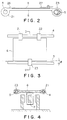
- FIG. 2 is a sectional view taken along the line A-A in FIG. 1, showing a card retention state of card retainers of the information recording and reproducing apparatus of FIG. 1.
- FIG. 3 is a plan view of a card carriage in a front stop position.
- FIG. 4 is a sectional view taken along the line D-D in FIG. 3.
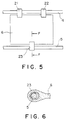
- FIG. 5 is a plan view of a card carriage in a rearmost stop position.
- FIG. 6 is a sectional view taken along the line F-F in the FIG. 5.
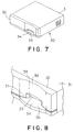
- FIG. 7 is a perspective view of an information recording and reproducing apparatus according to a second embodiment of the present invention.
- FIG. 8 is a perspective view of part of a front panel of the information recording and reproducing apparatus of FIG. 7.
- FIG. 9 is a plan view of part of the front panel of FIG. 7, showing that a optical memory card is going to be inserted into the information recording and reproducing apparatus of FIG. 7.
- FIG. 10 is a front elevation of the front panel of FIG. 7.
- FIG. 11 is an illustration of a state of inserting the optical memory card into a card receiving slot of the information recording and reproducing apparatus of FIG. 7.
- FIG. 1 is a perspective view of an information recording and reproducing apparatus according to a first embodiment of the present invention.
- a rectangular chassis is indicated at 1.
- Four corners of the chassis 1 have upright brackets 2a, 2b, 3a and 3b mounted thereon.
- a main guide rail 4 has a circular cross section and horizontally extends between the brackets 2a and 2b.
- An auxiliary guide rail 5 has a circular cross section and horizontally extends between the brackets 3a and 3b.
- the guide rails 4 and 5 are positioned so that the axes of them lie in the same horizontal plane and so that the axis of the auxiliary guide rail 5 is oblique at a predetermined very small angle ⁇ to the axis of the main guide rail 4.
- the main guide rail 4 and the auxiliary guide rail 5 are not parallel to each other and extensions thereof intersect each other at a certain point.
- a card carriage 6 in the form of a rectangular board is mounted longitudinally slidably to the main guide rail 4 and the auxiliary guide rail 5.
- a linear motor 7 moves the card carriage 6 between a front stop position and a rearmost stop position.
- An upper surface of the card carriage 6 retains a rectangular optical memory card 8 in a predetermined position.
- the optical memory card 8 includes a rectangular data storage region 9a as a central region extending along the longitudinal axis thereof and data-free or guard regions 9b adjoining the opposite longitudinal peripheries of the data storage region 9a.
- a front mask unit 10 is mounted by means of a bracket (not shown) on the upper surface of a stepped-down floor extending forward from the front end of the chassis 1.
- the front mask unit 10 has a card passage 11 extending through it along the antero-posterior axis of it.
- the front end of the card passage 11 has a card receiving slot 12.
- the rear end of the card passage 11 has a card discharging slot 13.
- the optical memory card 8 is inserted into the card receiving slot 12, let out through the card discharging slot 13 and transferred to the upper surface of the card carriage 6.
- the front mask unit 10 has a slot 14 extending along the antero-posterior axis thereof.
- a feed roller set which pinches the optical memory card 8 and delivers it to the upper surface of the card carriage 6 is mounted in the slot 14.
- the feed roller set comprises a pair of drive rollers 16 driven by an electrical motor and belt assembly (not shown), and follower rollers 17 mating the drive rollers 16.
- the drive rollers 16 and the follower rollers 17 serve as pinch rollers pinching the optical memory card 8.
- a card sensor (not shown) provided in the card receiving slot 12 senses the optical memory card 8 and produces a signal for moving the electrical motor.
- the electrical motor rotates the drive rollers 16 and in turn the feed roller set delivers the optical memory card 8 to the upper surface of the card carriage 6 through the card discharging slot 13.
- an optical recording and reproducing head 18 is supported on a head carriage frame (not shown).
- a linear motor (not shown) moves the optical head 18 up and down perpendicularly to the travel direction of the card carriage 6.
- the optical head 18 includes a laser source 19.
- the laser source 19 transmits a laser beam for writing and reading data to the data storage region 9a in the optical memory card 8.
- a main-guide-rail-side edge of the card carriage 6 has two main plain bearings 21 and 22.
- Each of the main plain bearings 21 and 22 has a round cylindrical bearing bore and is in sliding contact with the main guide rail 4.
- an auxiliary-guide-rail-side edge of the card carriage 6 has an auxiliary plain bearing 23.
- the auxiliary plain bearing 23 has a bearing bore having a generally elliptic cross section and is in contact with the auxiliary guide rail 5.
- the edge of the bearing bore of the auxiliary plain bearing 23 includes flat upper and lower surfaces in contact with the auxiliary guide rail 5.
- the card carriage 6 is movable forward and rearward along the main and auxiliary guide rails 4 and 5 so that the main plain bearings 21 and 22 are in sliding contact with the main guide rail 4 and the auxiliary plain bearing 23 is in sliding contact with the auxiliary guide rail 5.
- the main guide rail 4 has two stop bushings 24 and 25 mounted thereon.
- the front stop position of the card carriage 6 is defined as a position in which the position of the card carriage 6 is nearest to the card discharging slot 13 of the front mask unit 10 in the stroke of the card carriage 6.
- the front edge surface of the main plain bearing 21 contacts the front stop bushing 24 to delimit the forward stoke of the card carriage 6.
- the rearmost stop position of the card carriage 6 is defined as a position in which the position of the card carriage 6 is remotest from the card discharging slot 13 in the stroke of the card carriage 6.
- the rear edge surface of the main plain bearing 22 contacts the rearmost stop bushing 25 to delimit the rearward stroke of the card carriage 6.
- the main-guide-rail-side edge of the card carriage 6 has a rigid card retainer plate 26.
- the auxiliary-guide-rail-side edge of the card carriage 6 has a flexible card retainer plate 27.
- the card retainer plates 26 and 27 can retain the optical memory card 8 on the upper surface of the card carriage 6.
- contact portions of the upper and lower bearing surfaces of the auxiliary plain bearing 23 are displaced transversely from the axis of the main guide rail 4 during the stroke of the card carriage 6 between the front and rearmost stop positions.
- FIGS. 3 and 4 show the card carriage 6 in the front stop position.
- FIGS. 5 and 6 show the card carriage 6 in the rearmost stop position.
- the contact portions of the upper and lower bearing surfaces of the auxiliary plain bearing 23 are displaced transversely to the direction of the stroke of the card carriage 6.
- the lengths of the upper and lower bearing surfaces of the auxiliary plain bearing 5 must cover at least a transverse displacement of cos(90- ⁇ )° during the stroke of the card carriage 6 with the auxiliary plain guide rail 5 oblique at a very small angle ⁇ ° to the main plain guide rail 4.
- the shape of the cross section of the bearing bore of the auxiliary plain bearing 23 is not restricted to a generally ellipsis having upper and lower flat sides but may be, e.g., a U-shape having upper and lower flat sides. Since the open ends of the cross section of such U-shaped auxiliary plain bearing may gradually increase during a longtime service, the auxiliary plain bearing having a bearing bore with such elliptic cross section can ensure more stable forward and rearward strokes of the card carriage 6.
- FIGS. 7-11 show an information recording and reproducing apparatus according to a second embodiment of the present invention.
- the rectangular information recording and reproducing apparatus which is mounted on a mounting surface 30 has a reduced thickness.
- the apparatus comprises a main casing 31 in the form of a box.
- the front portion of the main casing 31 has a front panel 32 mounted thereon.
- the opposite sidewalls of the main casing 31 have ventilating openings.
- the front panel 32 has a lying card receiving slot 33.
- the operator inserts the optical memory card 8 into the apparatus through the card receiving slot 33.
- the front panel 32 has a card receiving plate 34 adjoining the lower edge of the card receiving slot 33.
- the card receiving plate 34 has a convex front edge projecting forward from the front panel 32.
- the upper surface 35, receiving and contacting the optical memory card 8, of the card receiving plate 34 is flat and flush with the bottom surface of the card receiving slot 33.
- the upper surface 35 extends forward from the lower edge of the card receiving slot 33 and is generally sector-shaped.
- the maximum length of the card receiving plate 34 is larger than the length of the card receiving slot 33.
- a portion of the front panel 32 extending upward from the upper edge of the card receiving slot 33 has a concave surface 36 in the inner cylindrical form.
- the concave surface 36 has the length equal to the maximum length of the card receiving plate 34.
- the side edges of the card receiving slot 33 have bevelled surfaces 37.
- the upper edge of the card receiving slot 33 has a bevelled surface 38.
- These bevelled surfaces 37 and 38 facilitate the operator to insert the optical memory card 8 into the card receiving slot 33. Therefore, a boundary between the concave surface 36 and the upper bevelled surface 38 forms the upper edge line of the card receiving slot 33. Since the concave surface 36 swells in a direction of the insertion of the optical memory card 8, the upper edge line of the card receiving slot 33 is convex upward.
- the upper and lower wall surfaces of the card receiving slot 33 have protrusions 39 contacting the guard regions 9b in the optical memory card 8 in order to protect the data storage region 9a in the optical memory card 8 from being fretted when the operator inserts the optical memory card 8 into the card receiving slot 33.
- the operator In operation, the operator, as shown in FIG. 11, approaches the optical memory card 8 from above the card receiving slot 33 down to the card receiving slot 33 in front of the front panel 32 on the apparatus mounted on the mounting surface 30. The operator then contacts the front end of the optical memory card 8 with the upper surface 35 of the card receiving plate 34. The operator then falls the optical memory card 8 in the direction of the arrow M and orients the optical memory card 8 along the axis of the card receiving slot 33.
- the operator can approaches the optical memory card 8 from above the card receiving slot 33 down to the card receiving slot 33 in front of the front panel 32 and contacts the front end of the optical memory card 8 with the upper surface 35 of the card receiving plate 34.
- This eliminates the need for a parallel movement of the optical memory card 8 to the mounting surface 30 for inserting it into the card receiving slot 33.
- This also prevents a hand and fingers of the operator holding the optical memory card 8 from contacting the mounting surface 30 and facilitates the operator to smoothly insert the optical memory card 8 into the card receiving slot 33.
Landscapes
- Physics & Mathematics (AREA)
- Engineering & Computer Science (AREA)
- General Physics & Mathematics (AREA)
- Theoretical Computer Science (AREA)
- Electromagnetism (AREA)
- General Health & Medical Sciences (AREA)
- Health & Medical Sciences (AREA)
- Toxicology (AREA)
- Artificial Intelligence (AREA)
- Computer Vision & Pattern Recognition (AREA)
- Optical Recording Or Reproduction (AREA)
- Moving Of Heads (AREA)
- Conveying Record Carriers (AREA)
- Credit Cards Or The Like (AREA)
Priority Applications (1)
| Application Number | Priority Date | Filing Date | Title |
|---|---|---|---|
| EP97119881A EP0831485B1 (fr) | 1993-02-26 | 1994-02-24 | Appareil d'enregistrement et de reproduction d'informations |
Applications Claiming Priority (6)
| Application Number | Priority Date | Filing Date | Title |
|---|---|---|---|
| JP5038362A JP3056607B2 (ja) | 1993-02-26 | 1993-02-26 | 情報記録再生装置 |
| JP3836293 | 1993-02-26 | ||
| JP38362/93 | 1993-02-26 | ||
| JP5134612A JP2986650B2 (ja) | 1993-06-04 | 1993-06-04 | 情報記録再生装置 |
| JP13461293 | 1993-06-04 | ||
| JP134612/93 | 1993-06-04 |
Related Child Applications (1)
| Application Number | Title | Priority Date | Filing Date |
|---|---|---|---|
| EP97119881A Division EP0831485B1 (fr) | 1993-02-26 | 1994-02-24 | Appareil d'enregistrement et de reproduction d'informations |
Publications (3)
| Publication Number | Publication Date |
|---|---|
| EP0613140A2 true EP0613140A2 (fr) | 1994-08-31 |
| EP0613140A3 EP0613140A3 (fr) | 1995-03-01 |
| EP0613140B1 EP0613140B1 (fr) | 1999-08-25 |
Family
ID=26377603
Family Applications (2)
| Application Number | Title | Priority Date | Filing Date |
|---|---|---|---|
| EP97119881A Expired - Lifetime EP0831485B1 (fr) | 1993-02-26 | 1994-02-24 | Appareil d'enregistrement et de reproduction d'informations |
| EP94102744A Expired - Lifetime EP0613140B1 (fr) | 1993-02-26 | 1994-02-24 | Appareil d'enregistrement et de reproduction d'informations |
Family Applications Before (1)
| Application Number | Title | Priority Date | Filing Date |
|---|---|---|---|
| EP97119881A Expired - Lifetime EP0831485B1 (fr) | 1993-02-26 | 1994-02-24 | Appareil d'enregistrement et de reproduction d'informations |
Country Status (8)
| Country | Link |
|---|---|
| US (2) | US5608699A (fr) |
| EP (2) | EP0831485B1 (fr) |
| KR (1) | KR100188900B1 (fr) |
| CN (1) | CN1045836C (fr) |
| AU (1) | AU665894B2 (fr) |
| CA (1) | CA2116156C (fr) |
| DE (2) | DE69430392T2 (fr) |
| TW (2) | TW257860B (fr) |
Cited By (2)
| Publication number | Priority date | Publication date | Assignee | Title |
|---|---|---|---|---|
| EP1154411A1 (fr) * | 2000-05-09 | 2001-11-14 | I-Ming Chen | Support de stockage de données et appareil de lecture d'un support de stockage de données |
| FR2855305A1 (fr) * | 2003-05-22 | 2004-11-26 | Renault Sa | Lecteur de disques comportant un moyen de guidage pour l'introduction d'un disque |
Families Citing this family (10)
| Publication number | Priority date | Publication date | Assignee | Title |
|---|---|---|---|---|
| US6938825B1 (en) | 1989-04-24 | 2005-09-06 | Ultracard, Inc. | Data system |
| US6311893B1 (en) * | 1998-04-09 | 2001-11-06 | Dcard, Inc. | Optical data access system with data card reader having a single rotational moving pickup head |
| US6871787B1 (en) | 1998-07-10 | 2005-03-29 | Ultracard, Inc. | Data storage card having a glass substrate and data surface region and method for using same |
| US8397998B1 (en) | 1999-10-23 | 2013-03-19 | Ultracard, Inc. | Data storage device, apparatus and method for using same |
| US7487908B1 (en) | 1999-10-23 | 2009-02-10 | Ultracard, Inc. | Article having an embedded accessible storage member, apparatus and method for using same |
| US7036739B1 (en) | 1999-10-23 | 2006-05-02 | Ultracard, Inc. | Data storage device apparatus and method for using same |
| US6969006B1 (en) | 2000-09-15 | 2005-11-29 | Ultracard, Inc. | Rotable portable card having a data storage device, apparatus and method for using same |
| GB2386458B (en) * | 2000-11-17 | 2004-06-16 | Sankyo Seiki Seisakusho Kk | Foreign matter detecting mechanism, carriage moving mechanism and method for operating carriage moving mechanism |
| GB2391989B (en) * | 2001-04-12 | 2004-12-01 | Sankyo Seiki Seisakusho Kk | Card forcible ejection mechanism |
| CN109742639B (zh) * | 2019-03-07 | 2023-12-08 | 深圳市迅科达智能科技有限公司 | Sim卡插拔机构 |
Family Cites Families (23)
| Publication number | Priority date | Publication date | Assignee | Title |
|---|---|---|---|---|
| DE1099201B (de) * | 1957-09-04 | 1961-02-09 | Telefunken Gmbh | Magnettondiktiergeraet mit folienfoermigem Aufzeichnungstraeger und rotierendem Auflageteller |
| DE1099101B (de) * | 1959-03-21 | 1961-02-09 | Siemens Ag | Regel- und Abschaltelement fuer Kernreaktoren |
| US3706860A (en) * | 1970-08-20 | 1972-12-19 | Wiltek Inc | Magnetic card data recorder/reproducer |
| US3766687A (en) * | 1972-02-16 | 1973-10-23 | Docutel Corp | Apparatus for entry control |
| US3959623A (en) * | 1973-03-08 | 1976-05-25 | Kabushiki Kaisha Sankyo Seiki Seisakusho | Card cassette |
| US3909595A (en) * | 1974-08-08 | 1975-09-30 | Diebold Inc | Entry gate construction for credit card actuated automatic remote banking equipment |
| US4048476A (en) * | 1976-04-09 | 1977-09-13 | Ncr Corporation | Card reader |
| US4236667A (en) * | 1979-07-20 | 1980-12-02 | Amp Incorporated | Low insertion force card reader |
| DE3034517C1 (de) * | 1980-09-12 | 1987-01-02 | Copytex-Abrechnungssysteme für Dienstleistungsautomaten GbmH, 7742 St Georgen | Vorrichtung zum Transport eines Datentraegers in einer Datenerkennungseinrichtung |
| JPS6173260A (ja) * | 1984-09-18 | 1986-04-15 | Matsushita Electric Ind Co Ltd | 磁気カ−ド記録再生装置 |
| JP2542359B2 (ja) * | 1985-05-22 | 1996-10-09 | キヤノン株式会社 | 情報記録再生装置 |
| JPS62132264A (ja) * | 1985-12-05 | 1987-06-15 | Toshiba Corp | 光学式カ−ドの搬送保持機構 |
| US4916687A (en) * | 1986-05-13 | 1990-04-10 | Canon Kabushiki Kaisha | Apparatus for mounting and rotating an optical card for recording and/or reproducing information |
| JP2754530B2 (ja) * | 1986-07-25 | 1998-05-20 | オムロン株式会社 | カード処理装置 |
| US4837814A (en) * | 1986-09-29 | 1989-06-06 | Anritsu Corporation | Telephone set |
| JPS63200291A (ja) * | 1987-02-16 | 1988-08-18 | Toshiba Corp | 媒体処理装置 |
| EP0296590B1 (fr) * | 1987-06-23 | 1993-10-27 | Omron Tateisi Electronics Co. | Appareil de traitement de carte optique |
| JPH01118275A (ja) * | 1987-10-31 | 1989-05-10 | Toshiba Corp | 光学ヘッド駆動装置 |
| AT394462B (de) * | 1990-06-01 | 1992-04-10 | Philips Nv | Abtasteinrichtung fuer eine chipkarte |
| JPH0486292U (fr) * | 1990-11-22 | 1992-07-27 | ||
| JP3311362B2 (ja) * | 1991-04-10 | 2002-08-05 | 株式会社日本コンラックス | 情報記録再生装置 |
| US5434404A (en) * | 1991-10-11 | 1995-07-18 | Verifone, Inc. | Linear scanner apparatus for communicating with a data card |
| AU5538494A (en) * | 1992-10-30 | 1994-05-24 | Microbilt Corporation | Multi-reader transaction terminal |
-
1994
- 1994-02-21 TW TW084101475A patent/TW257860B/zh active
- 1994-02-21 TW TW083101441A patent/TW251365B/zh active
- 1994-02-22 CA CA002116156A patent/CA2116156C/fr not_active Expired - Fee Related
- 1994-02-23 US US08/200,740 patent/US5608699A/en not_active Expired - Fee Related
- 1994-02-24 DE DE69430392T patent/DE69430392T2/de not_active Expired - Fee Related
- 1994-02-24 DE DE69420159T patent/DE69420159T2/de not_active Expired - Fee Related
- 1994-02-24 KR KR1019940003265A patent/KR100188900B1/ko not_active Expired - Fee Related
- 1994-02-24 AU AU56376/94A patent/AU665894B2/en not_active Ceased
- 1994-02-24 EP EP97119881A patent/EP0831485B1/fr not_active Expired - Lifetime
- 1994-02-24 EP EP94102744A patent/EP0613140B1/fr not_active Expired - Lifetime
- 1994-02-26 CN CN94104079A patent/CN1045836C/zh not_active Expired - Fee Related
-
1996
- 1996-11-06 US US08/743,706 patent/US5801368A/en not_active Expired - Fee Related
Cited By (2)
| Publication number | Priority date | Publication date | Assignee | Title |
|---|---|---|---|---|
| EP1154411A1 (fr) * | 2000-05-09 | 2001-11-14 | I-Ming Chen | Support de stockage de données et appareil de lecture d'un support de stockage de données |
| FR2855305A1 (fr) * | 2003-05-22 | 2004-11-26 | Renault Sa | Lecteur de disques comportant un moyen de guidage pour l'introduction d'un disque |
Also Published As
| Publication number | Publication date |
|---|---|
| DE69420159D1 (de) | 1999-09-30 |
| AU665894B2 (en) | 1996-01-18 |
| CA2116156A1 (fr) | 1994-08-27 |
| CN1045836C (zh) | 1999-10-20 |
| DE69420159T2 (de) | 1999-12-09 |
| DE69430392T2 (de) | 2003-01-09 |
| TW251365B (fr) | 1995-07-11 |
| US5801368A (en) | 1998-09-01 |
| US5608699A (en) | 1997-03-04 |
| CN1101743A (zh) | 1995-04-19 |
| TW257860B (fr) | 1995-09-21 |
| KR100188900B1 (ko) | 1999-06-01 |
| EP0831485B1 (fr) | 2002-04-10 |
| EP0831485A1 (fr) | 1998-03-25 |
| DE69430392D1 (de) | 2002-05-16 |
| CA2116156C (fr) | 1996-09-10 |
| EP0613140B1 (fr) | 1999-08-25 |
| EP0613140A3 (fr) | 1995-03-01 |
| AU5637694A (en) | 1994-09-15 |
Similar Documents
| Publication | Publication Date | Title |
|---|---|---|
| CA2116156C (fr) | Appareil d'enregistrement et de lecture d'informations | |
| CA2063825C (fr) | Dispositif de fixation de tete magnetique pour film photographique | |
| EP0386705B1 (fr) | Procédé de traitement de carte optique | |
| EP0767440B1 (fr) | Lecteur/enregistreur de cartes | |
| EP0836148A2 (fr) | Lecteur de carte avec une suspension du type cardan | |
| US5696369A (en) | Information recording and/or reproducing apparatus provided with mechanism for carrying medium | |
| US5104058A (en) | Tape guidance system for belt-driven cartridge | |
| US5017764A (en) | Apparatus for driving card-like record medium | |
| JP2002205436A (ja) | 走査装置 | |
| US5774306A (en) | Multi-channel, high speed, tape head contour | |
| AU692315B2 (en) | Information recording and reproducing apparatus | |
| EP0296590B1 (fr) | Appareil de traitement de carte optique | |
| NL8103564A (nl) | Inrichting voor het transporteren van een datadrager in een dataherkenningsinrichting. | |
| US4846589A (en) | Scanning carriage system useful for optical scanners | |
| EP0376688A2 (fr) | Porteur de carte | |
| US5497955A (en) | Mechanical lock-out for preventing tape cartridge insertion into incompatible drives | |
| KR910007200B1 (ko) | 카 셋 트 | |
| JPH04311870A (ja) | 情報記録再生装置 | |
| KR900702406A (ko) | 필름상에 자기적으로 기록하는 카메라 장치 | |
| JPH0567250A (ja) | 複合型カードの記録再生装置 | |
| KR100366732B1 (ko) | 헤드유지장치및매체취급장치 | |
| JPH02281464A (ja) | カードリーダライタ | |
| US6392835B1 (en) | Information recording medium library apparatus in which the position of the drive is fixed in the sub body of the apparatus | |
| JPH04344368A (ja) | 光カード駆動装置 | |
| JPS61283066A (ja) | 光学的情報記録再生装置 |
Legal Events
| Date | Code | Title | Description |
|---|---|---|---|
| PUAI | Public reference made under article 153(3) epc to a published international application that has entered the european phase |
Free format text: ORIGINAL CODE: 0009012 |
|
| 17P | Request for examination filed |
Effective date: 19940311 |
|
| AK | Designated contracting states |
Kind code of ref document: A2 Designated state(s): CH DE FR GB IT LI NL SE |
|
| PUAL | Search report despatched |
Free format text: ORIGINAL CODE: 0009013 |
|
| AK | Designated contracting states |
Kind code of ref document: A3 Designated state(s): CH DE FR GB IT LI NL SE |
|
| 17Q | First examination report despatched |
Effective date: 19970707 |
|
| GRAG | Despatch of communication of intention to grant |
Free format text: ORIGINAL CODE: EPIDOS AGRA |
|
| GRAG | Despatch of communication of intention to grant |
Free format text: ORIGINAL CODE: EPIDOS AGRA |
|
| GRAH | Despatch of communication of intention to grant a patent |
Free format text: ORIGINAL CODE: EPIDOS IGRA |
|
| GRAH | Despatch of communication of intention to grant a patent |
Free format text: ORIGINAL CODE: EPIDOS IGRA |
|
| GRAA | (expected) grant |
Free format text: ORIGINAL CODE: 0009210 |
|
| AK | Designated contracting states |
Kind code of ref document: B1 Designated state(s): CH DE FR GB IT LI NL SE |
|
| PG25 | Lapsed in a contracting state [announced via postgrant information from national office to epo] |
Ref country code: SE Free format text: THE PATENT HAS BEEN ANNULLED BY A DECISION OF A NATIONAL AUTHORITY Effective date: 19990825 Ref country code: NL Free format text: LAPSE BECAUSE OF FAILURE TO SUBMIT A TRANSLATION OF THE DESCRIPTION OR TO PAY THE FEE WITHIN THE PRESCRIBED TIME-LIMIT Effective date: 19990825 Ref country code: LI Free format text: LAPSE BECAUSE OF FAILURE TO SUBMIT A TRANSLATION OF THE DESCRIPTION OR TO PAY THE FEE WITHIN THE PRESCRIBED TIME-LIMIT Effective date: 19990825 Ref country code: IT Free format text: LAPSE BECAUSE OF FAILURE TO SUBMIT A TRANSLATION OF THE DESCRIPTION OR TO PAY THE FEE WITHIN THE PRESCRIBED TIME-LIMIT;WARNING: LAPSES OF ITALIAN PATENTS WITH EFFECTIVE DATE BEFORE 2007 MAY HAVE OCCURRED AT ANY TIME BEFORE 2007. THE CORRECT EFFECTIVE DATE MAY BE DIFFERENT FROM THE ONE RECORDED. Effective date: 19990825 Ref country code: CH Free format text: LAPSE BECAUSE OF FAILURE TO SUBMIT A TRANSLATION OF THE DESCRIPTION OR TO PAY THE FEE WITHIN THE PRESCRIBED TIME-LIMIT Effective date: 19990825 |
|
| REG | Reference to a national code |
Ref country code: CH Ref legal event code: EP |
|
| REF | Corresponds to: |
Ref document number: 69420159 Country of ref document: DE Date of ref document: 19990930 |
|
| ET | Fr: translation filed | ||
| NLV1 | Nl: lapsed or annulled due to failure to fulfill the requirements of art. 29p and 29m of the patents act | ||
| REG | Reference to a national code |
Ref country code: CH Ref legal event code: PL |
|
| PLBE | No opposition filed within time limit |
Free format text: ORIGINAL CODE: 0009261 |
|
| STAA | Information on the status of an ep patent application or granted ep patent |
Free format text: STATUS: NO OPPOSITION FILED WITHIN TIME LIMIT |
|
| 26N | No opposition filed | ||
| REG | Reference to a national code |
Ref country code: GB Ref legal event code: IF02 |
|
| PGFP | Annual fee paid to national office [announced via postgrant information from national office to epo] |
Ref country code: FR Payment date: 20050211 Year of fee payment: 12 |
|
| PGFP | Annual fee paid to national office [announced via postgrant information from national office to epo] |
Ref country code: GB Payment date: 20050223 Year of fee payment: 12 |
|
| PGFP | Annual fee paid to national office [announced via postgrant information from national office to epo] |
Ref country code: DE Payment date: 20050425 Year of fee payment: 12 |
|
| PG25 | Lapsed in a contracting state [announced via postgrant information from national office to epo] |
Ref country code: GB Free format text: LAPSE BECAUSE OF NON-PAYMENT OF DUE FEES Effective date: 20060224 |
|
| PG25 | Lapsed in a contracting state [announced via postgrant information from national office to epo] |
Ref country code: DE Free format text: LAPSE BECAUSE OF NON-PAYMENT OF DUE FEES Effective date: 20060901 |
|
| GBPC | Gb: european patent ceased through non-payment of renewal fee |
Effective date: 20060224 |
|
| REG | Reference to a national code |
Ref country code: FR Ref legal event code: ST Effective date: 20061031 |
|
| PG25 | Lapsed in a contracting state [announced via postgrant information from national office to epo] |
Ref country code: FR Free format text: LAPSE BECAUSE OF NON-PAYMENT OF DUE FEES Effective date: 20060228 |