EP0613160A2 - Protection contre les projections d'eau pour interrupteurs électriques et similaires - Google Patents
Protection contre les projections d'eau pour interrupteurs électriques et similaires Download PDFInfo
- Publication number
- EP0613160A2 EP0613160A2 EP93830142A EP93830142A EP0613160A2 EP 0613160 A2 EP0613160 A2 EP 0613160A2 EP 93830142 A EP93830142 A EP 93830142A EP 93830142 A EP93830142 A EP 93830142A EP 0613160 A2 EP0613160 A2 EP 0613160A2
- Authority
- EP
- European Patent Office
- Prior art keywords
- casing
- movable contact
- contact element
- perimetric
- closure
- Prior art date
- Legal status (The legal status is an assumption and is not a legal conclusion. Google has not performed a legal analysis and makes no representation as to the accuracy of the status listed.)
- Granted
Links
Images
Classifications
-
- H—ELECTRICITY
- H01—ELECTRIC ELEMENTS
- H01H—ELECTRIC SWITCHES; RELAYS; SELECTORS; EMERGENCY PROTECTIVE DEVICES
- H01H13/00—Switches having rectilinearly-movable operating part or parts adapted for pushing or pulling in one direction only, e.g. push-button switch
- H01H13/02—Details
- H01H13/04—Cases; Covers
- H01H13/06—Dustproof, splashproof, drip-proof, waterproof or flameproof casings
Definitions
- the present invention relates to a protection device against water splashes for electric switches and the like, each switch being of the type comprising: a casing made of electrically insulating material housing fixed contacts and at least one movable contact element selectively movable between an opening condition and a closure condition, in order to respectively break and restore an electric continuity between the fixed contacts; at least one control pushbutton projecting externally of a front side of the casing and manually operable for controlling the displacement of the movable contact element between the closure and opening conditions; sealing means acting on the front side of the casing for inhibiting the penetration of eternal agents into the casing.
- the inventive solution is adopted on a switch of the type to be used mainly on household electrical appliances. It is however understood that the innovatory concepts proposed in the present invention can be also adopted in switches intended for uses other than the above one.
- electric switches and similar switching members of the above type essentially comprise an insulating casing housing at least one pair of fixed contacts each terminating at a respective pole of an electric circuit to which the switch is connected. Housed in the casing is at least one movable contact element that, through a control pushbutton manually operable from the outside, can be moved for selectively opening and closing the electric connection between said fixed contacts.
- switches are often associated with apparatus that may accidentally operate or are conceived for use in the presence of water or in highly damp environments, as well as in the presence of other external agents particularly damaging for the correct operation of the switch.
- sealing means be associated with said switches, which means generally consists of a flexible covering element disposed such as to close the front side of the casing from which the control pushbutton projects.
- this flexibile covering element mainly made in silicone or other appropriate material, has a perimetric sealing edge engaged on said front side by an appropriate fastening frame so as to fully insulate the casing and, as a result, all components housed therein, from the surrounding atmosphere.
- the covering element made of silicone material actually has a high production cost to which costs for manufacturing the fastening frame must be added, as well as costs resulting from the additional time and operations required during the assembling step for the engagement of the covering element and fastening frame on the casing.
- the main object of the invention is substantially to solve the problems of the known art by providing a protection device against water splashes for electric switches and the like that, while ensuring a high operating reliability, can be manufactured at very reduced production costs and installed very easily.
- a protection device against water splashes for electric switches and the like characterized in that said sealing means comprises: a closure wall sealingly associated with the front side of the casing; at least one guide collar projecting externally of the closure wall; at least one transmission rod slidably passing through the guide collar for connecting the control pushbutton to the movable contact element, said control pushbutton having a bottom wall engaged to one end of the transmission rod and a perimetric wall which is sealingly fitted around the guide collar.
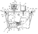
- a protection device against water splashes for electric switches and the like has been generally identified by reference numeral 1.
- the device is associated with an electric switch 2 for the purpose of inhibiting the penetration of any external agents thereinto.
- the switch 2 conventionally comprises a casing 3 made of electrically insulating material and intended for engagement with a shaped opening 22a provided in a support wall 22 of any electrical appliance (not shown) with which the switch is to be associated. Suitable resilient tabs 3a cooperate with a perimetric projection 3b of the casing 3 for fastening the switch 2 to the edge of the shaped opening 22a.
- the perimetric projection 3b is embedded in a perimetric recess 23 defined around the edges of the shaped opening 22a.
- An annular sealing element 24 engaged around the perimetric projection 3b acts between the projection and a locating housing 23a defined in the perimetric recess 23, so as to prevent water or other undesired substances from penetrating into the switch through the shaped opening 22a.
- An interconnecting device 4 operates within the casing 3 for selectively causing the opening and closure of one or more electric circuits with which the switch is associated.
- the interconnecting device 4 which is the object of an Italian Patent application filed on same date in the name of the same Applicant, comprises first and second fixed contacts, 5 and 6, rigidly carried by a base wall 7 of the casing 3 and connected to respective electric conductors, not shown as known per se and conventional.
- the first and second fixed contacts 5 cooperate with at least one movable contact element 8 that, upon the action of at least one control pushbutton 9 projecting externally of a front side 10 of the casing 9, can be selectively moved from an open condition to a closed condition, for breaking and restoring an electric continuity between the fixed contacts 5 and 6, respectively.
- the movable contact element 8 has a linking portion 11 oscillatably engaged on the first fixed contact 5 and an interconnecting portion 12 which is moved close to and away from the second fixed contact 6 when said opening and closure conditions are respectively set.
- a sealing means is provided to be associated with the switch 2 and it operates on the front side 10 of the casing 3 for ensuring a heat insulation of said casing from the surrounding atmosphere.
- this sealing means is such structured that it defines a labyrinth path capable of preventing water droplets projected against the switch 2 from penetrating thereinto.
- the sealing means comprises a closure wall 13 hermetically associated with the front side 10 of the casing 3.
- the closure wall 13, preferably of one piece construction with the casing 3 has at least one guide collar 14 projecting from the wall itself and slidably passed through by a transmission rod 15 operatively connecting the control pushbutton 9 to the movable contact element 8, as better specified in the following.
- the control pushbutton 9 has a bottom wall 16 engaged to one end 15a of the transmission rod 15 and a perimetric wall 17 sealingly fitted around the guide collar 14 possibly through interposition of at least one seal 18.
- the switch 2 with which the device 1 is associated is of the bat-handle type.
- two control pushbuttons 9 are provided each engaged on a corresponding guide collar 14 and carrying respective transmission rods 15.
- the rods 15 are linked, on mutually opposite sides, to a rocking element 19 oscillatably engaged with the casing 3 by at least one central pivot pin 20.
- the rocking element 19 is operatively connected to the movable contact element 8 via a bistable helical spring 21 acting at the linking portion 11 of the movable contact element.
- the bistable spring 21 in known manner, bends with alternate motion on opposite sides with respect to an ideal median line, thereby selectively controlling the movement of the movable contact element 8 from the open condition to the closed condition and vice-versa.
- the bistable spring 21 acting upon the movable contact element 8 also ensures that the linking portion 11 thereof is constantly held in contact with the end of the first fixed contact 5.
- the present invention attains the intended purposes.
- the device in reference in fact enables the switch to be satisfactorily protected against water splashes without the use of sealing elements made of silicone or similar materials being required.
- said materials besides encountering problems as regards reliability, also involve important increases in costs due to the particular workings for manufacturing and assembling the different additional parts.
- the present invention can be adopted on all kinds of switches, changover switches or the like, without practically involving any increase in the production costs.
- closure wall 13 can be easily formed during the moulding step for making the casing 3.
- the transmission rods 15 may also be made, if desired, unitary with the respective control pushbuttons 9 and linked to the rocking element 19 by a mere fitting action to be executed on the automated assembly lines conventionally used for making said switches.
Landscapes
- Switch Cases, Indication, And Locking (AREA)
- Push-Button Switches (AREA)
Applications Claiming Priority (2)
| Application Number | Priority Date | Filing Date | Title |
|---|---|---|---|
| IT93MI000159U IT229678Y1 (it) | 1993-02-26 | 1993-02-26 | Dispositivo di protezione contro spruzzi d'acqua per interruttori elet trici e simili |
| ITMI930159U | 1993-02-26 |
Publications (3)
| Publication Number | Publication Date |
|---|---|
| EP0613160A2 true EP0613160A2 (fr) | 1994-08-31 |
| EP0613160A3 EP0613160A3 (fr) | 1995-05-24 |
| EP0613160B1 EP0613160B1 (fr) | 1998-06-17 |
Family
ID=11364819
Family Applications (1)
| Application Number | Title | Priority Date | Filing Date |
|---|---|---|---|
| EP93830142A Expired - Lifetime EP0613160B1 (fr) | 1993-02-26 | 1993-04-02 | Protection contre les projections d'eau pour interrupteurs électriques et similaires |
Country Status (5)
| Country | Link |
|---|---|
| US (1) | US5349147A (fr) |
| EP (1) | EP0613160B1 (fr) |
| DE (1) | DE69319220T2 (fr) |
| ES (1) | ES2118215T3 (fr) |
| IT (1) | IT229678Y1 (fr) |
Cited By (2)
| Publication number | Priority date | Publication date | Assignee | Title |
|---|---|---|---|---|
| EP0777245A1 (fr) * | 1995-11-30 | 1997-06-04 | SIGNAL LUX S.p.A. | Dispositif de protection contre des infiltrations de liquides dans des interrupteurs électriques et similaires |
| US6900405B2 (en) | 2002-11-15 | 2005-05-31 | Ellenberger & Poensgen Gmbh | Sealed circuit breaker with push-pull actuation |
Families Citing this family (8)
| Publication number | Priority date | Publication date | Assignee | Title |
|---|---|---|---|---|
| DE20208683U1 (de) * | 2002-06-05 | 2002-08-14 | Bernstein AG, 32457 Porta Westfalica | Handbetätigbares, elektrisches Bedienungsteil |
| US20050010391A1 (en) * | 2003-07-10 | 2005-01-13 | International Business Machines Corporation | Chinese character / Pin Yin / English translator |
| US8904663B2 (en) * | 2003-07-24 | 2014-12-09 | The Procter & Gamble Company | Hand hair dryer with two handle grips |
| WO2007090382A2 (fr) * | 2006-02-10 | 2007-08-16 | Marquardt Gmbh | Commutateur électrique |
| DK2620228T3 (en) * | 2008-11-14 | 2017-08-21 | Kaercher Gmbh & Co Kg Alfred | Pressure Washer |
| WO2010091698A1 (fr) | 2009-02-13 | 2010-08-19 | Alfred Kärcher Gmbh & Co. Kg | Unité moteur-pompe |
| WO2010091699A1 (fr) | 2009-02-13 | 2010-08-19 | Alfred Kärcher Gmbh & Co. Kg | Unité moteur-pompe |
| DE102009010461A1 (de) | 2009-02-13 | 2010-08-19 | Alfred Kärcher Gmbh & Co. Kg | Motorpumpeneinheit |
Family Cites Families (11)
| Publication number | Priority date | Publication date | Assignee | Title |
|---|---|---|---|---|
| US2040919A (en) * | 1932-04-07 | 1936-05-19 | Engineering & Res Corp | Circuit closer |
| DE761776C (de) * | 1941-07-24 | 1951-05-21 | Busch Jaeger Luedenscheider Me | Wasserdichter Druckknopfschalter mit zwei Druckknoepfen |
| DE1790858U (de) * | 1957-11-20 | 1959-06-25 | R & A Jaeger | Feuchtigkeitsschutz bei elektrischen drucktaster-einrichtungen. |
| DE1186928B (de) * | 1963-04-20 | 1965-02-11 | Jung Albrecht Fa | Wasserdichter Wippenschalter |
| US3772484A (en) * | 1972-09-11 | 1973-11-13 | J Roeser | Dual acting push button toggle switch |
| FR2478772A1 (fr) * | 1980-03-24 | 1981-09-25 | Mayc Sa | Dispositif d'etancheite pour support de commandes par impulsion en particulier applicable aux machines a laver et a secher le linge et autres produits similaires |
| JPS6180546U (fr) * | 1984-11-01 | 1986-05-29 | ||
| US4825023A (en) * | 1986-09-22 | 1989-04-25 | Nena Morse | Armored axially displaceable sealing apparatus |
| DE3641003A1 (de) * | 1986-12-01 | 1988-06-16 | Bosch Siemens Hausgeraete | Schaltertableau eines hausgeraetes |
| US5149924A (en) * | 1989-05-05 | 1992-09-22 | Priesemuth W | Multiple contact switch arrangement |
| US5053591A (en) * | 1990-02-20 | 1991-10-01 | Eaton Corporation | Illuminated sealed rocker switch |
-
1993
- 1993-02-26 IT IT93MI000159U patent/IT229678Y1/it active IP Right Grant
- 1993-04-02 DE DE69319220T patent/DE69319220T2/de not_active Expired - Lifetime
- 1993-04-02 ES ES93830142T patent/ES2118215T3/es not_active Expired - Lifetime
- 1993-04-02 EP EP93830142A patent/EP0613160B1/fr not_active Expired - Lifetime
- 1993-07-19 US US08/093,470 patent/US5349147A/en not_active Expired - Lifetime
Cited By (3)
| Publication number | Priority date | Publication date | Assignee | Title |
|---|---|---|---|---|
| EP0777245A1 (fr) * | 1995-11-30 | 1997-06-04 | SIGNAL LUX S.p.A. | Dispositif de protection contre des infiltrations de liquides dans des interrupteurs électriques et similaires |
| EP0964418A1 (fr) * | 1995-11-30 | 1999-12-15 | SIGNAL LUX ITALIA S.p.A. | Dispositif de protection contre des infiltrations de liquides dans des interrupteurs électriques et similaires |
| US6900405B2 (en) | 2002-11-15 | 2005-05-31 | Ellenberger & Poensgen Gmbh | Sealed circuit breaker with push-pull actuation |
Also Published As
| Publication number | Publication date |
|---|---|
| EP0613160A3 (fr) | 1995-05-24 |
| DE69319220D1 (de) | 1998-07-23 |
| IT229678Y1 (it) | 1999-01-29 |
| ITMI930159V0 (it) | 1993-02-26 |
| US5349147A (en) | 1994-09-20 |
| DE69319220T2 (de) | 1998-10-22 |
| EP0613160B1 (fr) | 1998-06-17 |
| ES2118215T3 (es) | 1998-09-16 |
| ITMI930159U1 (it) | 1994-08-26 |
Similar Documents
| Publication | Publication Date | Title |
|---|---|---|
| EP0613160B1 (fr) | Protection contre les projections d'eau pour interrupteurs électriques et similaires | |
| US4820888A (en) | Tilt switch replacing mercury switches | |
| US5144516A (en) | Leakage current circuit interrupter device | |
| TW329014B (en) | Rocker Switch with Regulated Current Protection | |
| JP3009365U (ja) | 作動軸変換防水開閉装置 | |
| US6246307B1 (en) | Magnetic switch | |
| US4362910A (en) | Electrical switch | |
| US4110585A (en) | Grounded lever toggle switch | |
| EP0964418B1 (fr) | Dispositif de protection contre des infiltrations de liquides dans des interrupteurs électriques et similaires | |
| US3553720A (en) | Variable circuit timer with improved contact securing means | |
| US3541288A (en) | Splash-proof electrical switch | |
| EP0878814A1 (fr) | Commutateur avec protection contre la poussière et les embruns | |
| AU692132B1 (en) | Improvements in/or relating to electrical switches | |
| US3821531A (en) | Dust shield for plunger operated electrical switch | |
| EP0747915B1 (fr) | Interrupteur de sécurité, notamment pour des appareils électroménagers | |
| US2408157A (en) | Electric switch | |
| JP2001210190A (ja) | 電気的スイッチ | |
| CN219738824U (zh) | 一种防水开关 | |
| US3305659A (en) | Liquid diverting switch actuator | |
| US3478179A (en) | Multiposition selector switch for an enclosed electrical control station | |
| SE9504133L (sv) | Anordning vid säkerhetsbrytare | |
| US4264886A (en) | On/off switch | |
| KR0127881Y1 (ko) | 세탁기용 안전 스위치 | |
| CN212810096U (zh) | 一种自动化电力开关 | |
| US8178807B2 (en) | Electrical switch |
Legal Events
| Date | Code | Title | Description |
|---|---|---|---|
| PUAI | Public reference made under article 153(3) epc to a published international application that has entered the european phase |
Free format text: ORIGINAL CODE: 0009012 |
|
| AK | Designated contracting states |
Kind code of ref document: A2 Designated state(s): DE ES FR GB |
|
| PUAL | Search report despatched |
Free format text: ORIGINAL CODE: 0009013 |
|
| AK | Designated contracting states |
Kind code of ref document: A3 Designated state(s): DE ES FR GB |
|
| 17P | Request for examination filed |
Effective date: 19951106 |
|
| RAP1 | Party data changed (applicant data changed or rights of an application transferred) |
Owner name: GALLONE, LEONARDO Owner name: GALLONE, LYDIA CLAIRE Owner name: GALLONE, ELISA ELETTRA Owner name: GALLONE, FIAMMETTA Owner name: GALLONE, LAURA Owner name: GALLONE, MARCO Owner name: GALLONE, FLAVIO |
|
| RIN1 | Information on inventor provided before grant (corrected) |
Inventor name: CESARE, GALLONE |
|
| RAP1 | Party data changed (applicant data changed or rights of an application transferred) |
Owner name: GALLONE, LEONARDO Owner name: GALLONE, LYDIA CLAIRE Owner name: GALLONE, ELISA ELETTRA Owner name: GALLONE, FIAMMETTA Owner name: GALLONE, LAURA Owner name: GALLONE, FLAVIO |
|
| 17Q | First examination report despatched |
Effective date: 19970421 |
|
| RAP1 | Party data changed (applicant data changed or rights of an application transferred) |
Owner name: SIGNAL LUX INTERNATIONAL S.A. |
|
| RAP1 | Party data changed (applicant data changed or rights of an application transferred) |
Owner name: SIGNAL LUX INTERNATIONAL S.A. |
|
| GRAG | Despatch of communication of intention to grant |
Free format text: ORIGINAL CODE: EPIDOS AGRA |
|
| GRAG | Despatch of communication of intention to grant |
Free format text: ORIGINAL CODE: EPIDOS AGRA |
|
| GRAH | Despatch of communication of intention to grant a patent |
Free format text: ORIGINAL CODE: EPIDOS IGRA |
|
| GRAH | Despatch of communication of intention to grant a patent |
Free format text: ORIGINAL CODE: EPIDOS IGRA |
|
| GRAA | (expected) grant |
Free format text: ORIGINAL CODE: 0009210 |
|
| AK | Designated contracting states |
Kind code of ref document: B1 Designated state(s): DE ES FR GB |
|
| REF | Corresponds to: |
Ref document number: 69319220 Country of ref document: DE Date of ref document: 19980723 |
|
| ET | Fr: translation filed | ||
| REG | Reference to a national code |
Ref country code: ES Ref legal event code: FG2A Ref document number: 2118215 Country of ref document: ES Kind code of ref document: T3 |
|
| PLBE | No opposition filed within time limit |
Free format text: ORIGINAL CODE: 0009261 |
|
| STAA | Information on the status of an ep patent application or granted ep patent |
Free format text: STATUS: NO OPPOSITION FILED WITHIN TIME LIMIT |
|
| 26N | No opposition filed | ||
| REG | Reference to a national code |
Ref country code: GB Ref legal event code: IF02 |
|
| PGFP | Annual fee paid to national office [announced via postgrant information from national office to epo] |
Ref country code: FR Payment date: 20120608 Year of fee payment: 20 Ref country code: GB Payment date: 20120430 Year of fee payment: 20 |
|
| PGFP | Annual fee paid to national office [announced via postgrant information from national office to epo] |
Ref country code: ES Payment date: 20120530 Year of fee payment: 20 Ref country code: DE Payment date: 20120702 Year of fee payment: 20 |
|
| REG | Reference to a national code |
Ref country code: DE Ref legal event code: R071 Ref document number: 69319220 Country of ref document: DE |
|
| REG | Reference to a national code |
Ref country code: GB Ref legal event code: PE20 Expiry date: 20130401 |
|
| PG25 | Lapsed in a contracting state [announced via postgrant information from national office to epo] |
Ref country code: GB Free format text: LAPSE BECAUSE OF EXPIRATION OF PROTECTION Effective date: 20130401 |
|
| REG | Reference to a national code |
Ref country code: ES Ref legal event code: FD2A Effective date: 20130725 |
|
| PG25 | Lapsed in a contracting state [announced via postgrant information from national office to epo] |
Ref country code: DE Free format text: LAPSE BECAUSE OF EXPIRATION OF PROTECTION Effective date: 20130403 |
|
| PG25 | Lapsed in a contracting state [announced via postgrant information from national office to epo] |
Ref country code: ES Free format text: LAPSE BECAUSE OF EXPIRATION OF PROTECTION Effective date: 20130403 |