EP0613172A1 - Lampe fixée d'un côté - Google Patents
Lampe fixée d'un côté Download PDFInfo
- Publication number
- EP0613172A1 EP0613172A1 EP94101619A EP94101619A EP0613172A1 EP 0613172 A1 EP0613172 A1 EP 0613172A1 EP 94101619 A EP94101619 A EP 94101619A EP 94101619 A EP94101619 A EP 94101619A EP 0613172 A1 EP0613172 A1 EP 0613172A1
- Authority
- EP
- European Patent Office
- Prior art keywords
- base
- lamp
- side according
- electric lamp
- bulb
- Prior art date
- Legal status (The legal status is an assumption and is not a legal conclusion. Google has not performed a legal analysis and makes no representation as to the accuracy of the status listed.)
- Granted
Links
- 229910052736 halogen Inorganic materials 0.000 claims abstract description 44
- 150000002367 halogens Chemical class 0.000 claims abstract description 42
- 229910052751 metal Inorganic materials 0.000 claims abstract description 11
- 239000002184 metal Substances 0.000 claims abstract description 11
- 125000006850 spacer group Chemical group 0.000 claims description 12
- 210000002105 tongue Anatomy 0.000 claims description 11
- WFKWXMTUELFFGS-UHFFFAOYSA-N tungsten Chemical compound [W] WFKWXMTUELFFGS-UHFFFAOYSA-N 0.000 abstract 1
- 229910052721 tungsten Inorganic materials 0.000 abstract 1
- 239000010937 tungsten Substances 0.000 abstract 1
- ZOKXTWBITQBERF-UHFFFAOYSA-N Molybdenum Chemical compound [Mo] ZOKXTWBITQBERF-UHFFFAOYSA-N 0.000 description 4
- 238000002788 crimping Methods 0.000 description 4
- 239000011888 foil Substances 0.000 description 4
- 229910052750 molybdenum Inorganic materials 0.000 description 4
- 239000011733 molybdenum Substances 0.000 description 4
- VYPSYNLAJGMNEJ-UHFFFAOYSA-N Silicium dioxide Chemical compound O=[Si]=O VYPSYNLAJGMNEJ-UHFFFAOYSA-N 0.000 description 3
- 238000007493 shaping process Methods 0.000 description 3
- 229910000831 Steel Inorganic materials 0.000 description 2
- 239000004568 cement Substances 0.000 description 2
- 210000000078 claw Anatomy 0.000 description 2
- 125000005843 halogen group Chemical group 0.000 description 2
- 238000009434 installation Methods 0.000 description 2
- WABPQHHGFIMREM-UHFFFAOYSA-N lead(0) Chemical compound [Pb] WABPQHHGFIMREM-UHFFFAOYSA-N 0.000 description 2
- 239000010959 steel Substances 0.000 description 2
- 238000004873 anchoring Methods 0.000 description 1
- 230000006378 damage Effects 0.000 description 1
- 230000001419 dependent effect Effects 0.000 description 1
- 230000000694 effects Effects 0.000 description 1
- NJPPVKZQTLUDBO-UHFFFAOYSA-N novaluron Chemical compound C1=C(Cl)C(OC(F)(F)C(OC(F)(F)F)F)=CC=C1NC(=O)NC(=O)C1=C(F)C=CC=C1F NJPPVKZQTLUDBO-UHFFFAOYSA-N 0.000 description 1
- 238000004080 punching Methods 0.000 description 1
- 230000005855 radiation Effects 0.000 description 1
- IHQKEDIOMGYHEB-UHFFFAOYSA-M sodium dimethylarsinate Chemical class [Na+].C[As](C)([O-])=O IHQKEDIOMGYHEB-UHFFFAOYSA-M 0.000 description 1
- 238000011144 upstream manufacturing Methods 0.000 description 1
Images




Classifications
-
- H—ELECTRICITY
- H01—ELECTRIC ELEMENTS
- H01J—ELECTRIC DISCHARGE TUBES OR DISCHARGE LAMPS
- H01J61/00—Gas-discharge or vapour-discharge lamps
- H01J61/02—Details
- H01J61/30—Vessels; Containers
- H01J61/34—Double-wall vessels or containers
-
- H—ELECTRICITY
- H01—ELECTRIC ELEMENTS
- H01K—ELECTRIC INCANDESCENT LAMPS
- H01K1/00—Details
- H01K1/42—Means forming part of the lamp for the purpose of providing electrical connection, or support for, the lamp
- H01K1/46—Means forming part of the lamp for the purpose of providing electrical connection, or support for, the lamp supported by a separate part, e.g. base, cap
Definitions
- the invention relates to an electric lamp with a base on one side according to the preamble of patent claim 1.
- a lamp corresponding to the features of the preamble of claim 1 is disclosed, for example, in EP-A 0 498 256.
- the lamps described in this laid-open document have a lamp holder which consists of an annular or a helically wound metal wire. This metal wire is screwed into the base sleeve of the outer bulb and is welded via an angled end to one of the power leads of the halogen incandescent lamp led out of the lamp bulb.
- the disadvantage here is that one of the two power supply lines of the halogen incandescent lamp has to assume a holding function. As a result, forces are transmitted to the corresponding pinch seal of the lamp bulb, which, in particular in the event of vibrations during transport, can lead to destruction of the welded connection between the power supply and the molybdenum foil melted into the pinch seal.
- EP-A 0 435 393 discloses a halogen incandescent lamp which is mounted within a reflector equipped with a screw base.
- a lamp holder is used to hold the halogen incandescent lamp, which clamps around the pinch foot of the lamp bulb and is fixed to projections in the neck area of the reflector body by means of angled tabs or tongues.
- This type of anchoring of the lamp holder in the neck area of the reflector has the serious disadvantage that it requires a relatively large overall length of the lamp. Because of this disadvantage, such reflector lamps cannot readily be used as a replacement for general-purpose incandescent lamps in lamps with a screw socket.
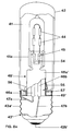
- the halogen incandescent lamp is held within the outer bulb by means of a lamp holder which is formed from a sheet metal part which clamps the lamp bulb of the halogen incandescent lamp and which is fixed in the base on the inner wall of the base sleeve.
- a lamp holder which is formed from a sheet metal part which clamps the lamp bulb of the halogen incandescent lamp and which is fixed in the base on the inner wall of the base sleeve.
- these measures enable the halogen incandescent lamp to be held securely in the outer bulb without jarring it, without stressing its power supplies.
- the lamps according to the invention Due to the fastening of the lamp holder within the base, the lamps according to the invention have a relatively short overall length, which corresponds approximately to that of conventional light bulbs.
- Suitable bases for the lamps according to the invention are the screw or bayonet bases customary for general-purpose incandescent lamps. Therefore, the lamps of the invention can be used in all lights that were originally only intended for
- the halogen incandescent lamp is advantageously held by the lamp holder on a pinch seal, since this area of the lamp bulb plays an insignificant role for the light radiation from the lamp and simple installation is possible here.
- the upper part of the lamp holder facing the lamp bulb has several tabs or holding pliers which enclose the pinch seal of the halogen incandescent lamp with a clamping effect.
- the tabs or holding tongs of the lamp holder are provided with notches, into which fit-shaped webs of the pinch seal engage, in order to further improve the fixation of the lamp bulb to the lamp holder.
- the lower part of the lamp holder is tubular, engages in the base and lies against the inner wall of the base sleeve. In this way, a play-free seat of the lamp holder in the base sleeve and a male alignment of the halogen lamp in the outer bulb are guaranteed.
- the lower part of the lamp holder is welded to the base sleeve, possibly by means of a spacer, or is equipped with a thread that allows the lamp holder to be screwed into the base sleeve.
- the latter embodiment is particularly suitable for lamps with a screw base.
- the thread is advantageously formed by isolated, specially shaped knobs or tongues, which are spread apart from the lower part of the lamp holder and claw after screwing into the thread on the inner wall of the base sleeve and thus serve to prevent it from unscrewing.
- the lamp holder has at least one angled tab, which serves as a depth stop when the lamp holder is screwed into the base sleeve and defines the vertical position of the halogen incandescent lamp in the outer bulb.
- the lamp holder has a locking device for the outer bulb, which allows the outer bulb to be fixed on the base without cement.
- the lamp holder 5 consists of a stamped sheet metal part made of Hilumin (nickel-plated steel sheet) with a thickness of approx. 0.4 mm.
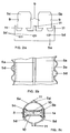
- Figure 2a shows the lamp holder 5 immediately after punching out, before the final shaping process.
- the lamp holder 5 has a tube-shaped lower part 5a, which after installation is completely sunk into the interior of the base 3 and abuts the inner wall of the base sleeve 3a.
- the upper part of the lamp holder 5 is formed by two holding pliers 5b, 5c, which are integrally formed on the lower part 5a and enclose the narrow end faces of the pinch end 1a close to the base (FIG. 2c).
- the holding tongs 5b, 5c are each provided with two notches 9 on their edge.
- notches 9 there are engaging webs 10, which are shaped to fit and run transversely to the lamp axis and are located on the surface of the pinch end 1 a near the base.
- the pinch end 1a near the base is additionally fixed in the axial direction between the holding pliers 5b, 5c.
- the outer wall of the tubular lower part 5a has three knobs 5d, which form an interrupted thread matched to the thread pitch of the E14 screw base, and enable the lamp holder 5 to be screwed or screwed into the base sleeve 3a (FIG. 2b).
- the knobs 5d are rounded in the screwing-in direction to facilitate screwing into the base sleeve 3a, while they are delimited by sharp edges in the opposite direction in order to make it difficult to unscrew the lamp holder 5 from the base sleeve 3a.
- the lower part 5a is provided with three molded, angled tabs 11 which, after the lamp carrier 5 has been screwed into the base sleeve 3a, rest on a shoulder 3c of the base sleeve 3a. These angled tabs 11 together with the paragraph 3c form one Depth stop, which defines the vertical position of the halogen incandescent lamp held in the lamp holder 5 within the outer bulb 2.
- the shoulder 3c in the interior of the base sleeve 3a serves not only the lamp holder 5, but also the neck region 2a of the outer bulb 2 cemented in the base sleeve 3a as a stop.
- the dimensions of the outer bulb 2 correspond approximately to the dimensions of a general-purpose incandescent lamp equipped with an E14 screw base.
- the second exemplary embodiment of the lamp according to the invention differs from the first exemplary embodiment described above only by a detail on the lamp carrier 5 '.
- the lamp holder 5 '(FIG. 3a) of the second exemplary embodiment has, instead of knobs, three tongues 5d' which are molded onto the tubular lower part 5a 'of the lamp holder 5' and spread outwards. These three tongues 5d 'are arranged along a thread, the pitch of which is matched to that of the E14 thread of the base sleeve 3a. They form an interrupted thread that enables the lamp holder 5 'to be screwed into the base sleeve 3a.
- the free ends 5e 'of the tongues 5d' point upwards when the lamp is oriented with the screw base 3 downward, as in FIG.
- the sharp-edged free ends 5e 'of the tongues 5d' engage in the thread on the inner wall of the base sleeve 3a, so that unscrewing is prevented (FIG. 3b).
- the second embodiment corresponds to the first.
- the lamp holder 5 ' according to the second exemplary embodiment also has two holding pliers 5b' with notches 9 'and tabs 11' angled from the lower part 5a ', the function of which was explained in more detail above in the first exemplary embodiment.
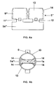
- FIGS. 4a and 4b show the lamp carrier 5 ′′ according to a third exemplary embodiment.
- FIG. 4a shows the punched-out lamp holder 5 ′′ before the final shaping process.
- the third exemplary embodiment differs from the first two exemplary embodiments only in the lamp carrier 5 ′′.
- the lamp according to the third exemplary embodiment corresponds to the first two exemplary embodiments described above.
- the lamp holder 5 '' also consists of a stamped sheet metal part. It has a tube-shaped lower part 5a ′′, which is sunk into the screw base 3 after assembly and on the inner wall the base sleeve 3a rests. Two holding parts 13 are molded onto the lower part 5a ′′ via a connecting web 12 in each case.
- Each of the two holding parts 13 forms a circular ring segment, the diameter of which corresponds to that of the tubular lower part 5a ′′.
- Both holding parts 13 each have two inward fastening tabs 14, between which the pinch end 1 a of the high-voltage halogen incandescent lamp which is close to the base is clamped.
- the fastening tabs 14 are each provided with a notch 9 ′′, which are matched to the webs 10 running transversely to the lamp axis at the pinch end 1 a of the halogen incandescent lamp.
- the lamp carrier 5 ′′ is provided with two angled, outwardly directed tabs 11 '' which, after assembly, rest on the shoulder 3c of the base sleeve 3a and serve as a depth stop for the lamp holder 5 ''.
- these tabs are welded to the socket sleeve 3a, in particular to the heel 3c, after inserting the halogen incandescent lamp held in the lamp holder 5 ′′ into the screw base 3.
- One of the two holding parts 13 is also welded to the return 8, so that an electrically conductive connection is established between the power supply 6b remote from the base and the base sleeve 3a.
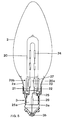
- FIG. 5 shows a fourth exemplary embodiment of an electric lamp with a base on one side according to the invention.
- the essential difference from the first three exemplary embodiments is that in this exemplary embodiment, instead of a tubular lamp, a high-voltage halogen incandescent lamp with a lamp bulb 20 that is only pinched on one side is used.
- the lamp bulb 20 is made of quartz glass and has a gas-tightly closed pinch end 20a.
- Two power leads 21, 22 protrude from the crimping end 20a, each of which is electrically conductively connected to the luminous element of the halogen incandescent lamp via a molybdenum foil 23 melted into the crimping end 20a.
- the luminous element consists of a plurality of incandescent filament sections 24 which are connected to one another in an electrically conductive manner.
- the pinch end 20a has a weakly double T-shaped profile.
- the halogen incandescent lamp is held in an axial position within the outer bulb 2 by means of a one-piece lamp holder 25, which clamps the pinching end 20a of the lamp bulb 20 and is fixed to the base sleeve.
- the outer bulb 2 is cemented with its neck region 2a into the metallic base sleeve 3a of an E14 screw base 3.
- the screw base 3 and the outer bulb 2 of this fourth embodiment correspond to those of the exemplary embodiments described above and therefore have the same reference symbols in FIG.
- a first power supply line 21 is welded to the lamp support 25 via an angled end and makes electrical contact with the base sleeve 3a, while the other power supply line 22 is electrically conductively connected to the bottom contact 3b of the screw base 3 via a fuse 26.
- FIGS. 6a and 6b Details of the lamp holder 25 of this fourth exemplary embodiment are shown in FIGS. 6a and 6b.
- the lamp holder 25 consists of a stamped sheet metal part made of Hilumin (nickel-plated steel sheet).
- FIG. 6a shows the punched-out lamp holder 25 before the final shaping process.
- the lamp holder 25 has a tubular or circular-cylindrical lower part 25a, which is sunk into the screw base 3 after assembly and abuts the inner wall of the base sleeve 3a.
- Two holding parts 25b are molded onto the lower part 25a via a connecting web 26 in each case. Both holding parts 25b each form a circular ring segment, the diameter of which corresponds to that of the tubular lower part 25a.
- both holding parts 25b each have two inwardly directed fastening tabs 27, between which the pinch end 20a of the halogen incandescent lamp is held in a clamping manner.
- the lower part 25a of the lamp holder 25 has three tongues 28 which are arranged along a thread whose pitch is matched to that of the E14 thread of the base sleeve 3a.
- the free ends of these tongues 28 point upward when the lamp, as in FIG. 5, is oriented with the screw base 3 downward.
- the tongues 28 form an interrupted thread that enables the lamp holder 25 to be screwed into the base sleeve 3a.
- the tapered, sharp-edged free ends of the tongues 28 claw in the thread on the inner wall of the base sleeve 3a, so that unscrewing is made difficult.
- the lamp support 25 is provided with two angled tabs 29 which, after assembly, rest on the shoulder 3c of the base sleeve 3a and serve as a depth stop.
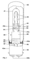
- FIG. 7 schematically shows a fifth exemplary embodiment of an electric lamp according to the invention. It consists of a high-voltage halogen incandescent lamp pinched on one side with a lamp bulb 41 made of quartz glass, which is arranged axially within a translucent, cylindrical outer bulb 42.
- the outer bulb 42 has an open end with a narrowed neck region 42a which is cemented into the socket sleeve 43a of a B22d bayonet socket 43.
- the two power supply lines in turn are each led via a fuse 46 and a lead wire 47 to a ground contact 43b of the base 43.
- a metal lamp holder 48 in which the pinched end 41a of the halogen lamp is fixed, holds the halogen lamp.
- the lamp holder 48 consists of a nickel-plated stamped sheet metal part (thickness approx. 0.4 mm) and has a tubular lower part 48a which engages in an annular spacer 49 and is welded to it.
- the annular spacer 49 has a channel-like profile. Its upward curved outer edge is welded to the base sleeve 43a.
- the narrowed neck area 42a of the outer bulb 42 lies on the bottom of the spacer 49 and is fastened there by means of putty 50.
- Two holding parts 51a, 51b each with two fastening tabs 52 directed inwards, are molded onto the tubular lower part 48a of the lamp holder 48.
- the crimping end 41a of the halogen incandescent lamp is held between the two holding parts 51a, 51b after assembly.
- the inward fastening tabs 52 press against the broad sides of the pinch end 41a.
- the fastening tabs 52 have notches 53, into which a web 54, which is integrally formed on the crimping end 41a, engages so that the halogen incandescent lamp is fixed in the axial direction.
- the holding parts 51a, 51b engage in the double-T-shaped profile of the pinch end 41a in such a way that an axial alignment of the halogen incandescent lamp in the outer bulb 42 is ensured.
- FIGS. 7, 8a and 8b show a sixth embodiment of an electric lamp according to the invention. This embodiment corresponds in many details to that of the fifth embodiment. For this reason, identical parts in FIGS. 7, 8a and 8b also have the same reference symbols in both exemplary embodiments.
- the working examples five and six differ only in the base, the lamp holder and the shape of the open end 42a ′ of the outer bulb 42.
- the base 43 ' is an E27 screw base.
- One of the current leads protruding from the squeezing end 41a is electrically conductively connected to the metallic base sleeve 43a 'via a fuse 46a and a lead wire 47a, while the other current lead 47b, also via a fuse 46b, is led to the ground contact 43b' of the base 43 '.
- the high-voltage halogen incandescent lamp is identical to that of the previous exemplary embodiment and is held by the lamp holder 48 '.
- the lamp holder 48 ' consists of a stamped sheet metal part (thickness: 0.4 mm) and has a tubular lower part 48a', to which two holding parts 51a, 51b are formed, between which the pinch end 41a of the halogen incandescent lamp is fixed. These holding parts 51a, 51b correspond to those of the fifth exemplary embodiment in all details.
- the lower part 48a 'of the lamp holder 48' engages in the annular spacer 49 'and is welded to it, as already described in the previous exemplary embodiment.
- the spacer 49 ' also has a channel-like profile here and is also welded to the inner wall of the base sleeve 43a'.
- the spacer 49 ′ has a horizontally running contact surface 57 for the outer bulb 42.
- the outer bulb 42 is fastened here in the sixth exemplary embodiment without using cement on the base 43 '.
- six catch springs 55 are used, which are arranged on the lower part 48a' of the lamp holder 48 'evenly along its circumference. These detent springs 55 protrude from the lateral surface of the lower part 48a '. Since the diameter of the outer bulb opening 42a 'is only slightly larger than the diameter of the lower part 48a', the outer bulb 42 slides over the lamp holder 48 'when it is socked up, briefly presses the detent springs 55 back and snaps between the detent springs 55 and the support surface 57 of the spacer 49 'a.
- the six detent springs 55 of which only three are shown in FIG. 8b, and the contact surface 57 enable a cementless connection between the outer bulb 42 and the base 43 '.
- the lower part 48a 'of the lamp holder 48' has two lugs 56 protruding from its outer surface and the outer bulb in the region of its opening 42a 'has two Notches matched to the lugs 56, which together form an anti-rotation device for the outer piston 42, so that rotations of the outer piston 42 about its axis are prevented.
- the invention is not limited to the exemplary embodiments described in more detail above.
- the lamp holder of the third exemplary embodiment can also be used together with a bayonet base.
Landscapes
- Fastening Of Light Sources Or Lamp Holders (AREA)
- Common Detailed Techniques For Electron Tubes Or Discharge Tubes (AREA)
- Non-Portable Lighting Devices Or Systems Thereof (AREA)
Applications Claiming Priority (2)
| Application Number | Priority Date | Filing Date | Title |
|---|---|---|---|
| DE4305503 | 1993-02-23 | ||
| DE4305503A DE4305503A1 (de) | 1993-02-23 | 1993-02-23 | Einseitig gesockelte elektrische Lampe |
Publications (2)
| Publication Number | Publication Date |
|---|---|
| EP0613172A1 true EP0613172A1 (fr) | 1994-08-31 |
| EP0613172B1 EP0613172B1 (fr) | 1996-07-17 |
Family
ID=6481112
Family Applications (1)
| Application Number | Title | Priority Date | Filing Date |
|---|---|---|---|
| EP94101619A Expired - Lifetime EP0613172B1 (fr) | 1993-02-23 | 1994-02-02 | Lampe fixée d'un cÔté |
Country Status (5)
| Country | Link |
|---|---|
| US (1) | US5453655A (fr) |
| EP (1) | EP0613172B1 (fr) |
| JP (1) | JP3283685B2 (fr) |
| KR (1) | KR100282092B1 (fr) |
| DE (2) | DE4305503A1 (fr) |
Cited By (1)
| Publication number | Priority date | Publication date | Assignee | Title |
|---|---|---|---|---|
| DE202008012461U1 (de) | 2008-09-19 | 2008-12-04 | Osram Gesellschaft mit beschränkter Haftung | Elektrische Lampe |
Families Citing this family (17)
| Publication number | Priority date | Publication date | Assignee | Title |
|---|---|---|---|---|
| DE19709928A1 (de) * | 1997-03-11 | 1998-09-17 | Patent Treuhand Ges Fuer Elektrische Gluehlampen Mbh | Halogenglühlampe und Fassung |
| US6661168B1 (en) | 2000-05-05 | 2003-12-09 | Illumination Technology, Inc. | Low voltage incandescent lamp with dual envelope |
| US20020101144A1 (en) * | 2001-01-26 | 2002-08-01 | Pan Wun Fang | Christmas bulb structure |
| US6791250B2 (en) * | 2002-10-23 | 2004-09-14 | Eye Lighting International | Seal and flag assembly for lamp base sidewire welding |
| KR20060029617A (ko) * | 2003-06-17 | 2006-04-06 | 코닌클리즈케 필립스 일렉트로닉스 엔.브이. | 외피부와 캡부를 포함하는 램프 |
| DE102004044364A1 (de) * | 2004-09-10 | 2006-03-16 | Patent-Treuhand-Gesellschaft für elektrische Glühlampen mbH | Glühlampe |
| US20080074057A1 (en) * | 2004-09-10 | 2008-03-27 | Koninklijke Philips Electronics, N.V. | Halogen Lamps |
| DE102004049500A1 (de) * | 2004-10-11 | 2006-04-20 | Patent-Treuhand-Gesellschaft für elektrische Glühlampen mbH | Lampe mit Einbaulampe |
| DE102005051076A1 (de) * | 2005-10-25 | 2007-04-26 | Patent-Treuhand-Gesellschaft für elektrische Glühlampen mbH | Lampe mit Einbaulampe |
| DE202006003314U1 (de) * | 2006-03-02 | 2006-05-18 | Patent-Treuhand-Gesellschaft für elektrische Glühlampen mbH | Lampe mit einer Einbaulampe |
| US7234973B1 (en) | 2006-03-23 | 2007-06-26 | Shelly Mark E | Lighting system having modified light bulb base and luminare socket for preventing the selection of an over wattage light bulb and method of forming same |
| DE102006014294A1 (de) * | 2006-03-28 | 2007-10-04 | Patent-Treuhand-Gesellschaft für elektrische Glühlampen mbH | Elektrische Lampe |
| CN101568989A (zh) * | 2006-12-22 | 2009-10-28 | 皇家飞利浦电子股份有限公司 | 加帽的电灯 |
| DE102007035594A1 (de) * | 2007-07-30 | 2009-02-05 | Osram Gesellschaft mit beschränkter Haftung | Elektrische Lampe mit einem Außenkolben und einer in einem Lampenträger gehaltenen Einbaulampe sowie Verfahren zu deren Herstellung |
| DE102007035595A1 (de) * | 2007-07-30 | 2009-02-05 | Osram Gesellschaft mit beschränkter Haftung | Elektrische Lampe mit einem Außenkolben und einer Einbaulampe sowie ein Verfahren zu deren Herstellung |
| DE102008030547A1 (de) * | 2008-06-27 | 2009-12-31 | Osram Gesellschaft mit beschränkter Haftung | Elektrische Lampe mit einem Außenkolben und einer Einbaulampe |
| EP2458614B1 (fr) * | 2010-11-25 | 2014-04-02 | OSRAM GmbH | Lampe électrique comprenant une ampoule extérieure et une lampe intégrée |
Citations (5)
| Publication number | Priority date | Publication date | Assignee | Title |
|---|---|---|---|---|
| DE1489414A1 (de) * | 1963-01-28 | 1969-03-06 | Philips Nv | Elektrische Lampe |
| US3676835A (en) * | 1971-02-01 | 1972-07-11 | Hollymatic Corp | Electrical connector |
| EP0435393A1 (fr) * | 1989-12-27 | 1991-07-03 | Koninklijke Philips Electronics N.V. | Lampe et réflecteur |
| US5043624A (en) * | 1988-12-01 | 1991-08-27 | Koito Manufacturing Co., Ltd. | Electric lamp assembly having a band connected to integrally formed metal pieces on a base |
| EP0498256A2 (fr) * | 1991-02-08 | 1992-08-12 | Patent-Treuhand-Gesellschaft für elektrische Glühlampen mbH | Lampe fixée d'un côté |
Family Cites Families (6)
| Publication number | Priority date | Publication date | Assignee | Title |
|---|---|---|---|---|
| US4569005A (en) * | 1985-01-15 | 1986-02-04 | Gte Products Corporation | Replaceable lamp unit and automobile headlight utilizing same |
| US5053935A (en) * | 1989-08-21 | 1991-10-01 | U.S. Philips Corporation | Lamp/reflector unit |
| US5146134A (en) * | 1990-03-15 | 1992-09-08 | Patent Treuhand Gesellschaft Fur Elektrische Gluhlampen M.B.H. | Halogen incandescent lamp, particularly for operation from power networks, and method of its manufacture |
| DE9012292U1 (de) * | 1990-08-27 | 1990-10-31 | Patent-Treuhand-Gesellschaft für elektrische Glühlampen mbH, 8000 München | Kittlos gesockelte elektrische Lampe |
| US5239226A (en) * | 1990-12-14 | 1993-08-24 | General Electric Company | Replaceable lamp assembly for automotive headlamps |
| MX9202270A (es) * | 1991-05-31 | 1992-11-01 | Philips Nv | Lampara de reflector electrico. |
-
1993
- 1993-02-23 DE DE4305503A patent/DE4305503A1/de not_active Withdrawn
-
1994
- 1994-02-02 DE DE59400420T patent/DE59400420D1/de not_active Expired - Fee Related
- 1994-02-02 EP EP94101619A patent/EP0613172B1/fr not_active Expired - Lifetime
- 1994-02-17 US US08/197,693 patent/US5453655A/en not_active Expired - Fee Related
- 1994-02-21 JP JP04774694A patent/JP3283685B2/ja not_active Expired - Fee Related
- 1994-02-21 KR KR1019940003026A patent/KR100282092B1/ko not_active Expired - Fee Related
Patent Citations (5)
| Publication number | Priority date | Publication date | Assignee | Title |
|---|---|---|---|---|
| DE1489414A1 (de) * | 1963-01-28 | 1969-03-06 | Philips Nv | Elektrische Lampe |
| US3676835A (en) * | 1971-02-01 | 1972-07-11 | Hollymatic Corp | Electrical connector |
| US5043624A (en) * | 1988-12-01 | 1991-08-27 | Koito Manufacturing Co., Ltd. | Electric lamp assembly having a band connected to integrally formed metal pieces on a base |
| EP0435393A1 (fr) * | 1989-12-27 | 1991-07-03 | Koninklijke Philips Electronics N.V. | Lampe et réflecteur |
| EP0498256A2 (fr) * | 1991-02-08 | 1992-08-12 | Patent-Treuhand-Gesellschaft für elektrische Glühlampen mbH | Lampe fixée d'un côté |
Cited By (1)
| Publication number | Priority date | Publication date | Assignee | Title |
|---|---|---|---|---|
| DE202008012461U1 (de) | 2008-09-19 | 2008-12-04 | Osram Gesellschaft mit beschränkter Haftung | Elektrische Lampe |
Also Published As
| Publication number | Publication date |
|---|---|
| DE59400420D1 (de) | 1996-08-22 |
| US5453655A (en) | 1995-09-26 |
| EP0613172B1 (fr) | 1996-07-17 |
| KR100282092B1 (ko) | 2001-03-02 |
| JP3283685B2 (ja) | 2002-05-20 |
| DE4305503A1 (de) | 1994-08-25 |
| KR940020462A (ko) | 1994-09-16 |
| JPH06260151A (ja) | 1994-09-16 |
Similar Documents
| Publication | Publication Date | Title |
|---|---|---|
| EP0613172B1 (fr) | Lampe fixée d'un cÔté | |
| EP0835521B1 (fr) | Lampe electrique | |
| DE9101460U1 (de) | Einseitig gesockelte elektrische Lampe | |
| DE29910604U1 (de) | Reflektorlampe | |
| DE3609908A1 (de) | Halogengluehlampe und verfahren zu ihrer herstellung | |
| DE69505798T2 (de) | Elektrische lampe | |
| EP0078030B1 (fr) | Lampe électrique | |
| EP0758142A2 (fr) | Lampe à incandescence halogène | |
| EP0944112B1 (fr) | Lampe à incandescence halogène, lampe électrique et procédé de fabrication d'une lampe à incandescense halogène | |
| EP1006550B1 (fr) | Lampe électrique et dispositif d'éclairage avec une telle lampe électrique | |
| DE2817105C2 (de) | Hochspannungsstecker für Kathodenstrahlröhren | |
| EP1679736A2 (fr) | Lampe avec une lampe encastrée | |
| EP1435636A2 (fr) | Unité d'éclairage | |
| EP0854497A2 (fr) | Lampe compacte à décharge basse pression | |
| DE69110097T2 (de) | Elektrische Glühlampe. | |
| DE69323595T2 (de) | Innerer Teil eines Lampengehäuses | |
| DE102010002650B4 (de) | Halogenglühlampe für Fahrzeugscheinwerfer | |
| EP1714306B1 (fr) | Ampoule de phare de vehicule | |
| DE4230815A1 (de) | Hochdruckentladungslampe und Herstellungsverfahren für eine Hochdruckentladungslampe | |
| EP1009012A1 (fr) | Lampe électrique | |
| DE3406775A1 (de) | Elektrische lampe mit selbsthalternder rahmenbaugruppe und verfahren zu ihrer herstellung | |
| EP1116254B1 (fr) | Lampe electrique | |
| EP2399268A1 (fr) | Lampe électrique comportant un piston extérieur et une lampe intégrée | |
| EP2122241B1 (fr) | Bague de fixation | |
| AT228338B (de) | Elektrische Lampe |
Legal Events
| Date | Code | Title | Description |
|---|---|---|---|
| PUAI | Public reference made under article 153(3) epc to a published international application that has entered the european phase |
Free format text: ORIGINAL CODE: 0009012 |
|
| AK | Designated contracting states |
Kind code of ref document: A1 Designated state(s): BE DE FR GB IT NL |
|
| 17P | Request for examination filed |
Effective date: 19940915 |
|
| 17Q | First examination report despatched |
Effective date: 19951020 |
|
| GRAH | Despatch of communication of intention to grant a patent |
Free format text: ORIGINAL CODE: EPIDOS IGRA |
|
| GRAH | Despatch of communication of intention to grant a patent |
Free format text: ORIGINAL CODE: EPIDOS IGRA |
|
| GRAA | (expected) grant |
Free format text: ORIGINAL CODE: 0009210 |
|
| AK | Designated contracting states |
Kind code of ref document: B1 Designated state(s): BE DE FR GB IT NL |
|
| REF | Corresponds to: |
Ref document number: 59400420 Country of ref document: DE Date of ref document: 19960822 |
|
| ITF | It: translation for a ep patent filed | ||
| GBT | Gb: translation of ep patent filed (gb section 77(6)(a)/1977) |
Effective date: 19960923 |
|
| ET | Fr: translation filed | ||
| PLBE | No opposition filed within time limit |
Free format text: ORIGINAL CODE: 0009261 |
|
| STAA | Information on the status of an ep patent application or granted ep patent |
Free format text: STATUS: NO OPPOSITION FILED WITHIN TIME LIMIT |
|
| 26N | No opposition filed | ||
| REG | Reference to a national code |
Ref country code: GB Ref legal event code: IF02 |
|
| PGFP | Annual fee paid to national office [announced via postgrant information from national office to epo] |
Ref country code: GB Payment date: 20060209 Year of fee payment: 13 |
|
| PGFP | Annual fee paid to national office [announced via postgrant information from national office to epo] |
Ref country code: BE Payment date: 20060214 Year of fee payment: 13 |
|
| PGFP | Annual fee paid to national office [announced via postgrant information from national office to epo] |
Ref country code: NL Payment date: 20060215 Year of fee payment: 13 |
|
| PGFP | Annual fee paid to national office [announced via postgrant information from national office to epo] |
Ref country code: FR Payment date: 20060220 Year of fee payment: 13 |
|
| PGFP | Annual fee paid to national office [announced via postgrant information from national office to epo] |
Ref country code: IT Payment date: 20060228 Year of fee payment: 13 |
|
| GBPC | Gb: european patent ceased through non-payment of renewal fee |
Effective date: 20070202 |
|
| NLV4 | Nl: lapsed or anulled due to non-payment of the annual fee |
Effective date: 20070901 |
|
| REG | Reference to a national code |
Ref country code: FR Ref legal event code: ST Effective date: 20071030 |
|
| BERE | Be: lapsed |
Owner name: *PATENT-TREUHAND-G.- FUR ELEKTRISCHE GLUHLAMPEN M. Effective date: 20070228 |
|
| PG25 | Lapsed in a contracting state [announced via postgrant information from national office to epo] |
Ref country code: BE Free format text: LAPSE BECAUSE OF NON-PAYMENT OF DUE FEES Effective date: 20070228 |
|
| PG25 | Lapsed in a contracting state [announced via postgrant information from national office to epo] |
Ref country code: NL Free format text: LAPSE BECAUSE OF NON-PAYMENT OF DUE FEES Effective date: 20070901 |
|
| PG25 | Lapsed in a contracting state [announced via postgrant information from national office to epo] |
Ref country code: GB Free format text: LAPSE BECAUSE OF NON-PAYMENT OF DUE FEES Effective date: 20070202 Ref country code: FR Free format text: LAPSE BECAUSE OF NON-PAYMENT OF DUE FEES Effective date: 20070228 |
|
| PGFP | Annual fee paid to national office [announced via postgrant information from national office to epo] |
Ref country code: DE Payment date: 20090420 Year of fee payment: 16 |
|
| PG25 | Lapsed in a contracting state [announced via postgrant information from national office to epo] |
Ref country code: IT Free format text: LAPSE BECAUSE OF NON-PAYMENT OF DUE FEES Effective date: 20070202 |
|
| PG25 | Lapsed in a contracting state [announced via postgrant information from national office to epo] |
Ref country code: DE Free format text: LAPSE BECAUSE OF NON-PAYMENT OF DUE FEES Effective date: 20100901 |