EP0613802A1 - Modularer Flüssigkeitsverteiler und seine Anwendung insbesondere für eine Autositzverstellung - Google Patents
Modularer Flüssigkeitsverteiler und seine Anwendung insbesondere für eine Autositzverstellung Download PDFInfo
- Publication number
- EP0613802A1 EP0613802A1 EP94400283A EP94400283A EP0613802A1 EP 0613802 A1 EP0613802 A1 EP 0613802A1 EP 94400283 A EP94400283 A EP 94400283A EP 94400283 A EP94400283 A EP 94400283A EP 0613802 A1 EP0613802 A1 EP 0613802A1
- Authority
- EP
- European Patent Office
- Prior art keywords
- rocker
- guillotine
- housing
- flange
- distributor according
- Prior art date
- Legal status (The legal status is an assumption and is not a legal conclusion. Google has not performed a legal analysis and makes no representation as to the accuracy of the status listed.)
- Granted
Links
- 239000007788 liquid Substances 0.000 title claims abstract description 8
- 239000012530 fluid Substances 0.000 claims abstract description 18
- 238000007789 sealing Methods 0.000 claims description 11
- 238000005192 partition Methods 0.000 claims description 7
- 238000004891 communication Methods 0.000 claims description 5
- 230000000694 effects Effects 0.000 claims description 5
- 239000007787 solid Substances 0.000 claims description 5
- 230000000295 complement effect Effects 0.000 claims description 3
- 241000289659 Erinaceidae Species 0.000 description 1
- 241000289669 Erinaceus europaeus Species 0.000 description 1
- 238000004026 adhesive bonding Methods 0.000 description 1
- 238000004519 manufacturing process Methods 0.000 description 1
- 238000000034 method Methods 0.000 description 1
- 238000000465 moulding Methods 0.000 description 1
- 210000000056 organ Anatomy 0.000 description 1
- 229920002994 synthetic fiber Polymers 0.000 description 1
- 238000013519 translation Methods 0.000 description 1
- 230000014616 translation Effects 0.000 description 1
- 238000003466 welding Methods 0.000 description 1
Images



Classifications
-
- B—PERFORMING OPERATIONS; TRANSPORTING
- B60—VEHICLES IN GENERAL
- B60N—SEATS SPECIALLY ADAPTED FOR VEHICLES; VEHICLE PASSENGER ACCOMMODATION NOT OTHERWISE PROVIDED FOR
- B60N2/00—Seats specially adapted for vehicles; Arrangement or mounting of seats in vehicles
- B60N2/90—Details or parts not otherwise provided for
- B60N2/914—Hydro-pneumatic adjustments of the shape
-
- F—MECHANICAL ENGINEERING; LIGHTING; HEATING; WEAPONS; BLASTING
- F15—FLUID-PRESSURE ACTUATORS; HYDRAULICS OR PNEUMATICS IN GENERAL
- F15B—SYSTEMS ACTING BY MEANS OF FLUIDS IN GENERAL; FLUID-PRESSURE ACTUATORS, e.g. SERVOMOTORS; DETAILS OF FLUID-PRESSURE SYSTEMS, NOT OTHERWISE PROVIDED FOR
- F15B13/00—Details of servomotor systems ; Valves for servomotor systems
- F15B13/02—Fluid distribution or supply devices characterised by their adaptation to the control of servomotors
Definitions
- the present invention relates to a distributor for liquid fluid and, more particularly, to a modular guillotine distributor with at least one channel and at least single-acting, and also, in particular, its application to adjusting the position of a land vehicle seat. with fluid actuator.
- actuators driven by a liquid, hydraulic or other fluid, pressurized using a motor pump for example to move devices or organs which describe translations and / or rotations. .
- the object of the invention is to make a modular guillotine distributor with at least one channel and at least single effect to, for example, allow the selective implementation of at least one cylinder in at least one direction.
- the subject of the invention is a modular guillotine distributor with at least one channel and at least single effect for liquid fluid.
- This dispenser is remarkable in that it comprises a body consisting of at least one group made, on the one hand, of a housing forming an internal cylindrical cavity with a partition which is pierced by two diametrically opposite axial manholes and which is delimited by two opposite sides, one of which is provided with two symmetrical bowls in an arc of a circle whose concavity is directed towards the outside and which are arranged in quadrature relative to the manholes so that their ends are located on the same circle that the latter, and with a border which has two opposite free sections each provided with slots forming solid and hollow and which is pierced by two practically radial pipes diametrically opposed which each open into one of the bowls and, on the other hand, housed at least partially in this cavity a rocker forming a cylindrical wafer which is movable between a rest position in laq uelle it is normally maintained and at
- the dispenser according to the invention is of a type which is suitable for its application for adjusting the position of a seat of a land motor vehicle driven by an actuator of the type of a double V cylinder. effect.
- a modular guillotine distributor according to the invention comprises a body 10 consisting of at least one group made of a housing 11 and a rocker 12, a flange 20 at each end of the body 10, a stress elastic 30, a sealing arrangement 40, connecting means 50, a fixing device 60 and, preferably, a safety device 70.
- a housing 11 essentially comprises a partition 111 and an edge 112.
- the housing 11 delimits an internal cylindrical cavity 100.
- the partition 111 is pierced by two axial manholes 1110, preferably diametrically opposite, and is delimited by two opposite sides 1111 and 1112.
- the side 1111, or front side in FIG. 2 is provided with there is the sealing arrangement 40.
- the other side 1112, or back, is provided with two cuvettes 101 preferably symmetrical and in an arc, the concavity of which is directed towards the outside.
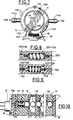
- the bowls 101 are arranged in quadrature relative to the manholes 1110 so that the ends or horns of the bowls are located on the same circle as the manholes. This is clearly illustrated in particular in Figure 2 of the drawing. As will be understood later, these manholes and bowls are such that one is used for the inlet (A) and the other for the return (R) of the fluid.
- the border 112 has two free, opposite edges 1120, which are each provided with slots 1121 forming solid and hollow in the manner of merlons and embrasures, respectively.
- the free sections are also each provided with a recess 1122 preferably double and a notch 1123 to which we will return.
- the border 1120 is also pierced by two tubes 1100, preferably practically radial and diametrically opposite, which each open into one of the bowls 101.
- These tubes are also provided, outside, with connectors 1103 fitted with end caps "hedgehog" for example of any suitable type for the reasons which will be understood later.
- One of these pipes is intended for the inlet (A) and the other for the return (R) of the fluid as will be understood later, after connection to the jack V. This is clearly shown in Figures 2, 11 and 12 in particular.
- the rocker 12 which is movable between a rest position and at least one active position, comprises a wall 121 and a control 122.
- the rocker 12 in the form of a cylindrical wafer has its wall 121 which is pierced by two passages 1210 preferably diametrically axial opposite, and is bounded by two sides.
- One side 1211 or front which is for example equipped with a sealing arrangement 40, and which is provided with two bowls 102 preferably symmetrical in an arc of a circle whose concavity is directed towards the outside and which are arranged relative to the passages 1210 so that each of them partially surrounds one of these passages and so that the ends or horns are arranged in the same circle as the passages.
- this side is also provided with a discharge 103 to which we will return later.
- These passages and bowls are such that some are intended for the inlet (A) and the others for the return (R) of the fluid.
- the other side 1212 or back is equipped if necessary with a sealing arrangement 40.
- the control 122 preferably visible radial comprises a lever 1220 which is equipped with a head 1221 for operation and a junction foot 1222 which connects the head to the wall.
- the operating head is superficially striated or otherwise configured so as to facilitate handling thereof, for example using a finger, as will be understood later.
- the operating head is provided with descriptive or other figurines, indicative of the adjustment operation and of the direction of the latter.
- the illustrated embodiment of the dispenser according to the invention makes it possible to adjust, in two opposite directions, the longitudinal and vertical position of the seat of a seat and the inclination of its folder.
- the junction foot 1222 is also pierced with an opening 1223.
- the junction foot 1222 is intended to move in a circulation corridor which is delimited by two notches 1122 facing each other. screw.
- the flange 20 comprises a bottom 21 and a border 22.
- the flange 20 delimits a cavity 200 inner cylindrical.
- the bottom 21 is pierced with at least one orifice 210, for example axial, and preferably two for the circulation of the fluid, one serving for the intake (A) and the other for the discharge (R) of the latter.
- This background is delimited by two opposite faces 211 and 212.
- the inside or front face 211 is for example intended to be equipped with a sealing arrangement 40 and the outside or back face 212 is provided with fittings 213, each associated with an orifice 210, which are in the form of end caps with "hedgehogs" or the like of any suitable type.
- the edge 22 has a free edge 220 provided with slots 221 forming solid and hollow, such as merlons and embrasures.
- the slots 221 are complementary to the slots 1121 of the free edge 1120 of the edge 112 of the housing 11, with which they are intended to cooperate in order to become entangled, as will be understood hereinafter.
- the flange 20 defines the internal cylindrical cavity 200 which, with the cavity 100 of the housing 11, together delimits an enclosure where the rocker 12 is housed and where the rocker 12 can rotate.
- the elastic stress 30 is for example made of a coil spring with turns wound according to a cylindrical helix.
- the coil spring is placed in the opening 1223 of the junction foot of the lever of the rocker control and is engaged in the notches 223 of the edge of the flange 20 and in the notches 1123 of the edge of the housing 11. This is clearly illustrated in particular in Figures 8 and 9.
- This elastic stress normally maintains the rocker 12 in its rest position and it is necessary to act against it to place the rocker in one or the other of its two active positions which are separated by the rest position, as will be understood later.
- the sealing arrangement 40 comprises at at least one groove 41 or groove, for example with a triangular profile in cross section, formed in at least one of the interior or front faces 211 of the bottom of a flange and / or in at least one of the opposite sides 1111 and 1112 of the housing partition and 1211 and 1212 of the rocker wall.
- a seal 42 for example an appropriate O-ring, is housed in the groove 41. This is conventional and is clearly illustrated in the figures of the drawing, in particular Figures 2 and 13.
- the connecting means 50 keep the flanges 20 and the body 10 grouped together in a sealed entity in which a rocker 12 can move.
- These connecting means 50 comprise, for example, at least one depression 51 on the external surface 212 of the bottom 21 of each flange 20, and a clamp 52 in the form of a clamp whose approximately parallel branches are engaged with two bosses at opposite depression. This is clearly illustrated in particular in Figures 1 and 4 of the drawing. It is clear that instead of using a type of elastic stapling connection means, it is possible to use tie rods or the like, or even suitable screwing, riveting, gluing or welding techniques.
- the fixing device 60 makes it possible to subject the dispenser according to the invention to a support intended to receive it with a view to its use, for example on board a vehicle.
- This fixing device comprises for example at least one lug 61 or the like on the external face 212 of the bottom 21 of at least one flange 20, and at least one hole 62 or the like made in this lug for placing a rivet, a screw therein. or similar for example.
- a safety device 70 which prohibits the simultaneous operation of more than one rocker at a time.
- This security which is for example of the type described in document FR 92-11277 to which reference will usefully be made for more details, essentially comprises a channel 71 consisting of sections 710 which are formed in the partitions 111 and walls 121 and are aligned, and in which are housed balls 72, a spring 73, a movable stop 74 whose tail 740 acts on a control member 750 of a sensor 75.
- the sensor 75 which is actuated regardless of which of the rockers 12 is operated and whatever the direction, makes it possible to operate the motor pump of a hydraulic unit which puts the liquid fluid circuit under pressure to drive the actuators such as double-acting V cylinders .
- the various components of a dispenser according to the invention are, for example, made of synthetic materials shaped for example by molding.
- FIGS. 8 and 9 On the one hand, and 11 and 12, on the other hand.
- the dispenser according to the invention occupies the configuration where it is illustrated in Figures 8 and 11. It can then be seen that the elastic biasing device is such that the spring occupies the entire housing delimited by two notches facing each other ( Figure 8). In this situation, the orifices 210 at the bottom of a flange, the manholes 1110 of the housing and the passages 1210 of the rocker are all aligned with each other. We see that the cups 101 of the housing and 102 of the rocker are not in communication and so it is the same with the pipes 1100 with the orifices 210 of the flange which are thus isolated from each other. On the other hand, the pressurization motor is not supplied. This is the situation illustrated in Figure 11.
- rocker 12 in one direction or the other, to move it against the elastic stress, we compress the spring as illustrated in Figure 9.
- the rocker then occupies the position illustrated schematically on Figure 12 for which the sensor 75 is activated and the motor pump powered.
- a bowl 102 of the rocker occupies a position such that its ends or horns are now connected, on the one hand, with an orifice 210 via a manhole 1110 and, on the other hand, with a bowl 101 of the housing into which opens a tube. 1100, tubing which is itself connected to the actuator V as illustrated in FIGS. 12 and 13.
- the modular distributor according to the invention makes it possible to distribute a pressurized fluid to different actuators, to select the actuator supplied in the chosen direction, and also to condemn any possibility of simultaneously supplying several actuators while automatically triggering each time times the operation of a motor pump ensuring the supply of pressurized fluid.
- the modular distributor makes it possible to operate three actuators, but it is clear that the number of actuators is not limited to this value due to the modular configuration with single stack.
- the discharge 103 ensures the balance of the actuator chambers in the case where the latter is of the double-acting cylinder type.
- each outer face 212 of the bottom 21 of a flange 20 can be provided with one or two fittings 213, each associated with an orifice 210, corresponding, respectively for the inlet and the outlet.
- the choice of number and location is made according to whether the admission and the discharge take place on the same flange or on two opposite flanges. Unused fittings, whether those of the flanges or the pipes are then closed or closed with suitable plugs.
- a dispenser according to the invention finds an application in particular for adjusting the position of the seats of land motor vehicles.
- the solution according to the invention makes it possible to reduce the consumption of electrical energy, to reduce mechanical wear, to use and maintain a pressure of relatively limited value, hence a significant reduction in the risks of leakage.
- Such a solution works practically without noise.
Landscapes
- Engineering & Computer Science (AREA)
- Mechanical Engineering (AREA)
- Physics & Mathematics (AREA)
- Fluid Mechanics (AREA)
- General Engineering & Computer Science (AREA)
- Aviation & Aerospace Engineering (AREA)
- Transportation (AREA)
- Quick-Acting Or Multi-Walled Pipe Joints (AREA)
- Containers And Packaging Bodies Having A Special Means To Remove Contents (AREA)
- Multiple-Way Valves (AREA)
Applications Claiming Priority (2)
| Application Number | Priority Date | Filing Date | Title |
|---|---|---|---|
| FR9302068 | 1993-02-23 | ||
| FR9302068A FR2702027B1 (fr) | 1993-02-23 | 1993-02-23 | Distributeur modulaire pour fluide liquide et son application notamment au réglage de sièges pour véhicules. |
Publications (2)
| Publication Number | Publication Date |
|---|---|
| EP0613802A1 true EP0613802A1 (de) | 1994-09-07 |
| EP0613802B1 EP0613802B1 (de) | 1998-01-14 |
Family
ID=9444345
Family Applications (1)
| Application Number | Title | Priority Date | Filing Date |
|---|---|---|---|
| EP94400283A Expired - Lifetime EP0613802B1 (de) | 1993-02-23 | 1994-02-09 | Modularer Flüssigkeitsverteiler und seine Anwendung insbesondere für eine Autositzverstellung |
Country Status (4)
| Country | Link |
|---|---|
| EP (1) | EP0613802B1 (de) |
| DE (1) | DE69407838T2 (de) |
| ES (1) | ES2114145T3 (de) |
| FR (1) | FR2702027B1 (de) |
Cited By (1)
| Publication number | Priority date | Publication date | Assignee | Title |
|---|---|---|---|---|
| GB2333226A (en) * | 1998-01-14 | 1999-07-21 | Rover Group | A vehicle seat assembly |
Citations (7)
| Publication number | Priority date | Publication date | Assignee | Title |
|---|---|---|---|---|
| DE2118710A1 (de) * | 1971-04-17 | 1972-11-02 | Siemens AG, 1000 Berlin u. 8000 München | Mehrweg-Drehschalter für Fluide |
| US3879007A (en) * | 1972-04-06 | 1975-04-22 | Caterpillar Tractor Co | Vehicle seat |
| GB2004577A (en) * | 1977-09-22 | 1979-04-04 | Citroen Sa | Fluid distribution modules for use in bathrooms |
| GB2146743A (en) * | 1983-09-17 | 1985-04-24 | Rentrop Hubbert & Wagner | Hydraulic distributor device |
| FR2556294A1 (fr) * | 1983-12-07 | 1985-06-14 | Renault | Siege articule de vehicule automobile |
| EP0211497A1 (de) * | 1985-06-24 | 1987-02-25 | Fluidcircuit Technologies, Inc. | Druckmittel-Steuersystem |
| DE3933561C1 (de) * | 1989-10-07 | 1991-01-31 | Mercedes-Benz Aktiengesellschaft, 7000 Stuttgart, De |
-
1993
- 1993-02-23 FR FR9302068A patent/FR2702027B1/fr not_active Expired - Fee Related
-
1994
- 1994-02-09 DE DE69407838T patent/DE69407838T2/de not_active Expired - Fee Related
- 1994-02-09 ES ES94400283T patent/ES2114145T3/es not_active Expired - Lifetime
- 1994-02-09 EP EP94400283A patent/EP0613802B1/de not_active Expired - Lifetime
Patent Citations (7)
| Publication number | Priority date | Publication date | Assignee | Title |
|---|---|---|---|---|
| DE2118710A1 (de) * | 1971-04-17 | 1972-11-02 | Siemens AG, 1000 Berlin u. 8000 München | Mehrweg-Drehschalter für Fluide |
| US3879007A (en) * | 1972-04-06 | 1975-04-22 | Caterpillar Tractor Co | Vehicle seat |
| GB2004577A (en) * | 1977-09-22 | 1979-04-04 | Citroen Sa | Fluid distribution modules for use in bathrooms |
| GB2146743A (en) * | 1983-09-17 | 1985-04-24 | Rentrop Hubbert & Wagner | Hydraulic distributor device |
| FR2556294A1 (fr) * | 1983-12-07 | 1985-06-14 | Renault | Siege articule de vehicule automobile |
| EP0211497A1 (de) * | 1985-06-24 | 1987-02-25 | Fluidcircuit Technologies, Inc. | Druckmittel-Steuersystem |
| DE3933561C1 (de) * | 1989-10-07 | 1991-01-31 | Mercedes-Benz Aktiengesellschaft, 7000 Stuttgart, De |
Cited By (1)
| Publication number | Priority date | Publication date | Assignee | Title |
|---|---|---|---|---|
| GB2333226A (en) * | 1998-01-14 | 1999-07-21 | Rover Group | A vehicle seat assembly |
Also Published As
| Publication number | Publication date |
|---|---|
| DE69407838T2 (de) | 1998-05-20 |
| FR2702027B1 (fr) | 1995-07-07 |
| FR2702027A1 (fr) | 1994-09-02 |
| EP0613802B1 (de) | 1998-01-14 |
| ES2114145T3 (es) | 1998-05-16 |
| DE69407838D1 (de) | 1998-02-19 |
Similar Documents
| Publication | Publication Date | Title |
|---|---|---|
| CA2342735C (fr) | Systeme microfluidique de reactions et de transfert | |
| FR2609518A1 (fr) | Microelectrovanne de commutation a une seule membrane | |
| EP0117806B1 (de) | Flüssigkeitsverteiler, insbesondere für Fernsteuerung | |
| FR2526355A1 (fr) | Dispositif de retenue a depression, notamment pour le maintien en position d'un article sur un support | |
| EP0284460B1 (de) | Druckflüssigkeitsmechanismus, Pumpe oder Motor mit mehreren Verdrängungsvolumen | |
| FR2836819A1 (fr) | Dispositif de commutation pour liquides d'irrigation d'une piece a main dentaire | |
| EP0509866A1 (de) | Pneumatischer Servomotor | |
| FR2535272A1 (fr) | Servomoteur d'assistance au freinage | |
| FR2748298A1 (fr) | Dispositif de verin pneumatique | |
| EP2794055B1 (de) | Drainagevorrichtung | |
| EP2980405B1 (de) | Verteilungsvorrichtung für eine hydraulische maschine | |
| EP0613802A1 (de) | Modularer Flüssigkeitsverteiler und seine Anwendung insbesondere für eine Autositzverstellung | |
| FR2795779A1 (fr) | Pompe a precompression amelioree | |
| FR3080576A1 (fr) | Agencement hydraulique pour une roue directrice d'un vehicule | |
| WO2003076799A1 (fr) | Moteur hydraulique a cylindres radiaux etages | |
| FR2699966A1 (fr) | Machine à piston comportant un organe de distribution rotatif. | |
| FR2565637A1 (fr) | Convertisseur de pression a double effet | |
| FR2755480A1 (fr) | Dispositif de commande hydraulique pour actionner par une pedale un organe de vehicule automobile | |
| EP1111248B1 (de) | Stellglied mit zwischenliegender Haltestellung | |
| EP1422116B1 (de) | Pneumatischer Bremskraftverstärker eines Fahrzeuges mit einem Führungselement und Verfahren zu dessen Anbau an einen Hauptbremszylinder | |
| EP1446324B1 (de) | System zum einspritzen von mindestens zwei produkten in behälter | |
| EP1479583B1 (de) | Unterdruckbremskraftverstärker für ein Kraftfahrzeug | |
| FR2479913A1 (fr) | Moteur hydrostatique a palettes a coulissement axial | |
| FR2628774A1 (fr) | Mecanisme et procede de realisation d'un cycle de chasse pour water-closet a vide | |
| WO2023213933A1 (fr) | Machine hydraulique munie d'un tiroir de changement de sens |
Legal Events
| Date | Code | Title | Description |
|---|---|---|---|
| PUAI | Public reference made under article 153(3) epc to a published international application that has entered the european phase |
Free format text: ORIGINAL CODE: 0009012 |
|
| 17P | Request for examination filed |
Effective date: 19940601 |
|
| AK | Designated contracting states |
Kind code of ref document: A1 Designated state(s): BE DE ES GB IT NL SE |
|
| 17Q | First examination report despatched |
Effective date: 19961014 |
|
| GRAG | Despatch of communication of intention to grant |
Free format text: ORIGINAL CODE: EPIDOS AGRA |
|
| GRAG | Despatch of communication of intention to grant |
Free format text: ORIGINAL CODE: EPIDOS AGRA |
|
| GRAH | Despatch of communication of intention to grant a patent |
Free format text: ORIGINAL CODE: EPIDOS IGRA |
|
| GRAH | Despatch of communication of intention to grant a patent |
Free format text: ORIGINAL CODE: EPIDOS IGRA |
|
| GRAA | (expected) grant |
Free format text: ORIGINAL CODE: 0009210 |
|
| AK | Designated contracting states |
Kind code of ref document: B1 Designated state(s): BE DE ES GB IT NL SE |
|
| PG25 | Lapsed in a contracting state [announced via postgrant information from national office to epo] |
Ref country code: NL Free format text: LAPSE BECAUSE OF FAILURE TO SUBMIT A TRANSLATION OF THE DESCRIPTION OR TO PAY THE FEE WITHIN THE PRESCRIBED TIME-LIMIT Effective date: 19980114 |
|
| ITF | It: translation for a ep patent filed | ||
| PGFP | Annual fee paid to national office [announced via postgrant information from national office to epo] |
Ref country code: DE Payment date: 19980127 Year of fee payment: 5 |
|
| PGFP | Annual fee paid to national office [announced via postgrant information from national office to epo] |
Ref country code: GB Payment date: 19980203 Year of fee payment: 5 |
|
| PGFP | Annual fee paid to national office [announced via postgrant information from national office to epo] |
Ref country code: ES Payment date: 19980217 Year of fee payment: 5 |
|
| REF | Corresponds to: |
Ref document number: 69407838 Country of ref document: DE Date of ref document: 19980219 |
|
| GBT | Gb: translation of ep patent filed (gb section 77(6)(a)/1977) |
Effective date: 19980204 |
|
| PG25 | Lapsed in a contracting state [announced via postgrant information from national office to epo] |
Ref country code: BE Free format text: LAPSE BECAUSE OF NON-PAYMENT OF DUE FEES Effective date: 19980228 |
|
| PG25 | Lapsed in a contracting state [announced via postgrant information from national office to epo] |
Ref country code: SE Free format text: LAPSE BECAUSE OF FAILURE TO SUBMIT A TRANSLATION OF THE DESCRIPTION OR TO PAY THE FEE WITHIN THE PRESCRIBED TIME-LIMIT Effective date: 19980414 |
|
| REG | Reference to a national code |
Ref country code: ES Ref legal event code: FG2A Ref document number: 2114145 Country of ref document: ES Kind code of ref document: T3 |
|
| NLV1 | Nl: lapsed or annulled due to failure to fulfill the requirements of art. 29p and 29m of the patents act | ||
| BERE | Be: lapsed |
Owner name: EQUIPEMENTS ET COMPOSANTS POUR L'INDUSTRIE AUTOMOB Effective date: 19980228 |
|
| PLBE | No opposition filed within time limit |
Free format text: ORIGINAL CODE: 0009261 |
|
| STAA | Information on the status of an ep patent application or granted ep patent |
Free format text: STATUS: NO OPPOSITION FILED WITHIN TIME LIMIT |
|
| 26N | No opposition filed | ||
| PG25 | Lapsed in a contracting state [announced via postgrant information from national office to epo] |
Ref country code: GB Free format text: LAPSE BECAUSE OF NON-PAYMENT OF DUE FEES Effective date: 19990209 |
|
| PG25 | Lapsed in a contracting state [announced via postgrant information from national office to epo] |
Ref country code: ES Free format text: LAPSE BECAUSE OF NON-PAYMENT OF DUE FEES Effective date: 19990210 |
|
| GBPC | Gb: european patent ceased through non-payment of renewal fee |
Effective date: 19990209 |
|
| PG25 | Lapsed in a contracting state [announced via postgrant information from national office to epo] |
Ref country code: DE Free format text: LAPSE BECAUSE OF NON-PAYMENT OF DUE FEES Effective date: 19991201 |
|
| REG | Reference to a national code |
Ref country code: ES Ref legal event code: FD2A Effective date: 20010503 |
|
| PG25 | Lapsed in a contracting state [announced via postgrant information from national office to epo] |
Ref country code: IT Free format text: LAPSE BECAUSE OF NON-PAYMENT OF DUE FEES;WARNING: LAPSES OF ITALIAN PATENTS WITH EFFECTIVE DATE BEFORE 2007 MAY HAVE OCCURRED AT ANY TIME BEFORE 2007. THE CORRECT EFFECTIVE DATE MAY BE DIFFERENT FROM THE ONE RECORDED. Effective date: 20050209 |