EP0614019A2 - T Verbindung zwischen zwei Profilen - Google Patents
T Verbindung zwischen zwei Profilen Download PDFInfo
- Publication number
- EP0614019A2 EP0614019A2 EP94101169A EP94101169A EP0614019A2 EP 0614019 A2 EP0614019 A2 EP 0614019A2 EP 94101169 A EP94101169 A EP 94101169A EP 94101169 A EP94101169 A EP 94101169A EP 0614019 A2 EP0614019 A2 EP 0614019A2
- Authority
- EP
- European Patent Office
- Prior art keywords
- profile
- rung
- adhesive
- connector
- hollow chamber
- Prior art date
- Legal status (The legal status is an assumption and is not a legal conclusion. Google has not performed a legal analysis and makes no representation as to the accuracy of the status listed.)
- Granted
Links
- 239000000853 adhesive Substances 0.000 claims abstract description 25
- 230000001070 adhesive effect Effects 0.000 claims abstract description 25
- 239000000945 filler Substances 0.000 claims description 3
- 238000004026 adhesive bonding Methods 0.000 description 2
- 238000010276 construction Methods 0.000 description 1
- 230000001419 dependent effect Effects 0.000 description 1
- 239000003292 glue Substances 0.000 description 1
- 238000003780 insertion Methods 0.000 description 1
- 230000037431 insertion Effects 0.000 description 1
- 230000000149 penetrating effect Effects 0.000 description 1
Images

Classifications
-
- F—MECHANICAL ENGINEERING; LIGHTING; HEATING; WEAPONS; BLASTING
- F16—ENGINEERING ELEMENTS AND UNITS; GENERAL MEASURES FOR PRODUCING AND MAINTAINING EFFECTIVE FUNCTIONING OF MACHINES OR INSTALLATIONS; THERMAL INSULATION IN GENERAL
- F16B—DEVICES FOR FASTENING OR SECURING CONSTRUCTIONAL ELEMENTS OR MACHINE PARTS TOGETHER, e.g. NAILS, BOLTS, CIRCLIPS, CLAMPS, CLIPS OR WEDGES; JOINTS OR JOINTING
- F16B7/00—Connections of rods or tubes, e.g. of non-circular section, mutually, including resilient connections
- F16B7/04—Clamping or clipping connections
-
- F—MECHANICAL ENGINEERING; LIGHTING; HEATING; WEAPONS; BLASTING
- F16—ENGINEERING ELEMENTS AND UNITS; GENERAL MEASURES FOR PRODUCING AND MAINTAINING EFFECTIVE FUNCTIONING OF MACHINES OR INSTALLATIONS; THERMAL INSULATION IN GENERAL
- F16B—DEVICES FOR FASTENING OR SECURING CONSTRUCTIONAL ELEMENTS OR MACHINE PARTS TOGETHER, e.g. NAILS, BOLTS, CIRCLIPS, CLAMPS, CLIPS OR WEDGES; JOINTS OR JOINTING
- F16B7/00—Connections of rods or tubes, e.g. of non-circular section, mutually, including resilient connections
- F16B7/04—Clamping or clipping connections
- F16B7/044—Clamping or clipping connections for rods or tubes being in angled relationship
- F16B7/0446—Clamping or clipping connections for rods or tubes being in angled relationship for tubes using the innerside thereof
-
- E—FIXED CONSTRUCTIONS
- E06—DOORS, WINDOWS, SHUTTERS, OR ROLLER BLINDS IN GENERAL; LADDERS
- E06B—FIXED OR MOVABLE CLOSURES FOR OPENINGS IN BUILDINGS, VEHICLES, FENCES OR LIKE ENCLOSURES IN GENERAL, e.g. DOORS, WINDOWS, BLINDS, GATES
- E06B3/00—Window sashes, door leaves, or like elements for closing wall or like openings; Layout of fixed or moving closures, e.g. windows in wall or like openings; Features of rigidly-mounted outer frames relating to the mounting of wing frames
- E06B3/96—Corner joints or edge joints for windows, doors, or the like frames or wings
- E06B3/964—Corner joints or edge joints for windows, doors, or the like frames or wings using separate connection pieces, e.g. T-connection pieces
-
- E—FIXED CONSTRUCTIONS
- E06—DOORS, WINDOWS, SHUTTERS, OR ROLLER BLINDS IN GENERAL; LADDERS
- E06B—FIXED OR MOVABLE CLOSURES FOR OPENINGS IN BUILDINGS, VEHICLES, FENCES OR LIKE ENCLOSURES IN GENERAL, e.g. DOORS, WINDOWS, BLINDS, GATES
- E06B3/00—Window sashes, door leaves, or like elements for closing wall or like openings; Layout of fixed or moving closures, e.g. windows in wall or like openings; Features of rigidly-mounted outer frames relating to the mounting of wing frames
- E06B3/96—Corner joints or edge joints for windows, doors, or the like frames or wings
- E06B3/964—Corner joints or edge joints for windows, doors, or the like frames or wings using separate connection pieces, e.g. T-connection pieces
- E06B3/9642—Butt type joints with at least one frame member cut off square; T-shape joints
-
- F—MECHANICAL ENGINEERING; LIGHTING; HEATING; WEAPONS; BLASTING
- F16—ENGINEERING ELEMENTS AND UNITS; GENERAL MEASURES FOR PRODUCING AND MAINTAINING EFFECTIVE FUNCTIONING OF MACHINES OR INSTALLATIONS; THERMAL INSULATION IN GENERAL
- F16B—DEVICES FOR FASTENING OR SECURING CONSTRUCTIONAL ELEMENTS OR MACHINE PARTS TOGETHER, e.g. NAILS, BOLTS, CIRCLIPS, CLAMPS, CLIPS OR WEDGES; JOINTS OR JOINTING
- F16B2200/00—Constructional details of connections not covered for in other groups of this subclass
- F16B2200/67—Rigid angle couplings
-
- Y—GENERAL TAGGING OF NEW TECHNOLOGICAL DEVELOPMENTS; GENERAL TAGGING OF CROSS-SECTIONAL TECHNOLOGIES SPANNING OVER SEVERAL SECTIONS OF THE IPC; TECHNICAL SUBJECTS COVERED BY FORMER USPC CROSS-REFERENCE ART COLLECTIONS [XRACs] AND DIGESTS
- Y10—TECHNICAL SUBJECTS COVERED BY FORMER USPC
- Y10T—TECHNICAL SUBJECTS COVERED BY FORMER US CLASSIFICATION
- Y10T403/00—Joints and connections
- Y10T403/46—Rod end to transverse side of member
- Y10T403/4602—Corner joint
-
- Y—GENERAL TAGGING OF NEW TECHNOLOGICAL DEVELOPMENTS; GENERAL TAGGING OF CROSS-SECTIONAL TECHNOLOGIES SPANNING OVER SEVERAL SECTIONS OF THE IPC; TECHNICAL SUBJECTS COVERED BY FORMER USPC CROSS-REFERENCE ART COLLECTIONS [XRACs] AND DIGESTS
- Y10—TECHNICAL SUBJECTS COVERED BY FORMER USPC
- Y10T—TECHNICAL SUBJECTS COVERED BY FORMER US CLASSIFICATION
- Y10T403/00—Joints and connections
- Y10T403/47—Molded joint
-
- Y—GENERAL TAGGING OF NEW TECHNOLOGICAL DEVELOPMENTS; GENERAL TAGGING OF CROSS-SECTIONAL TECHNOLOGIES SPANNING OVER SEVERAL SECTIONS OF THE IPC; TECHNICAL SUBJECTS COVERED BY FORMER USPC CROSS-REFERENCE ART COLLECTIONS [XRACs] AND DIGESTS
- Y10—TECHNICAL SUBJECTS COVERED BY FORMER USPC
- Y10T—TECHNICAL SUBJECTS COVERED BY FORMER US CLASSIFICATION
- Y10T403/00—Joints and connections
- Y10T403/47—Molded joint
- Y10T403/472—Molded joint including mechanical interlock
Definitions
- the present invention relates to a T-connection between two profiles, preferably a rung and a frame profile, wherein at least one T-connector protruding into a hollow chamber of the rung profile is fastened to the frame profile and is mechanically connected to the rung profile by means of screws, bolts or the like connected and at least in the joint or joint area between the frame profile and rung profile is additionally glued to the rung profile.
- T-connections of the aforementioned type are known per se.
- the adhesive bonding between the T-connector and the rung profile has been realized in such a way that an adhesive has been applied to the lower hollow chamber area in which the T-connector engages before the frame profile and the rung profile are assembled, two-component adhesive being used here .
- This largely open work with mixed two-component adhesives is generally associated with the disadvantages of unclean and air-influencing working conditions.
- a further disadvantage is that, as a rule, the plastered in the lower end region of the hollow chamber Glue is pushed into the hollow chamber by the T-connector in an uncontrolled manner and displaced, so that no or only an insufficient amount of the adhesive remains in the actual joint or joint area between the frame profile and the rung profile.
- the present invention has for its object to design a T-connection of the generic type so that a simple and targeted application of the adhesive is achieved with simplified working conditions.
- the T-connector has at least one adhesive distribution channel running parallel to the frame profile and accessible via at least one filler opening in the rung profile, which has at least one transverse opening running parallel to the frame profile of the hollow wall of the rung profile.
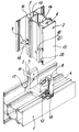
- the reference numeral 1 denotes a frame profile and the reference numeral 2 a rung profile of a T-connection.
- T-connectors 3 and 4 are fixed, which engage in correspondingly dimensioned hollow chambers 5 and 6 of the rung profile 2.
- the T-connectors 3 and 4 are provided in their upper end regions with receiving channels 7 and 8 into which fastening bolts 9 and 10 penetrating the rung profile 2 engage. These fastening bolts 9 and 10 produce a mechanical connection between the T-connectors 3 and 4 and the rung profile 2.
- fastening screws or other connecting means can optionally be used here.
- the T-connectors 3 and 4 are equipped with adhesive distribution channels 11 and 12 which run continuously in the longitudinal direction of the frame profile 1 and which have at least one transverse opening 17 and 18 which runs towards a hollow chamber wall 13, 14, 15 or 16 running parallel to the frame profile 1.
- a two-component adhesive is injected into the adhesive distribution channel 11 or 12, which is then distributed through the corresponding transverse opening 17 or 18 to the respective hollow chamber wall 13, 14, 15 or 16.
- the corresponding transverse openings 17 or 18 are preferably arranged in the immediate joint or joint area, so that a clean bond between the T-connectors 3 and 4 and the rung profile 2 is achieved in particular in the critical lower connection area.
- the transverse openings 17 or 18 can have the form of slots or bores and can be arranged either on one side or on both sides of the respective T-connector 3 or 4.
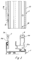
- FIG. 3 shows an exemplary embodiment of the invention in which the T-connectors 3a and 4a are provided with grooves 11a and 12a which are open on one side. These grooves 11a and 12a, which are open on one side, are closed after the rung profile 2 has been pushed on through the hollow chamber walls 13 and 16, respectively, to form an adhesive distribution channel.
- filler openings 18 and 19 are again provided in the rung profile 2, which are in alignment with the grooves 11a and 12a after assembly.
- a corresponding adhesive can again be poured into the lower connection area between the rung profile 2 and the T-connectors 3a and 4a, and a targeted, material-saving and clean gluing can be brought about.
- the T-connectors 3a and 4a according to FIG. 3 can also be provided with transverse openings in order to be able to distribute the adhesive on both sides of the respective T-connector 3a or 4a.
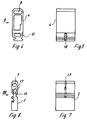
- the T-connector 3 and 4 are shown again according to the embodiment of Figures 1 and 2. It is clear that the transverse openings 17 or 18 can be slit-shaped or in the form of bores, in particular when bores are used, these can also be arranged diagonally to the cross section of the T-connector 3, optionally also offset in height from one another, depending on which distribution path is desired for the adhesive filled into the adhesive distribution channels 11 or 12.
- the construction according to the present invention has the advantage that the introduction of adhesive into the connection area can be carried out simply and in a targeted manner and the disadvantages of open adhesive processing are eliminated.
Landscapes
- Engineering & Computer Science (AREA)
- General Engineering & Computer Science (AREA)
- Civil Engineering (AREA)
- Structural Engineering (AREA)
- Mechanical Engineering (AREA)
- Joining Of Building Structures In Genera (AREA)
- Standing Axle, Rod, Or Tube Structures Coupled By Welding, Adhesion, Or Deposition (AREA)
- Body Structure For Vehicles (AREA)
- Mutual Connection Of Rods And Tubes (AREA)
- Channel Selection Circuits, Automatic Tuning Circuits (AREA)
- Use Of Switch Circuits For Exchanges And Methods Of Control Of Multiplex Exchanges (AREA)
- Digital Transmission Methods That Use Modulated Carrier Waves (AREA)
- Non-Disconnectible Joints And Screw-Threaded Joints (AREA)
- Mechanical Coupling Of Light Guides (AREA)
- Ladders (AREA)
- Door And Window Frames Mounted To Openings (AREA)
- Joining Of Corner Units Of Frames Or Wings (AREA)
- Bridges Or Land Bridges (AREA)
- Furniture Connections (AREA)
- Electric Connection Of Electric Components To Printed Circuits (AREA)
Abstract
Description
- Die vorliegende Erfindung betrifft eine T-Verbindung zwischen zwei Profilen, vorzugsweise einem Sprossen- und einem Rahmenprofil, wobei am Rahmenprofil mindestens ein in eine Hohlkammer des Sprossenprofiles hineinragender T-Verbinder befestigt ist, der mittels Schrauben, Bolzen od. dgl. mit dem Sprossenprofil mechanisch verbunden und zumindest im Stoß- oder Fugenbereich zwischen Rahmenprofil und Sprossenprofil zusätzlich mit dem Sprossenprofil verklebt ist.
- T-Verbindungen der vorerwähnten Art sind an sich bekannt.
- Bislang hat man die Verklebung zwischen T-Verbinder und Sprossenprofil in der Weise verwirklicht, daß man in den unteren Hohlkammerbereich, in den der T-Verbinder eingreift, vor dem Zusammensetzen von Rahmenprofil und Sprossenprofil einen Kleber eingestrichen hat, wobei hier Zweikomponenten-Kleber verwendet werden. Dieses weitestgehend offene Arbeiten mit angemischten Zweikomponenten-Klebern ist ganz allgemein mit den Nachteilen der unsauberen und luftbeeinflussenden Arbeitsbedingungen behaftet. Nachteilig ist weiterhin, daß in der Regel der in den unteren Endbereich der Hohlkammer eingespachtelte Kleber durch den T-Verbinder unkontrolliert weiter in die Hohlkammer hineingeschoben und verdrängt wird, so daß im eigentlichen Stoß- oder Fugenbereich zwischen Rahmenprofil und Sprossenprofil kein oder nur eine ungenügende Menge vom Kleber verbleibt.
- Um die vorstehend beschriebenen Nachteile zu beheben, liegt der vorliegenden Erfindung die Aufgabe zugrunde, eine T-Verbindung der gattungsgemäßen Art so zu gestalten, daß ein einfacheres und zielgerichtetes Einbringen des Klebers bei vereinfachten Arbeitsbedingungen erreicht wird.
- Diese Aufgabe wird erfindungsgemäß dadurch gelöst, daß der T-Verbinder mindestens einen parallel zum Rahmenprofil verlaufenden und über mindestens eine Einfüllöffnung im Sprossenprofil zugänglichen Kleberverteilungskanal aufweist, der zumindest eine zu einer parallel zum Rahmenprofil verlaufenden Hohlkammerwandung des Sprossenprofiles hin verlaufende Queröffnung aufweist.
- Diese Maßnahmen ermöglicht es, nach der rein mechanischen Verbindung zwischen T-Verbinder und Sprossenprofil von außen Kleber in den Kleberverteilungskanal und über dessen Queröffnungen in den Bereich zwischen Hohlkammerwandung einerseits und T-Verbinder andererseits zu pressen, wobei durch die Lage der Queröffnung oder der Queröffnungen konstruktiv sichergestellt werden kann, daß insbesondere im Stoß- oder Fugenbereich eine sichere Verklebung bewirkt wird.
- Weitere Merkmale der Erfindung sind Gegenstand von Unteransprüchen.
- In den beigefügten Zeichnungen sind Ausführungsbeispiele der
- Erfindung dargestellt, die im folgenden näher beschrieben werden.
- Es zeigen:
- Figur 1
- eine perspektivische Darstellung einer T-Verbindung zwischen einem Sprossen- und einem Rahmenprofil vor der endgültigen Montage,
- Figur 2
- eine weitere perspektivische Darstellung der T-Verbindung gemäß Figur 1 aus einer anderen Blickrichtung,
- Figur 3
- einen Teilschnitt durch ein Rahmenprofil einer T-Verbindung mit einer Teilansicht eines anzuschließendes Sprossenprofiles,
- Figur 4
- eine Stirnansicht eines T-Verbinders gemäß Ausführungsbeispiel nach Figur 1,
- Figur 5
- eine Ansicht in Richtung des Pfeiles V in Figur 4,
- Figur 6
- eine Stirnansicht eines weiteren T-Verbinders gemäß Ausführungsbeispiel nach Figur 1,
- Figur 7
- eine Ansicht in Richtung des Pfeiles VII in Figur 6.
- In den Figuren 1 und 2 ist mit dem Bezugszeichen 1 ein Rahmenprofil und mit dem Bezugszeichen 2 ein Sprossenprofil einer T-Verbindung bezeichnet.
- Am Rahmenprofil 1, welches im dargestellten Ausführungsbeispiel als wärmegedämmtes Profil ausgebildet ist, sind zwei T-Verbinder 3 und 4 festgelegt, welche in entsprechend dimensionierte Hohlkammern 5 bzw. 6 des Sprossenprofiles 2 eingreifen.
- Die T-Verbinder 3 und 4 sind in ihren oberen Endbereichen mit Aufnahmekanälen 7 bzw. 8 versehen in welche das Sprossenprofil 2 durchtretende Befestigungsbolzen 9 bzw. 10 eingreifen. Durch diese Befestigungsbolzen 9 bzw. 10 wird eine mechanische Verbindung zwischen den T-Verbindern 3 und 4 sowie dem Sprossenprofil 2 hergestellt. Statt der dargestellten Befestigungsbolzen können hier wahlweise auch Befestigungsschrauben oder andere Verbindungsmittel verwendet werden.
- Die T-Verbinder 3 und 4 sind mit in Längsrichtung des Rahmenprofiles 1 durchgehend verlaufenden Kleberverteilungskanälen 11 bzw. 12 ausgestattet, die zumindest eine zu einer parallel zum Rahmenprofil 1 verlaufenden Hohlkammerwandung 13, 14, 15 oder 16 hin verlaufende Queröffnung 17 bzw. 18 aufweisen.
- Die beiden Kleberverteilungskanäle 11, 12, die gemäß den Figuren 1 und 2 als stirnseitig offene Hohlkammern der jeweiligen T-Verbinder 3 bzw. 4 ausgebildet sind, sind nach dem Einschieben in die jeweilige Hohlkammer 5 bzw. 6 des Sprossenprofiles durch die dortigen stirnseitigen Wandungen geschlossen.
- Durch mindestens eine Einfüllöffnung 19 bzw. 20, die jeweils in einen Kleberverteilungskanal 11 bzw. 12 einmünden, kann nach dem Zusammensetzen der beiden Profile 1 und 2 beispielsweise ein Zweikomponenten-Kleber in den Kleberverteilungskanal 11 bzw. 12 eingespritzt werden, der sich dann durch die entsprechende Queröffnung 17 oder 18 an die jeweilige Hohlkammerwandung 13, 14, 15 oder 16 verteilt. Die entsprechenden Queröffnungen 17 oder 18 sind vorzugsweise im unmittelbaren Fugen- oder Stoßbereich angeordnet, so daß insbesondere im kritischen unteren Verbindungsbereich eine saubere Verklebung zwischen den T-Verbindern 3 und 4 sowie dem Sprossenprofil 2 erzielt wird.
- Die Queröffnungen 17 oder 18 können die Form von Schlitzen oder Bohrungen aufweisen und wahlweise einseitig oder beidseitig des jeweiligen T-Verbinders 3 oder 4 angeordnet sein.
- In Figur 3 ist ein Ausführungsbeispiel der Erfindung dargestellt, bei dem die T-Verbinder 3a bzw. 4a mit einseitig offenen Nuten 11a bzw. 12a versehen sind. Diese einseitig offenen Nuten 11a bzw. 12a werden nach dem Aufschieben des Sprossenprofiles 2 durch die Hohlkammerwandungen 13 bzw. 16 zu einem Kleberverteilungskanal geschlossen. Auch bei diesem Ausführungsbeispiel sind im Sprossenprofil 2 wiederum Einfüllöffnungen 18 und 19 vorgesehen, die nach der Montage in einer Flucht mit den Nuten 11a und 12a liegen. Hierdurch kann wieder ein entsprechender Kleber in den unteren Verbindungsbereich zwischen Sprossenprofil 2 und den T-Verbindern 3a und 4a eingefüllt und eine gezielte, materialsparende und saubere Verklebung herbeigeführt werden. Auch die T-Verbinder 3a und 4a nach Figur 3 können mit Queröffnungen versehen sein, um den Kleber auf beide Seiten des jeweiligen T-Verbinders 3a oder 4a verteilen zu können.
- In den Figuren 4 bis 7 sind noch einmal die T-Verbinder 3 und 4 gemäß Ausführungsbeispiel nach den Figuren 1 und 2 gezeigt. Es wird deutlich, daß die Queröffnungen 17 oder 18 schlitzförmig oder in Form von Bohrungen ausgebildet sein können, wobei insbesondere bei der Verwendung von Bohrungen diese auch diagonal zum Querschnitt des T-Verbinders 3, gegebenenfalls auch höhenversetzt zueinander, angeordnet sein können, je nachdem, welcher Verteilungsweg für den in die Kleberverteilungskanäle 11 bzw. 12 eingefüllte Klebstoff gewünscht wird.
- In jedem Falle bringt die Konstruktion gemäß der vorliegenden Erfindung den Vorteil mit sich, daß das Einbringen von Klebstoff in den Verbindungsbereich einfach und gezielt durchführbar ist und die Nachteile einer offenen Klebstoffverarbeitung behoben sind.
Claims (7)
- T-Verbindung zwischen zwei Profilen, vorzugsweise einem Sprossen- und einem Rahmenprofil, wobei am Rahmenprofil mindestens ein in eine Hohlkammer des Sprossenprofiles hineinragender T-Verbinder befestigt ist, der mittels Schrauben, Bolzen od. dgl. mit dem Sprossenprofil mechanisch verbunden und zumindest im Stoß- oder Fugenbereich zwischen Rahmenprofil und Sprossenprofil zusätzlich mit dem Sprossenprofil verklebt ist, dadurch gekennzeichnet, daß der T-Verbinder (3, 3a, 4, 4a) mindestens einen parallel zum Rahmenprofil (1) verlaufenden und über mindestens eine Einfüllöffnung (19, 20) im Sprossenprofil (2) zugänglichen Kleberverteilungskanal (11, 11a, 12, 12a) aufweist, der zumindest zu einer parallel zum Rahmenprofil (1) verlaufenden Hohlkammerwandung (13, 14, 15, 16) des Sprossenprofiles (2) hin verlaufende Queröffnung (17, 18) aufweist.
- T-Verbindung nach Anspruch 1, dadurch gekennzeichnet, daß der Kleberverteilungskanal (11, 11a, 12, 12a) in Längsrichtung durchlaufend offen und ausschließlich von den entsprechenden Hohlkammerwandungen begrenzt ist.
- T-Verbindung nach Anspruch 1 oder 2, dadurch gekennzeichnet, daß der Kleberverteilungskanal (11, 12) als stirnseitig offene Hohlkammer des T-Verbinders (3, 4) ausgebildet ist.
- T-Verbindung nach Anspruch 1 oder 2, dadurch gekennzeichnet, daß der Kleberverteilungskanal gebildet ist durch eine parallel zum Rahmenprofil (1) durchlaufende, einseitig offene Nut (11a, 12a) des T-Verbinders (3a, 4a) und die der offenen Nutseite gegenüberliegende Hohlkammerwandung (13, 14, 15, 16) des Sprossenprofiles (2).
- T-Verbindung nach einem oder mehreren der vorhergehenden Ansprüche, dadurch gekennzeichnet, daß die Queröffnungen (17) als Querbohrungen ausgeführt sind.
- T-Verbindung nach einem oder mehreren der Ansprüche 1 bis 4, dadurch gekennzeichnet, daß die Queröffnungen (18) in Form von Querschlitzen ausgeführt sind.
- T-Verbindung nach Anspruch 5, dadurch gekennzeichnet, daß die Querbohrungen (17) gegenüber der Längsachse des Sprossenprofiles (2) geneigt verlaufen.
Applications Claiming Priority (2)
| Application Number | Priority Date | Filing Date | Title |
|---|---|---|---|
| DE4306379 | 1993-03-02 | ||
| DE4306379A DE4306379A1 (de) | 1993-03-02 | 1993-03-02 | T-Verbindung zwischen zwei Profilen |
Publications (3)
| Publication Number | Publication Date |
|---|---|
| EP0614019A2 true EP0614019A2 (de) | 1994-09-07 |
| EP0614019A3 EP0614019A3 (en) | 1996-04-17 |
| EP0614019B1 EP0614019B1 (de) | 1997-11-19 |
Family
ID=6481677
Family Applications (1)
| Application Number | Title | Priority Date | Filing Date |
|---|---|---|---|
| EP94101169A Expired - Lifetime EP0614019B1 (de) | 1993-03-02 | 1994-01-27 | T Verbindung zwischen zwei Profilen |
Country Status (17)
| Country | Link |
|---|---|
| US (1) | US5494370A (de) |
| EP (1) | EP0614019B1 (de) |
| JP (1) | JP3609115B2 (de) |
| KR (1) | KR0166603B1 (de) |
| AT (1) | ATE160429T1 (de) |
| CA (1) | CA2116756C (de) |
| CZ (1) | CZ286628B6 (de) |
| DE (3) | DE4306379A1 (de) |
| DK (1) | DK0614019T3 (de) |
| ES (1) | ES2110131T3 (de) |
| FI (1) | FI105286B (de) |
| HU (1) | HU213142B (de) |
| IL (1) | IL108792A (de) |
| NO (1) | NO301299B1 (de) |
| PL (1) | PL173995B1 (de) |
| SI (1) | SI9400110B (de) |
| SK (1) | SK280065B6 (de) |
Cited By (4)
| Publication number | Priority date | Publication date | Assignee | Title |
|---|---|---|---|---|
| EP1580343A3 (de) * | 2004-03-23 | 2006-10-04 | Hermann Gutmann Werke AG | Stossverbinder zur Verbindung von Profilen |
| DE102007002605A1 (de) * | 2007-01-12 | 2008-07-17 | Eduard Hueck Gmbh & Co Kg | Stoßverbinder sowie Profilanordnung mit einem Stoßverbinder |
| CN109404393A (zh) * | 2018-11-08 | 2019-03-01 | 山东意象铝品科技有限公司 | 传动锁紧中梃连接件及其连接方法 |
| CN109555765A (zh) * | 2017-09-27 | 2019-04-02 | 盖慈有限公司 | 角接和/或对接装置 |
Families Citing this family (33)
| Publication number | Priority date | Publication date | Assignee | Title |
|---|---|---|---|---|
| DE59504612D1 (de) * | 1994-07-25 | 1999-02-04 | Alusuisse Lonza Services Ag | Verbindungselement |
| DE19604665A1 (de) * | 1996-02-09 | 1997-08-14 | Robert Soenser | Querverbinder für Profilstäbe |
| US5768845A (en) * | 1996-10-04 | 1998-06-23 | Skyline Displays, Inc. | Module panel and assembly |
| IT1297329B1 (it) * | 1997-11-26 | 1999-09-01 | Teseo Srl | Sistema di elementi per la formazione di tubazioni modulari in profilo estruso |
| CN1160516C (zh) * | 1998-05-13 | 2004-08-04 | 松下电器产业株式会社 | 电动送风机及采用它的电动吸尘器 |
| DE19828382C2 (de) | 1998-06-25 | 2003-03-27 | Reichel Phi Gmbh | Anordnung zum Befestigen eines einen Hohlquerschnitt aufweisenden Pfostens am Blendrahmen eines Fensters oder einer Türe aus Kunststoff oder Leichtmetall |
| DE19940574C1 (de) * | 1999-08-26 | 2001-05-17 | Reichel Phi Gmbh | Anordnung zur Bildung einer Kreuzverbindung zwischen einem Längspfosten und einem Querpfosten bei einem Fenster oder einer Türe aus Kunststoff oder Leichtmetall |
| BE1013251A3 (nl) * | 2000-01-26 | 2001-11-06 | Bekaert Sa Nv | Werkwijze voor het met elkaar verbinden van twee kunststofprofielen. |
| DE10015524A1 (de) * | 2000-03-30 | 2001-10-04 | Wicona Bausysteme Gmbh | T-Verbindung zwischen einem Sprossen- und einem Rahmenprofil |
| DE10115330C1 (de) * | 2001-03-28 | 2003-06-12 | Wicona Bausysteme Gmbh | Verbinder zur Schaffung von Eck- oder Stoßverbindungen |
| US6708858B2 (en) * | 2002-06-06 | 2004-03-23 | Blanking Systems, Inc. | Clamp pieces for lower frame assembly of blanking tool |
| KR100471961B1 (ko) * | 2002-08-07 | 2005-03-10 | 광건티앤씨(주) | 조립식 문짝 |
| DE10345624A1 (de) * | 2003-09-29 | 2005-05-04 | Kosak Adrian | T-Verbinderelement |
| US7557675B2 (en) * | 2005-03-22 | 2009-07-07 | Radiacion Y Microondas, S.A. | Broad band mechanical phase shifter |
| US7597771B2 (en) * | 2006-02-07 | 2009-10-06 | Comfort Line Ltd. | Pultrusion method and related article |
| DE102008039207A1 (de) * | 2008-08-22 | 2010-03-04 | Rehau Ag + Co. | Rahmenprofil-Baugruppe für einen Fenster- oder Türrahmen sowie Verfahren zur Montage einer derartigen Baugruppe |
| EP2199523A1 (de) | 2008-12-22 | 2010-06-23 | Hermann Gutmann Werke AG | Verbinder |
| KR200461174Y1 (ko) * | 2009-10-27 | 2012-06-26 | 황민선 | 샷시조립체의 연결구조 |
| DE102012006899B4 (de) | 2012-04-05 | 2025-03-27 | Heroal - Johann Henkenjohann Gmbh & Co. Kg | Stoßverbindung vorzugsweise eines Fensterrahmens |
| DE202012007564U1 (de) | 2012-08-09 | 2012-09-24 | Nögel Montagetechnik Vertriebsgesellschaft mbH | Profilverbindungsanordnung |
| WO2014189630A1 (en) * | 2013-04-13 | 2014-11-27 | Milgard Manufacturing Incorporated | Fenestration trim assembly |
| TWI621771B (zh) * | 2013-10-18 | 2018-04-21 | Window structure with built-in folding yarn and frame material positioning member thereof and assembly method thereof | |
| US9127504B2 (en) * | 2013-10-30 | 2015-09-08 | C. R. Laurence Co., Inc. | Corner assembly for metal framed glass panel doors, windows and wall partitions |
| DE102015007804B3 (de) | 2015-06-22 | 2016-02-18 | Petra Sabine Kosak | Stoßverbinder für Kleberinjektion sowie Stoßverbinderkombination und Rahmen |
| CN105863469A (zh) * | 2016-06-06 | 2016-08-17 | 天津市万佳建筑装饰安装工程有限公司 | 门窗组装中梃角码两端的注胶导流片 |
| US9932734B1 (en) * | 2016-10-03 | 2018-04-03 | Roger Winter | Deck component with post sleeve and flanges |
| US10174498B2 (en) | 2016-10-03 | 2019-01-08 | Roger Winter | Deck component with post sleeve and flanges |
| CN110952881A (zh) * | 2019-11-25 | 2020-04-03 | 上海锐视门窗有限公司 | 一种全隐框上悬窗 |
| AU2021106516A4 (en) * | 2021-04-21 | 2021-11-04 | Rhino Rack Australia Pty Limited | Means of forming T-joint between extruded elements |
| BE1029716B1 (nl) * | 2021-08-27 | 2023-03-27 | Renson Sunprotection Screens | Een terrasoverkapping en werkwijze voor het vervaardigen daarvan |
| US12291919B1 (en) * | 2021-12-03 | 2025-05-06 | Andersen Corporation | Inject clip for fenestration frames and methods |
| US12209452B1 (en) * | 2023-07-07 | 2025-01-28 | Wincore Window Company, Llc | Apparatus and method for mulled window installation |
| DE102024112650A1 (de) * | 2024-05-06 | 2025-11-06 | Geze Gmbh | Profilanordnung |
Family Cites Families (10)
| Publication number | Priority date | Publication date | Assignee | Title |
|---|---|---|---|---|
| US2736930A (en) * | 1953-10-28 | 1956-03-06 | John D Longley | Door frame |
| DE2116125A1 (de) * | 1971-04-02 | 1972-10-19 | Pasche H | Vorrichtung zur Herstellung einer Eckverbindung an Kunststoffrahmen-Hohlprofilen |
| BE767043A (fr) * | 1971-05-12 | 1971-10-01 | Janssen Leopold M L | Cloison double paroi et elements de cloison. |
| US3828516A (en) * | 1971-11-24 | 1974-08-13 | Wieland Werke Ag | Press-fitted joint between a transom bar and a frame or sash bar for use on windows, doors or the like |
| DE2204646A1 (de) * | 1972-02-01 | 1973-08-16 | Schuermann & Co Heinz | Verbindungsvorrichtung, insbesondere fuer metallbauelemente, wie profile, rohre od. dgl |
| DE2750307C2 (de) * | 1977-11-10 | 1986-08-21 | SCHÜCO Heinz Schürmann GmbH & Co, 4800 Bielefeld | Eck- oder T-Verbindung zweier Profile |
| DE3041326C2 (de) * | 1980-11-03 | 1984-04-26 | Wieland-Werke Ag, 7900 Ulm | Stoßverbindung eines Kämpferprofils mit einem Rahmen- oder Sprossenprofil für Fenster, Türen o.dgl. |
| DE8415881U1 (de) * | 1984-05-24 | 1984-09-27 | SCHÜCO Heinz Schürmann GmbH & Co, 4800 Bielefeld | Sprossenfenster oder sprossentuer aus kunststoff |
| GB2256908B (en) * | 1991-06-19 | 1994-06-08 | Scholes Ernest M H | Method of jointing extruded sections |
| DE4125976A1 (de) * | 1991-08-06 | 1993-02-11 | Philippi Gerd | Profilverbindung, insbesondere fuer aluminium-leichtbau |
-
1993
- 1993-03-02 DE DE4306379A patent/DE4306379A1/de not_active Withdrawn
- 1993-03-02 DE DE9321523U patent/DE9321523U1/de not_active Expired - Lifetime
-
1994
- 1994-01-27 EP EP94101169A patent/EP0614019B1/de not_active Expired - Lifetime
- 1994-01-27 AT AT94101169T patent/ATE160429T1/de active
- 1994-01-27 DK DK94101169T patent/DK0614019T3/da active
- 1994-01-27 ES ES94101169T patent/ES2110131T3/es not_active Expired - Lifetime
- 1994-01-27 DE DE59404593T patent/DE59404593D1/de not_active Expired - Lifetime
- 1994-02-24 HU HU9400544A patent/HU213142B/hu not_active IP Right Cessation
- 1994-02-28 CZ CZ1994449A patent/CZ286628B6/cs not_active IP Right Cessation
- 1994-02-28 JP JP02994994A patent/JP3609115B2/ja not_active Expired - Fee Related
- 1994-02-28 PL PL94302422A patent/PL173995B1/pl unknown
- 1994-03-01 FI FI940973A patent/FI105286B/fi active
- 1994-03-01 NO NO940706A patent/NO301299B1/no not_active IP Right Cessation
- 1994-03-01 CA CA002116756A patent/CA2116756C/en not_active Expired - Fee Related
- 1994-03-01 IL IL10879294A patent/IL108792A/en not_active IP Right Cessation
- 1994-03-02 KR KR1019940003956A patent/KR0166603B1/ko not_active Expired - Fee Related
- 1994-03-02 US US08/205,043 patent/US5494370A/en not_active Expired - Lifetime
- 1994-03-02 SK SK257-94A patent/SK280065B6/sk not_active IP Right Cessation
- 1994-03-02 SI SI9400110A patent/SI9400110B/sl not_active IP Right Cessation
Cited By (6)
| Publication number | Priority date | Publication date | Assignee | Title |
|---|---|---|---|---|
| EP1580343A3 (de) * | 2004-03-23 | 2006-10-04 | Hermann Gutmann Werke AG | Stossverbinder zur Verbindung von Profilen |
| DE102007002605A1 (de) * | 2007-01-12 | 2008-07-17 | Eduard Hueck Gmbh & Co Kg | Stoßverbinder sowie Profilanordnung mit einem Stoßverbinder |
| CN109555765A (zh) * | 2017-09-27 | 2019-04-02 | 盖慈有限公司 | 角接和/或对接装置 |
| EP3461984A1 (de) * | 2017-09-27 | 2019-04-03 | GEZE GmbH | Eck- und/oder stossverbindung |
| CN109555765B (zh) * | 2017-09-27 | 2021-02-09 | 盖慈有限公司 | 角接和/或对接装置 |
| CN109404393A (zh) * | 2018-11-08 | 2019-03-01 | 山东意象铝品科技有限公司 | 传动锁紧中梃连接件及其连接方法 |
Also Published As
| Publication number | Publication date |
|---|---|
| DK0614019T3 (da) | 1998-07-27 |
| FI940973A7 (fi) | 1994-09-03 |
| US5494370A (en) | 1996-02-27 |
| HU213142B (en) | 1997-02-28 |
| IL108792A (en) | 1996-09-12 |
| JPH06323060A (ja) | 1994-11-22 |
| ATE160429T1 (de) | 1997-12-15 |
| PL302422A1 (en) | 1994-09-05 |
| CA2116756A1 (en) | 1994-09-03 |
| CZ44994A3 (en) | 1995-01-18 |
| HU9400544D0 (en) | 1994-05-30 |
| FI940973A0 (fi) | 1994-03-01 |
| SK280065B6 (sk) | 1999-07-12 |
| NO301299B1 (no) | 1997-10-06 |
| PL173995B1 (pl) | 1998-05-29 |
| EP0614019B1 (de) | 1997-11-19 |
| EP0614019A3 (en) | 1996-04-17 |
| KR0166603B1 (ko) | 1999-05-01 |
| FI105286B (fi) | 2000-07-14 |
| KR940021978A (ko) | 1994-10-19 |
| DE9321523U1 (de) | 1998-12-17 |
| CZ286628B6 (cs) | 2000-05-17 |
| ES2110131T3 (es) | 1998-02-01 |
| NO940706L (no) | 1994-09-05 |
| DE59404593D1 (de) | 1998-01-02 |
| JP3609115B2 (ja) | 2005-01-12 |
| NO940706D0 (no) | 1994-03-01 |
| SI9400110A (en) | 1994-09-30 |
| DE4306379A1 (de) | 1994-09-08 |
| CA2116756C (en) | 2003-12-09 |
| SK25794A3 (en) | 1994-09-07 |
| SI9400110B (en) | 2001-12-31 |
| HUT72258A (en) | 1996-04-29 |
Similar Documents
| Publication | Publication Date | Title |
|---|---|---|
| EP0614019B1 (de) | T Verbindung zwischen zwei Profilen | |
| DE4210456C2 (de) | Querverbindung für Profilstäbe mittels Zuggliedern | |
| DE3426994A1 (de) | Duebel | |
| DE1906151A1 (de) | Bauspielsystem | |
| DE1609438A1 (de) | Verbindungseinrichtung fuer vorfabrizierte Bauelemente | |
| EP2512851B1 (de) | Stossverbindung zwischen enden von dichtungssträngen oder eines dichtungsstrangs | |
| DE3340291A1 (de) | Druckmittelzylinder | |
| DE29722127U1 (de) | Mechanischer Verbinder | |
| EP0371237B1 (de) | Bausatz für eine Türzarge | |
| DE4322724A1 (de) | Verfahren zur Erhöhung der Querbelastbarkeit von mechanischen Verbindungen | |
| DE4143352C2 (de) | Profilstab | |
| EP0267200A1 (de) | Beschlag zum lösbaren verbinden von zwei bauteilen. | |
| DE3145375C2 (de) | Mehrteiliges Rahmenprofil | |
| EP0304830B1 (de) | Rahmen aus miteinander verbundenen Tragprofilabschnitten aus Holz, Kunststoff oder einem Verbundwerkstoff | |
| DE9215844U1 (de) | Beschlagteileverbindung | |
| EP3460161B1 (de) | Verfahren und verbindungsanordnung zum verbinden eines pfostens mit einem rahmenprofil bei einem fenster oder einer türe aus kunststoff | |
| DE102018108402B4 (de) | Verbindungssteckteil für einen Felgenring, insbesondere für Fahrräder | |
| DE20115618U1 (de) | Parallelverbinder | |
| EP0835978A2 (de) | Rahmen für Fenster, Türen, Fassaden oder dergl. | |
| EP3406916B1 (de) | Winkelverbinder für tragprofile | |
| EP0167106A2 (de) | Hohldübel für den Eisenbahnbau | |
| DE3315097C1 (de) | Verbindungselement zum lösbaren Verbinden von Werkzeug- oder Vorrichtungskörpern | |
| DE2614082B2 (de) | Fenster mit einem Flügelrahmen aus vier winkelförmigen, um die Scheibe herum zusammengesetzten Rahmenteilen | |
| DE9014027U1 (de) | Energieführungskette | |
| DE2648315A1 (de) | Abdeckgehaeuse fuer gestaenge an fenstern oder tueren |
Legal Events
| Date | Code | Title | Description |
|---|---|---|---|
| PUAI | Public reference made under article 153(3) epc to a published international application that has entered the european phase |
Free format text: ORIGINAL CODE: 0009012 |
|
| AK | Designated contracting states |
Kind code of ref document: A2 Designated state(s): AT BE CH DE DK ES FR GB IE IT LI LU NL PT SE |
|
| PUAL | Search report despatched |
Free format text: ORIGINAL CODE: 0009013 |
|
| AK | Designated contracting states |
Kind code of ref document: A3 Designated state(s): AT BE CH DE DK ES FR GB IE IT LI LU NL PT SE |
|
| 17P | Request for examination filed |
Effective date: 19960321 |
|
| GRAG | Despatch of communication of intention to grant |
Free format text: ORIGINAL CODE: EPIDOS AGRA |
|
| 17Q | First examination report despatched |
Effective date: 19970113 |
|
| GRAH | Despatch of communication of intention to grant a patent |
Free format text: ORIGINAL CODE: EPIDOS IGRA |
|
| GRAH | Despatch of communication of intention to grant a patent |
Free format text: ORIGINAL CODE: EPIDOS IGRA |
|
| ITF | It: translation for a ep patent filed | ||
| GRAA | (expected) grant |
Free format text: ORIGINAL CODE: 0009210 |
|
| AK | Designated contracting states |
Kind code of ref document: B1 Designated state(s): AT BE CH DE DK ES FR GB IE IT LI LU NL PT SE |
|
| REF | Corresponds to: |
Ref document number: 160429 Country of ref document: AT Date of ref document: 19971215 Kind code of ref document: T |
|
| REG | Reference to a national code |
Ref country code: CH Ref legal event code: NV Representative=s name: ISLER & PEDRAZZINI AG Ref country code: CH Ref legal event code: EP |
|
| GBT | Gb: translation of ep patent filed (gb section 77(6)(a)/1977) |
Effective date: 19971119 |
|
| REF | Corresponds to: |
Ref document number: 59404593 Country of ref document: DE Date of ref document: 19980102 |
|
| REG | Reference to a national code |
Ref country code: ES Ref legal event code: FG2A Ref document number: 2110131 Country of ref document: ES Kind code of ref document: T3 |
|
| ET | Fr: translation filed | ||
| REG | Reference to a national code |
Ref country code: PT Ref legal event code: SC4A Free format text: AVAILABILITY OF NATIONAL TRANSLATION Effective date: 19971210 |
|
| REG | Reference to a national code |
Ref country code: DK Ref legal event code: T3 |
|
| PLBE | No opposition filed within time limit |
Free format text: ORIGINAL CODE: 0009261 |
|
| STAA | Information on the status of an ep patent application or granted ep patent |
Free format text: STATUS: NO OPPOSITION FILED WITHIN TIME LIMIT |
|
| 26N | No opposition filed | ||
| REG | Reference to a national code |
Ref country code: GB Ref legal event code: IF02 |
|
| REG | Reference to a national code |
Ref country code: CH Ref legal event code: PCAR Free format text: ISLER & PEDRAZZINI AG;POSTFACH 1772;8027 ZUERICH (CH) |
|
| PGFP | Annual fee paid to national office [announced via postgrant information from national office to epo] |
Ref country code: LU Payment date: 20090123 Year of fee payment: 16 Ref country code: IE Payment date: 20090122 Year of fee payment: 16 |
|
| REG | Reference to a national code |
Ref country code: IE Ref legal event code: MM4A |
|
| PG25 | Lapsed in a contracting state [announced via postgrant information from national office to epo] |
Ref country code: IE Free format text: LAPSE BECAUSE OF NON-PAYMENT OF DUE FEES Effective date: 20100127 |
|
| PGFP | Annual fee paid to national office [announced via postgrant information from national office to epo] |
Ref country code: DK Payment date: 20110125 Year of fee payment: 18 |
|
| PGFP | Annual fee paid to national office [announced via postgrant information from national office to epo] |
Ref country code: AT Payment date: 20110120 Year of fee payment: 18 Ref country code: CH Payment date: 20110125 Year of fee payment: 18 Ref country code: SE Payment date: 20110121 Year of fee payment: 18 Ref country code: PT Payment date: 20110124 Year of fee payment: 18 Ref country code: FR Payment date: 20110201 Year of fee payment: 18 |
|
| PGFP | Annual fee paid to national office [announced via postgrant information from national office to epo] |
Ref country code: BE Payment date: 20110124 Year of fee payment: 18 |
|
| PGFP | Annual fee paid to national office [announced via postgrant information from national office to epo] |
Ref country code: ES Payment date: 20110121 Year of fee payment: 18 Ref country code: GB Payment date: 20110121 Year of fee payment: 18 |
|
| PGFP | Annual fee paid to national office [announced via postgrant information from national office to epo] |
Ref country code: IT Payment date: 20120128 Year of fee payment: 19 |
|
| BERE | Be: lapsed |
Owner name: *SCHUCO INTERNATIONAL K.G. Effective date: 20120131 |
|
| REG | Reference to a national code |
Ref country code: PT Ref legal event code: MM4A Free format text: LAPSE DUE TO NON-PAYMENT OF FEES Effective date: 20120727 |
|
| REG | Reference to a national code |
Ref country code: CH Ref legal event code: PL |
|
| REG | Reference to a national code |
Ref country code: SE Ref legal event code: EUG |
|
| REG | Reference to a national code |
Ref country code: DK Ref legal event code: EBP |
|
| GBPC | Gb: european patent ceased through non-payment of renewal fee |
Effective date: 20120127 |
|
| PG25 | Lapsed in a contracting state [announced via postgrant information from national office to epo] |
Ref country code: LU Free format text: LAPSE BECAUSE OF NON-PAYMENT OF DUE FEES Effective date: 20100127 |
|
| REG | Reference to a national code |
Ref country code: FR Ref legal event code: ST Effective date: 20120928 |
|
| PG25 | Lapsed in a contracting state [announced via postgrant information from national office to epo] |
Ref country code: SE Free format text: LAPSE BECAUSE OF NON-PAYMENT OF DUE FEES Effective date: 20120128 Ref country code: GB Free format text: LAPSE BECAUSE OF NON-PAYMENT OF DUE FEES Effective date: 20120127 Ref country code: CH Free format text: LAPSE BECAUSE OF NON-PAYMENT OF DUE FEES Effective date: 20120131 Ref country code: LI Free format text: LAPSE BECAUSE OF NON-PAYMENT OF DUE FEES Effective date: 20120131 |
|
| PG25 | Lapsed in a contracting state [announced via postgrant information from national office to epo] |
Ref country code: PT Free format text: LAPSE BECAUSE OF NON-PAYMENT OF DUE FEES Effective date: 20120727 |
|
| REG | Reference to a national code |
Ref country code: AT Ref legal event code: MM01 Ref document number: 160429 Country of ref document: AT Kind code of ref document: T Effective date: 20120127 |
|
| PG25 | Lapsed in a contracting state [announced via postgrant information from national office to epo] |
Ref country code: BE Free format text: LAPSE BECAUSE OF NON-PAYMENT OF DUE FEES Effective date: 20120131 Ref country code: FR Free format text: LAPSE BECAUSE OF NON-PAYMENT OF DUE FEES Effective date: 20120131 |
|
| PG25 | Lapsed in a contracting state [announced via postgrant information from national office to epo] |
Ref country code: AT Free format text: LAPSE BECAUSE OF NON-PAYMENT OF DUE FEES Effective date: 20120127 Ref country code: DK Free format text: LAPSE BECAUSE OF NON-PAYMENT OF DUE FEES Effective date: 20120131 |
|
| PGFP | Annual fee paid to national office [announced via postgrant information from national office to epo] |
Ref country code: DE Payment date: 20130208 Year of fee payment: 20 |
|
| PGFP | Annual fee paid to national office [announced via postgrant information from national office to epo] |
Ref country code: NL Payment date: 20130121 Year of fee payment: 20 |
|
| REG | Reference to a national code |
Ref country code: ES Ref legal event code: FD2A Effective date: 20130705 |
|
| PG25 | Lapsed in a contracting state [announced via postgrant information from national office to epo] |
Ref country code: ES Free format text: LAPSE BECAUSE OF NON-PAYMENT OF DUE FEES Effective date: 20120128 |
|
| REG | Reference to a national code |
Ref country code: DE Ref legal event code: R071 Ref document number: 59404593 Country of ref document: DE |
|
| REG | Reference to a national code |
Ref country code: NL Ref legal event code: V4 Effective date: 20140127 |
|
| PG25 | Lapsed in a contracting state [announced via postgrant information from national office to epo] |
Ref country code: DE Free format text: LAPSE BECAUSE OF EXPIRATION OF PROTECTION Effective date: 20140128 |